


™ |
Pub. 988-0154-651 |
LGC-3000, LGC-Baja
GPS Modules
Installation Instructions
This instruction sheet tells how to install your LGC-3000 or LGC-Baja GPS module and connect it to a NMEA 2000® network using LowranceNET™ network components.
The LGC-Baja is a ruggedized module designed to withstand the rigors of offroad automobile racing. It works just like the LGC-3000, and for simplicity we will only refer to the LGC-3000 in the rest of this instruction sheet.
The LGC-3000 GPS module, like the other Lowrance Electronic Probe (EP) sensors, is designed only for use with a NMEA 2000 Network. It MUST be connected to a NMEA 2000 network or it WILL NOT function.
CAUTION:
Installing LowranceNET NMEA 2000 devices is significantly different from installing earlier Lowrance components without NMEA 2000 features. You should read all of the installation instructions before proceeding. You should decide where to install all components before drilling any holes in your vessel or vehicle.
Some sonar or GPS display units may require: 1. a software upgrade to display NMEA 2000 data correctly; and 2. a manual addendum describing how to operate the sensor. You can download these free and get additional information on the NMEA 2000® compatible LowranceNET™ system at our web site, www.lowrance.com.
All Lowrance NMEA 2000 capable devices are either NMEA 2000 certified or certification is pending. See our web site for the latest product status information.
LGC-3000 Module, bottom view (left) and top view (right).
1
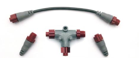
The LGC-3000 consists of a red male threaded cable connector and the GPS module. The GPS module contains a 12-parallel channel GPS+WAAS receiver. The cable length from the connector to the GPS module is 18 inches (45.7 cm).
The module packs with: a 15 foot (4.6 m) extension cable with a male connector on one end and a female connector on the other end; one red network T connector; as well as the parts needed for mounting the module on a flat surface or the optional pole mount.
Some packages may include the QM-1 quick mount bracket, which is also available as an option. (The QM-1 includes its own instruction sheet, part 988-0154-502.) The QM-1 is a quick-connecting, bayonet-style mounting device. It is designed so you can easily mount and dismount any antenna module similar to the LGC-3000, LGC-Baja, LGC-2000, LGC-12W or EGC-12W.
An optional marine pole mount and optional magnet for temporary mounting on any ferrous metal surface are also available. For ordering information, see the end of this instruction sheet.
Tools and Supplies
Other supplies are not included, unless otherwise indicated. Recommended tools are pliers and a flathead screwdriver. If you need to route the module connector through a bulkhead, you will need a drill and a 7/8" (22 mm) drill bit. If you are mounting the module directly to a console or similar surface, you will need a 3/16" (4.75 mm) drill bit for the screw holes.
If you wish to add additional NMEA 2000 sensors or more than one display unit, you may need a one-time purchase of a LowranceNET Node Kit.
LowranceNET Node Kit for a NMEA 2000 network. Includes a 2 foot (61 cm) extension cable, T connector, 120-ohm male terminator and 120ohm female terminator.
2
For complete instructions on setting up a new NMEA 2000 network or expanding an existing one, see the other document packed with your LGC-3000 GPS module, "Setup and Installation of NMEA 2000 Networks, General Information," part number 988-0154-173. If that document is missing, it can be downloaded free from the Lowrance web site.
Mounting
The GPS module can be mounted on any flat surface, provided there is access behind the mounting surface for the screws. The optional magnet allows the module to be easily used on cars or off-road vehicles. The optional pole mount adapter lets you mount the antenna on a pole or swivel mount that uses standard marine 1"-14 threads.
Surface Mount
The GPS module can be easily installed on any flat surface that is at least 3-1/2" (90 mm) wide. Be sure that a clear, unobstructed view of the sky is available at the selected location. GPS signals travel "line-of- sight" at very high frequencies, so nearly anything blocking the antenna can stop the unit from finding a satellite.
Caution:
Do not mount the GPS module in the direct path of a radar antenna's beam. Radar radiates high-energy signals that can interfere with GPS signal reception.
In an automobile, you may achieve good reception by simply placing the external antenna on the top of the dash, at the base of the windshield. A piece of the rubber non-skid shelf liner material available in recreational vehicle supply stores will help hold the antenna in place. This may not work well if you have a cab-over design pickup truck camper or motor home. If dashboard reception is poor, simply relocate the antenna module elsewhere on the vehicle for a clearer view of the sky.
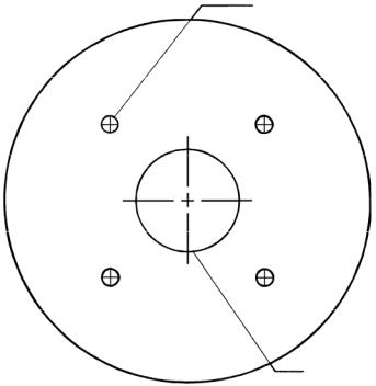
Once you’ve determined the mounting location, use the template on the following page to drill the screw holes. The screws supplied with this unit are about 1-1/8" long (4 mm x 30 mm). Drill 3/16" (4.75 mm) holes for the mounting screws.
If you need to route the cable through the mounting surface, drill a 7/8" (22 mm) hole for the cable's connector. The notch in the antenna housing allows the cable to pass through, if desired, instead of routing it down through the mounting surface.
After drilling the holes, pass the O-ring over the cable and press it into the groove on the bottom of the antenna housing. (If you are using the housing notch to route the cable outside, you may need to cut a notch in
3
the O-ring for a proper fit.) Now attach the antenna to the mounting surface, using the supplied 4 mm screws and the lock washers. Route the cable to where it connects to the network and plug it in. The GPS module installation is finished.
Drill size 3/16" (4.75 mm)
Drill four places.
Drill size 7/8"
(22 mm ) if needed.
GPS module mounting template.
4

Magnet Mount
The optional magnet lets you temporarily mount the GPS module on any ferrous metal surface, such as a car roof.
Under side view showing where to place the magnet.
To use the magnet, simply peel the backing off the magnet's adhesive coating and press the magnet to the bottom of the antenna housing. The module is ready for use.
Pole Mount
The GPS module attaches to the optional pole mount adapter with the supplied 4 mm screws. You can route the cable through the notch in the module housing and down the side of the pole. Or, you can pass it down through the pole mount adapter and run the cable inside the pole. The 1"- 14 threads on the pole mount adapter fit a standard marine antenna mounting pole.
Pole Mount.
Power Connections
The display unit that you will use with the GPS module came with a power/data cable that splits into three branches, each with several ex-
5
 Loading...