


Pub. 988-0154-451
EP-25 Speed
Electronic Sensor
Installation Instructions
This instruction sheet tells how to install your EP-25 Speed sensor and connect it to a NMEA 2000 network using LowranceNET network components. You must refer to your digital gauge, sonar or GPS unit's manual for sensor operation instructions.
Caution:
Installing LowranceNET NMEA 2000 devices is significantly different from installing earlier Lowrance components without NMEA 2000 features. You should read all of the installation instructions before proceeding. You should decide where to install all components before drilling any holes in your vessel.
Some sonar or GPS units may require a software upgrade to display NMEA 2000 data correctly and a manual addendum describing how to operate the sensor. You can download these free and get additional information on the NMEA 2000 compatible LowranceNET system at our web site, www.lowrance.com.
All Lowrance NMEA 2000 capable devices are either NMEA 2000 certified or certification is pending. See our web site for the latest product status information.
Smart module 
Paddle wheel module
The EP-25 Speed sensor.
The EP-25 consists of the paddle wheel module, a blue female locking cable connector and the smart module. The cable length from the
1
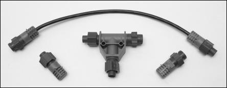
connector to the smart module is 18 inches (46 cm) and from the smart module to the paddle wheel module is 10 feet (3 meters).
The smart module converts speed data from the paddle wheel to the NMEA 2000 data format. This allows any digital gauge, sonar or GPS unit connected to the NMEA 2000 network to display the speed.
The EP-25 Speed, like the other Lowrance Electronic Probe (EP) sensors, is designed only for use with a NMEA 2000 Network. It must be connected to a NMEA 2000 network or it will not function.
Tools and Supplies
Your EP sensor packs with a T connector needed to attach it to a LowranceNET NMEA 2000 network. If you are connecting to an existing LowranceNET network, those are all the electronic components you need. If this is the first sensor you are connecting, you will also need a one-time purchase of a LowranceNET Node Kit.
LowranceNET Node Kit for a NMEA 2000 network. Includes a 2 foot (61 cm) extension cable, T connector, 120-ohm male terminator and 120ohm female terminator.
For complete instructions on setting up a new NMEA 2000 network or expanding an existing one refer to the "Setup and Installation of NEMA 2000 Networks, General Information" document (part number 988- 0154-172) included with your EP-25 sensor. If that document is missing it can be downloaded free from the Lowrance web site.
Supplies are not included, unless otherwise indicated. Required supplies for this job are: four #8 stainless steel wood screws (3/4" or 19 mm long), high quality, marine grade aboveor below-waterline sealant compound.
Recommended tools for this job include: screwdriver, drill, 1/8" (3 mm) drill bit for pilot holes. If you want to feed the smart module or blue cable connector through a transom or bulkhead, you will also need a 7/8" (22 mm) drill bit.
2
Installation
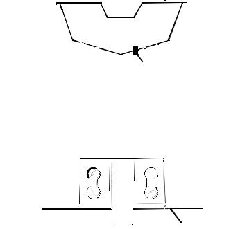
To install the speed sensor, first find a location on the boat's transom where the water flow is smoothest. Don't mount the paddle wheel module behind strakes or ribs. These will disturb the water flow to the paddle wheel.
Make sure the paddle wheel will remain in the water when the boat is on plane. Also make sure the location doesn't interfere with the boat's trailer. Typically, the paddle wheel module is mounted about one foot (30.5 cm) to the side of the transom's centerline.
good location
Stern view showing good mounting location on transom.
Once you've determined the proper location for the paddle wheel, place it on the transom. The bottom of the bracket should be flush with the hull's bottom. Using the paddle wheel's bracket as a template, mark the hull for the screws' pilot holes. Drill four 1/8" (3 mm) holes, one in each end of the slots.
Rear view
view
Bottom of
of hull
hull
Paddle wheel module rear view.
Mount the paddle wheel module to the hull using four #8 stainless steel wood screws. Use a high quality, marine grade aboveor belowwaterline sealant to seal the screws. Make sure the paddle wheel bracket is flush with the bottom of the hull and tighten the screws.
3
 Loading...