


`Pub. 988-0154-431
EP-10 Fuel Flow
Electronic Sensor
Installation Instructions
This instruction manual explains how to install your EP-10 fuel flow sensor and connect it to a NMEA 2000 network using LowranceNET network components. You must refer to your digital gauge, sonar or GPS unit's manual for sensor operation instructions.
Caution:
Installing LowranceNET NMEA 2000 devices is significantly different from installing earlier Lowrance components without NMEA 2000 features. You should read all of the installation instructions before proceeding. You should decide where to install all components before drilling any holes in your vessel.
Some sonar or GPS units may require a software upgrade to display NMEA 2000 data correctly and a manual addendum describing how to operate the sensor. You can download these free and get additional information on the NMEA 2000 compatible LowranceNET system at our web site, www.lowrance.com.
WARNING:
Do not use this sensor with diesel engine fuel systems. The EP-10 is designed only for gasoline engines. Please see fuel filter warning on page 4 for additional information.
Blue female NMEA 2000 connector
Sensor module
The EP-10 Fuel Flow sensor.
1
All Lowrance NMEA 2000 capable devices are NMEA 2000 certified or certification is pending. See our web site for the latest product status information.
The EP-10 consists of a blue female locking cable connector and the sensor module. The sensor module contains a turbine to measure fuel flow and electronics which convert flow data to the NMEA 2000 data format. The cable length from the connector to the smart module is 10 feet. The EP-10 sensor is designed to work with gasoline engines only.
This sensor has been optimized to measure flow rates between 0.6 to 45 gallons (U.S.) per hour, but it will operate at flow rates outside that range. The sensor will add 0.5 PSI of back pressure on the fuel system with a flow rate of 20 gallons per hour. At the rate of 40 gallons per hour the back pressure will be 1 PSI.
The EP-10, like other Lowrance Electronic Probe (EP) sensors, is designed only for use with a NMEA 2000 Network. It must be connected to a NMEA 2000 network or it will not function.
Tools and Supplies
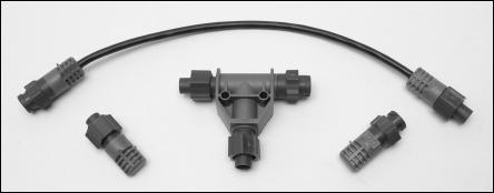
Your EP-10 sensor comes with a T connector. The T connector is needed to attach the sensor to a LowranceNET NMEA 2000 network. If you are connecting to an existing LowranceNET network, those are all the electronic components you need. If this is the first sensor you are connecting, you also will need a one-time purchase of a LowranceNET Node Kit.
LowranceNET Node Kit for a NMEA 2000 network. Includes a 2 foot extension cable, T connector, 120-ohm male terminator and 120-ohm female terminator.
For complete instructions on setting up a new NMEA 2000 network or expanding an existing one refer to the "Setup and Installation of NMEA 2000 Networks, General Information" document (part number 988-
2
0154-172) included with your EP-10 sensor. If that document is missing it can be downloaded free from the Lowrance web site.
Other supplies are not included unless otherwise indicated. Required supplies include cable ties or other fasteners to secure the hose and cable; an in-line fuel filter and any items needed to install the filter. Two 1" hose clamps are included with the sensor.
We assume you already have a fuel line installed. The EP-10 was designed to fit a typical 3/8" (9.5 mm) SAE USCG Type A1 fuel hose. If your engine has different diameter hoses or metal fuel lines a section of 3/8" fuel line must be installed between the sensor and the existing lines.
Recommended tools are a flathead screwdriver to tighten the clamps and a knife to cut the fuel hose. If you need to route the sensor connector through a bulkhead you will need a drill and a 3/4" drill bit.
Installation
Install one EP-10 sensor per engine. If you have multiple tanks, place the sensor after any Y or T in the line feeding the engine.
The sensor should be installed vertically and as close as possible to the fuel tank in an area where vibration is minimized. The housing has a molded-in fuel flow direction arrow which should be pointing up. (See the figures on the following page.)
Mount the sensor above the tank's maximum fuel level to avoid accidental fuel leakage in case the sensor becomes disconnected.
Caution:
Gasoline is extremely flammable. If possible, drain the fuel line before you start or shut any flow valves located at the tank. Keep sparks and flame away from the work area. After installation remember to clean up any spilled fuel.
Cut the fuel hose where you intend to install the EP-10 sensor. Slide a clamp over the hose coming from the tank and push the hose onto the bottom (inlet) hose barb.
Seat the hose flush against the sensor housing and tighten the hose clamp. Attach the hose leading to the engine on the top (outlet) barb in the same way.
3
 Loading...