


Pub. 988-0151-431
www.lowrance.com
Fish-Finding Sonar
Installation and Operation
Instructions
Copyright © 2006 Lowrance Electronics, Inc.
All rights reserved.
No part of this manual may be copied, reproduced, republished, transmitted or distributed for any purpose, without prior written consent of Lowrance Electronics. Any unauthorized commercial distribution of this manual is strictly prohibited.
Lowrance® is a registered trademark of Lowrance Electronics, Inc.
Lowrance Electronics may find it necessary to change or end our policies, regulations, and special offers at any time. We reserve the right to do so without notice. All features and specifications subject to change without notice. All screens in this manual are simulated. On the cover: X50 DS shown.
For free owner's manuals and other information, visit our web site:
www.lowrance.com
Lowrance Electronics Inc.
12000 E. Skelly Dr.
Tulsa, OK USA 74128-2486
Printed in USA.
Table of Contents |
|
Introduction....................................................................................... |
1 |
Capabilities and Specifications: X50 DS ............................................ |
1 |
How Sonar Works................................................................................. |
2 |
Preparations ......................................................................................... |
3 |
Installation ........................................................................................... |
4 |
Recommended Tools and supplies................................................... |
4 |
Selecting a Transducer Location..................................................... |
5 |
How low should you go? ................................................................... |
6 |
Shoot-Thru-Hull vs. Transom Mounting ........................................ |
7 |
Transom Transducer Assembly and Mounting .............................. |
7 |
Trolling Motor Bracket Installation.............................................. |
12 |
Transducer Orientation and Fish Arches..................................... |
13 |
Shoot-Thru-Hull Preparation ........................................................ |
13 |
Testing Determines Best Location................................................ |
15 |
Shoot-Thru-Hull Installation ........................................................ |
16 |
Power Connections (permanent mount only) ............................... |
17 |
Mounting the Sonar Unit: In-Dash, Bracket or Portable............ |
18 |
Bracket Installation ....................................................................... |
19 |
Portable Sonar Installation ............................................................... |
21 |
Installing the Batteries.................................................................. |
22 |
Mounting the Unit ............................................................................. |
22 |
Portable Transducer Assembly ..................................................... |
23 |
Portable Transducer Storage......................................................... |
25 |
Operation.......................................................................................... |
27 |
Keyboard Basics ................................................................................. |
27 |
Memory ............................................................................................... |
28 |
Menus.................................................................................................. |
28 |
Display ................................................................................................ |
29 |
Full Chart ........................................................................................... |
29 |
Depth Range ....................................................................................... |
30 |
Zoom .................................................................................................... |
31 |
Sensitivity........................................................................................... |
32 |
Grayline®............................................................................................. |
34 |
Chart Speed ........................................................................................ |
35 |
Frequency ........................................................................................... |
36 |
Fish I.D. ........................................................................................... |
36 |
FishTrack™ ........................................................................................ |
38 |
Alarms................................................................................................. |
38 |
Fish Alarm .......................................................................................... |
38 |
Depth Alarms ..................................................................................... |
39 |
Shallow Alarm.................................................................................... |
39 |
i |
|
Deep Alarm......................................................................................... |
40 |
Battery Alarm..................................................................................... |
40 |
Noise Rejection and ASP ................................................................ |
41 |
Depth Display..................................................................................... |
43 |
Temperature Display ......................................................................... |
43 |
Voltage ................................................................................................ |
44 |
Backlight............................................................................................. |
44 |
Contrast .............................................................................................. |
44 |
Simulator ............................................................................................ |
44 |
Set Language...................................................................................... |
45 |
Software Information......................................................................... |
45 |
Reset Options...................................................................................... |
45 |
Troubleshooting.............................................................................. |
46 |
ii
Introduction
Thank you for buying an Lowrance sonar! Your unit is a high-quality sonar designed for both professional and novice fishermen. All Lowrance sonars have an automatic mode that finds and displays the bottom, fish, underwater structure and more – right out of the box. All you have to do is press the on (PWR) key.
To get started with your Lowrance sonar, first read the installation section. It contains instructions for mounting the sonar unit, the transducer and any optional accessories, such as a speed sensor.
Following recommended installation practices will pay off in optimum performance of your Lowrance sonar. Improper installation can cause problems down the road, especially if the transducer is badly mounted.
After you've read the installation instructions, install the unit and accessories. Then, read the rest of the manual. The more you know about your sonar, the better it will work for you.
Capabilities and Specifications: X50 DS
|
General |
Case size: ......................... |
5.8" H x 4.3" W x 2.5" D (14.7 cm H x 10.8 cm |
|
W x 6.6 cm D) sealed, waterproof; suitable for |
|
saltwater use. |
Display: ............................ |
High-contrast Film SuperTwist LCD. Diago- |
|
nal viewing area: 4" (10.16 cm). |
Resolution: ...................... |
240 pixels (vert.) x 160 pixels (horiz.) resolu- |
|
tion; 38,400 total pixels |
Backlighting: .................. |
incandescent backlit screen |
Input power: ................... |
10 to 17 volts DC. |
Current drain:................ |
170 ma lights off; 240 ma lights on. |
Back-up memory:........... |
Built-in memory stores sonar settings when |
|
unit is turned off. |
|
Sonar |
Frequency: ...................... |
83/200 kHz. |
Transducers:................... |
A dual search Skimmer transducer with |
|
built-in temperature sensor is packed with |
|
your unit. It has a wide fish detection area of |
|
up to 60º/120º with high sensitivity settings. |
|
Operates at boat speeds up to 70 mph (61 |
|
kts). |
1
Transmitter:.................... |
1,500 watts peak-to-peak power (typical); |
|
188 watts RMS power (typical). |
Sonar sounding |
|
depth capability:............ |
1,000 feet (305 meters). Actual capability de- |
|
pends on transducer configuration and in- |
|
stallation, bottom composition and water con- |
|
ditions. All sonar units typically read deeper |
|
in fresh water than in salt water. |
Depth display: ................ |
Continuous digital readout. |
Audible alarms:.............. |
Deep/shallow/fish. |
Automatic ranging: ....... |
Yes, with instant screen updates. |
Auto bottom track: ........ |
Yes. |
Zoom bottom track:....... |
Yes. |
Split-screen zoom: ......... |
No. |
Surface water temp: ..... |
Yes, built into transducer. Optional external |
|
temperature sensor or combo speed/temp |
|
sensor available. |
NOTICE! |
|
The storage temperature for your unit is from -4 degrees to +167 degrees Fahrenheit (-20 degrees to +75 degrees Celsius). Extended storage in temperatures higher or lower than specified will damage the liquid crystal display in your unit. This type of damage is not covered by the warranty. For more information, contact the factory's Customer Service Department; phone numbers are inside the manual's back cover.
How Sonar Works
Sonar has been around since the 1940s, so if you already know how it works, skip ahead to the next segment on the typographical conventions used in this manual. But, if you've never owned a sonar fish finder, this segment will tell you the underwater basics.
Sonar is an abbreviation for SOund NAvigation and Ranging, a technology developed during World War II for tracking enemy submarines. A sonar consists of a transmitter, transducer, receiver and display. In simple terms, here's how it finds the bottom, or the fish:
The transmitter emits an electrical impulse, which the transducer converts into a sound wave and sends into the water. (The sound frequency can't be heard by humans or fish.) The sound wave strikes an object (fish, structure, bottom) and bounces back to the transducer, which converts the sound back into an electrical signal.
2
The receiver amplifies this return signal, or echo, and sends it to the display, where an image of the object appears on the scrolling sonar chart. The sonar's microprocessor calculates the time lapse between the transmitted signal and echo return to determine the distance to the object. The whole process repeats itself several times each second.
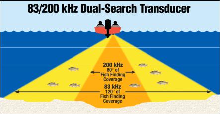
Dual Search Transducer
Your unit is packed with a Dual Search Skimmer Transducer that can transmit at 83 kHz and 200 kHz.
A new innovation, the 83 kHz frequency offers superior sonar performance at all depths from very shallow up to 1,000 ft and provides up to 120º of fishfinding coverage.
Preparations
The following shows the recommended sequence for installing the transducer:
CAUTION:
You should read over this entire installation section before drilling any holes in your vehicle or vessel!
1.Determine the approximate location for the sonar unit, so you can plan how and where to route the cables for the transducer and power. This will help you make sure you have enough cable length for the desired configuration.
2.Determine the approximate location for the transducer and its cable route.
3
3.Determine the location of your battery or other power connection, along with the power cable route.
4.Install the transducer and route the transducer cable to the sonar unit.
5.Route the power cable from the unit's location to an appropriate power source and connect it there.
6.Connect the transducer/power cable to the unit and mount the sonar unit on the bracket.
Installation
These instructions will help you install your Skimmer transducer on a transom, on a trolling motor or inside a hull. Please read all instructions before proceeding with any installation. Your Skimmer transducer typically comes packaged with a one-piece stainless steel bracket for mounting it to the transom of your boat. The trolling motor mount uses a onepiece plastic bracket with an adjustable strap.
These are all "kick-up" mounting brackets. They help prevent damage if the transducer strikes an object while the boat is moving. If the transducer does "kick-up," the bracket can easily be pushed back into place without tools.
Depending on your sonar unit's connectors, your transducer cable may also have the sonar unit's power cable attached to it. If that is the case, be sure to install the transducer first, before connecting the power cable to a power source. See the instructions later in this manual for connecting the power cable to a battery or other power supply.
Read these instructions carefully before attempting the installation. Determine which of the mounting positions is right for your boat. Use extreme care if mounting the transducer inside the hull, because once it is epoxied into position, the transducer usually cannot be removed.
Remember, the transducer installation is the most critical part of a sonar installation.
Recommended Tools and supplies
If you prefer the option of routing the cable through the transom, you will need a 5/8" drill bit. Each transom mount requires use of a high quality, marine grade aboveor below-waterline caulking compound.
NOTE:
The following installation types also call for these recommended tools and required supplies (supplies are not included):
4
Single-frequency transom installations
Tools include: two adjustable wrenches, drill, #29 (0.136") drill bit, flathead screwdriver (for mounting screws and their pilot holes). Supplies: none.
Single-frequency trolling motor installations
Tools: two adjustable wrenches, flat-head screwdriver. Supplies: plastic cable ties.
Shoot-through hull installations
Tools: these will vary depending on your hull's composition. Consult your boat dealer or manufacturer. Supplies: 100 grit sandpaper, specially formulated epoxy adhesive available from LEI (see ordering information on the inside back cover). A sandwich hull also requires polyester resin.
Selecting a Transducer Location
1.The location must be in the water at all times, at all operating speeds.
2.The transducer must be placed in a location that has a smooth flow of water at all times. If the transducer is not placed in a smooth flow of water, interference caused by bubbles and turbulence will show on the sonar's display in the form of random lines or dots whenever the boat is moving.
NOTE:
Some aluminum boats with strakes or ribs on the outside of the hull create large amounts of turbulence at high speed. These boats typically have large outboard motors capable of propelling the boat at speeds faster than 35 mph. Typically, a good transom location on aluminum boats is between the ribs closest to the engine.
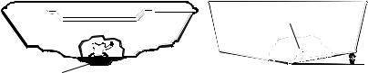
3. The transducer should be installed with its face pointing straight down, if possible. For shoot-thru applications: Many popular fishing boat hulls have a flat keel pad that offers a good mounting surface. On vee hulls, try to place the transducer where the deadrise is 10° or less.
Deadrise less than 10°
 Strakes
Pad
Vee pad hull (left); Vee hull (right). A pod style transducer is shown here, but the principle is the same for Skimmers inside a hull.
4. If the transducer is mounted on the transom, make sure it doesn't interfere with the trailer or hauling of the boat. Also, don't mount it closer than approximately one foot from the engine's lower unit. This will prevent cavitation (bubble) interference with propeller operation.
5
5. If possible, route the transducer cable away from other wiring on the boat. Electrical noise from engine wiring, bilge pumps and aerators can be displayed on the sonar's screen. Use caution when routing the transducer cable around these wires.
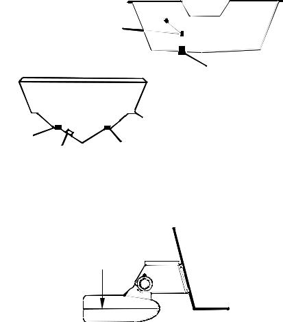
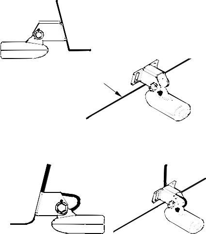
CAUTION: Clamp the transducer cable to transom near the transducer. This will help prevent the transducer from entering the boat if it is knocked off at high speed.
Good location
|
Poor location |
Good |
|
location |
Good location |
Poor angle |
Good and poor transducer locations.
How low should you go?
For most situations, you should install your Skimmer transducer so that its centerline is level with the bottom of the boat hull. This will usually give you the best combination of smooth water flow and protection from bangs and bumps.
Transom
Transducer centerline
Hull bottom
Align transducer centerline with hull bottom.
There, however, are times when you may need to adjust the transducer slightly higher or lower. (The slots in the mounting brackets allow you to loosen the screws and slide the transducer up or down.) If you frequently lose bottom signal lock while running at high speed, the transducer may be coming out of the water as you cross waves or wakes. Move the transducer a little lower to help prevent this.
6
If you cruise or fish around lots of structure and cover, your transducer may be frequently kicking up from object strikes. If you wish, you may move the transducer a little higher for more protection.
There are two extremes you should avoid. Never let the edge of the mounting bracket extend below the bottom of the hull. Never let the bottom – the face – of the transducer rise above the bottom of the hull.
Shoot-Thru-Hull vs. Transom Mounting
In a shoot-thru-hull installation, the transducer is bonded to the inside of the hull with epoxy. The sonar "ping" signal actually passes through the hull and into the water. This differs from a bolt-thru-hull installation (often called "thru-hull"). In that case, a hole is cut in the hull and a specially designed transducer is mounted through the hull with a threaded shaft and nut. This puts the transducer in direct contact with the water.
Typically, shoot-thru-hull installations give excellent high speed operation and good to excellent depth capability.
There is no possibility of damage from floating objects. It can't be knocked off when docking or loading on the trailer.
However, the shoot-thru-hull installation does have its drawbacks. First, some loss of sensitivity does occur, even on the best hulls. This varies from hull to hull, even from different installations on the same hull. This is caused by differences in hull lay-up and construction.
Second, the transducer angle cannot be adjusted for the best fish arches. This can be a problem on hulls that sit with the bow high when at rest or at slow trolling speeds.
Third, a transducer CAN NOT shoot through wood and metal hulls. Those hulls require either a transom mount or a thru-hull installation.
Fourth, a Skimmer transducer with a built-in temp sensor will show only the temperature of the bilge, not the water surface temp.
Follow the procedure listed in the shoot-thru-hull installation section at the end of this lesson to determine if you can satisfactorily shoot through the hull.
Transom Transducer Assembly and Mounting
The best way to install these transducers is to loosely assemble all of the parts first, place the transducer's bracket against the transom and see if you can move the transducer so that it's parallel with the ground.
1. Assembling the bracket. Press the two small plastic ratchets into the sides of the metal bracket as shown in the following illustration. Notice there are letters molded into each ratchet.
7
Place each ratchet into the bracket with the letter "A" aligned with the dot stamped into the metal bracket.
This position sets the transducer's coarse angle adjustment for a 14° transom. Most outboard and stern-drive transoms have a 14° angle.
Dot
Align plastic ratchets in bracket.
2. Aligning the transducer on the transom. Slide the transducer between the two ratchets. Temporarily slide the bolt though the transducer assembly and hold it against the transom. Looking at the transducer from the side, check to see if it will adjust so that its face is parallel to the ground. If it does, then the "A" position is correct for your hull.
If the transducer's face isn't parallel with the ground, remove the transducer and ratchets from the bracket. Place the ratchets into the holes in the bracket with the letter "B" aligned with the dot stamped in the bracket.
Reassemble the transducer and bracket and place them against the transom. Again, check to see if you can move the transducer so it's parallel with the ground. If you can, then go to step 3. If it doesn't, repeat step 2, but use a different alignment letter until you can place the transducer on the transom correctly.
Ratchets
Insert bolt and check transducer position on transom.
8
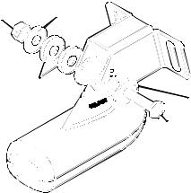
3. Assembling the transducer. Once you determine the correct position for the ratchets, assemble the transducer as shown in the following figure. Don't tighten the lock nut at this time.
Nut |
Metal |
|
washer |
||
|
Rubber |
|
washers |
Metal washer |
|
Bolt |
Assemble transducer and bracket.
4. Drilling mounting holes. Hold the transducer and bracket assembly against the transom. The transducer should be roughly parallel to the ground. The transducer's centerline should be in line with the bottom of the hull. Don't let the bracket extend below the hull!
Mark the center of each slot for the mounting screw pilot holes. You will drill one hole in the center of each slot.
Drill the holes. Use the #29 bit (for the #10 screws).
9
Transom
Transom
Position transducer mount on transom and mark mounting holes. Side view shown at left and seen from above at right.
5. Attaching transducer to transom. Remove the transducer from the bracket and re-assemble it with the cable passing through the bracket over the bolt as shown in the following figures.
Route cable over bolt and through bracket. Side view shown (left) and seen from above (right).
Attach the transducer to the transom. Slide the transducer up or down until it's aligned properly with the bottom of the hull as shown in the preceding and following figures. Tighten the bracket's mounting screws, sealing them with the caulking compound.
Adjust the transducer so that it's parallel to the ground and tighten the nut until it touches the outer washer, then add 1/4 turn. Don't over tighten the lock nut! If you do, the transducer won't "kick-up" if it strikes an object in the water.
10
Bottom of hull
Flat-bottom hull Deep-"vee" hull
Align transducer centerline with hull bottom and attach to transom.
6. Route the transducer cable through or over the transom to the sonar unit. Make sure you leave some slack in the cable at the transducer. If possible, route the transducer cable away from other wiring. Electrical noise from the engine's wiring, bilge pumps, VHF radio wires, cables and aerators can be picked up by the sonar. Use caution when routing the transducer cable around these wires.
WARNING:
Clamp the transducer cable to the transom close to the transducer. This can prevent the transducer from entering the boat if it is knocked off at high speed.
If you need to drill a hole in the transom to pass the connector through, the required hole size is 5/8". (If you intend to route an additional speed or temp sensor cable through the same hole, you will need a 1" (25.4 mm) drill bit instead.)
Caution:
If you drill a hole in the transom for the cable, make sure it is located above the waterline. After installation, be sure to seal the hole with the same marine grade aboveor below-waterline sealant used for the mounting screws.
7.Make a test run to determine the results. If the bottom is lost at high speed, or if noise appears on the display, try sliding the transducer bracket down. This puts the transducer deeper into the water, hopefully below the turbulence causing the noise. Don't allow the transducer bracket to go below the bottom of the hull!
11
Trolling Motor Bracket Installation
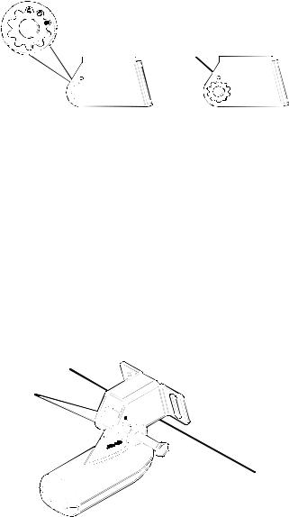
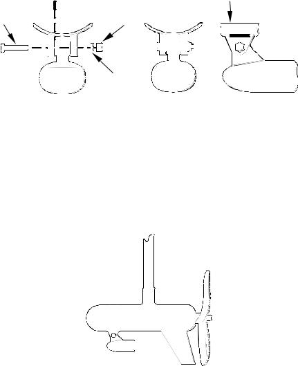
1. Attach the optional TMB-S bracket to the transducer as shown in the following figure, using the hardware supplied with the transducer. (Note: The internal tooth washer is supplied with the TMB-S.)
TMB-S bracket

 Internal tooth washer
Bolt |
Nut |
Flat washer
Attach motor mounting bracket to transducer.
2. Slide the adjustable strap supplied with the TMB-S through the slot in the transducer bracket and wrap it around the trolling motor.
Position the transducer to aim straight down when the motor is in the water. Tighten the strap securely.
3. Route the transducer cable alongside the trolling motor shaft. Use plastic ties (not included) to attach the transducer cable to the trolling motor shaft. Make sure there is enough slack in the cable for the motor to turn freely. Route the cable to the sonar unit and the transducer is ready for use.
Transducer mounted on trolling motor, side view.
12
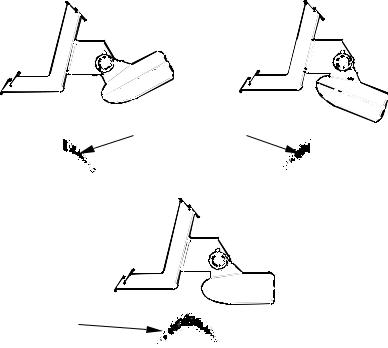
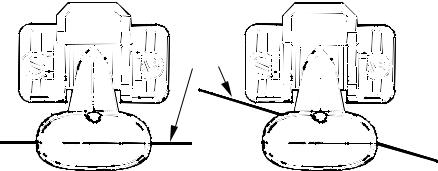
Transducer Orientation and Fish Arches
If you do not get good fish arches on your display, it could be because the transducer is not parallel with the ground when the boat is at rest in the water or at slow trolling speeds.
|
Partial fish arches |
Transducer aimed |
Transducer aimed |
too far back |
too far forward |
Full fish arch
Proper transducer angle
Transducer angles and their effects on fish arches.
If the arch slopes up – but not back down – then the front of the transducer is too high and needs to be lowered. If only the back half of the arch is printed, then the nose of the transducer is angled too far down and needs to be raised.
NOTE:
Periodically wash the transducer's face with soap and water to remove any oil film. Oil and dirt on the face will reduce the sensitivity or may even prevent operation.
Shoot-Thru-Hull Preparation
Hulls with Flotation Materials
The transducer installation inside a fiberglass hull must be in an area that does not have air bubbles in the resin or separated fiberglass lay-
13
 Loading...