


LMS-350A
INSTALLATION AND OPERATION
INSTRUCTIONS

IMPORTANT!
YOU MUST HAVE THE OPTIONAL LGC-1 GPS MODULE ATTACHED TO THE LMS-350A TO USE THE POSITION AND NAVIGATION FEATURES ON THIS PRODUCT.
WARNING!
USE THIS PRODUCT ONLY AS AN AID TO NAVIGATION. A CAREFUL NAVIGATOR NEVER RELIES ON ONLY ONE METHOD TO OBTAIN POSITION INFORMATION.
CAUTION
The LGC-1 GPS receiver, (like all GPS navigation equipment) will show the shortest, most direct path to a waypoint. It provides navigation data to the waypoint regardless of obstructions. Therefore, the prudent navigator will not only take advantage of all available navigation tools when travelling to a waypoint, but will also visually check to make certain a clear, safe path to the waypoint is always available.
NOTICE!
As of this writing, the Department of Defense (DOD) has not declared the GPS navigation system operational. The system is still in a testing phase. Satellites can be turned off or accuracy can be degraded at will by the system operators. Remember that the LMS-350A, or any GPS receiver is only as accurate as the system it’s using.
Copyright © 1993 Lowrance Electronics
All rights reserved.
All features and specifications subject to change without notice. All screens in this manual are simulated.

SONAR TABLE OF CONTENTS |
|
INTRODUCTION ............................................................................................................................ |
1 |
MOUNTING .................................................................................................................................... |
1 |
POWER CONNECTIONS ............................................................................................................... |
3 |
TRANSDUCER CONNECTIONS .................................................................................................... |
4 |
OPTIONAL GPS MODULE INSTALLATION ................................................................................... |
5 |
KEYBOARD BASICS ...................................................................................................................... |
8 |
DISPLAY ......................................................................................................................................... |
9 |
MENUS .......................................................................................................................................... |
10 |
HELP .............................................................................................................................................. |
10 |
WINDOWS ..................................................................................................................................... |
10 |
VIEWING WINDOWS OPTIONS ............................................................................................... |
12 |
MODIFYING GROUPS .............................................................................................................. |
12 |
RESETTING ALL GROUPS ...................................................................................................... |
13 |
SONAR OPERATION .................................................................................................................... |
14 |
AUTOMATIC .................................................................................................................................. |
14 |
SENSITIVITY ................................................................................................................................. |
15 |
RANGE .......................................................................................................................................... |
16 |
ZOOM - Automatic Operation ........................................................................................................ |
17 |
ZOOM - Manual Operation ............................................................................................................. |
18 |
MENU - PAGE 1 ............................................................................................................................ |
19 |
CHART SPEED ......................................................................................................................... |
19 |
GRAYLINE® .............................................................................................................................. |
19 |
FISH I.D. .................................................................................................................................... |
20 |
DISPLAY CONTRAST ............................................................................................................... |
21 |
ALARMS .................................................................................................................................... |
22 |
FISH ALARM .......................................................................................................................... |
22 |
DEPTH ALARMS .................................................................................................................... |
23 |
ZONE ALARM ........................................................................................................................ |
24 |
SONAR FREQUENCY ................................................................................................................... |
25 |
DUAL FREQUENCY OPERATION ............................................................................................ |
26 |
MENU - PAGE 2 ............................................................................................................................ |
27 |
ADJUST BACK LIGHT LEVEL................................................................................................... |
27 |
BACK LIGHT ON/OFF ............................................................................................................... |
27 |
SPEAKER VOLUME .................................................................................................................. |
27 |
TURN DIGITAL BOX OFF ......................................................................................................... |
28 |
CONSTRUCT DIGITAL BOX ..................................................................................................... |
28 |
MENU - PAGE 3 ............................................................................................................................ |
29 |
DISPLAY ZOOM BAR ................................................................................................................ |
29 |
DISPLAY ZONE BAR ................................................................................................................. |
29 |
DIGITAL SONAR ....................................................................................................................... |
30 |
TURN ALL SONAR OFF ........................................................................................................... |
30 |
CHART CURSOR ...................................................................................................................... |
30 |
MENU - PAGE 4 ............................................................................................................................ |
30 |
FASTRAK .................................................................................................................................. |
31 |
SELECT UNITS OF MEASURE ................................................................................................. |
31 |
CLEAR DISTANCE LOG ........................................................................................................... |
32 |
DEPTH LINES ........................................................................................................................... |
32 |
MENU - PAGE 5 ............................................................................................................................ |
33 |
ADJUST CHART SURFACE CLARITY ..................................................................................... |
33 |
ADVANCED SIGNAL PROCESSING (ASP) .............................................................................. |
34 |
SYSTEM INFORMATION .......................................................................................................... |
34 |
PRESET SONAR AND GPS ...................................................................................................... |
35 |
MENU - PAGE 6 ............................................................................................................................ |
35 |
ADJUST KEEL OFFSET ............................................................................................................ |
35 |
CALIBRATE SPEED .................................................................................................................. |
36 |
BATTERY BACKUP ................................................................................................................... |
37 |
TRANSDUCERS AND CONE ANGLES ......................................................................................... |
38 |
FISH ARCHES ............................................................................................................................... |
39 |
SONAR TROUBLESHOOTING ..................................................................................................... |
40 |
WINDOWS GROUP SUMMARY .................................................................................................... |
44 |
WINDOWS SUMMARY .................................................................................................................. |
47 |

INTRODUCTION
The LMS-350A is a high quality, wide screen sonar with performance that is second to none in its class. Using menu features and “soft-key” operation, the LMS-350A is also one of the easiest-to-use sonars that Lowrance has ever built. The wide “ClearVision” screen shows the underwater world with high resolution and detail. The display and keyboard are also lighted for night operation. The LMS-350A also has digital depth, boat speed, surface water temperature, and distance travelled (log) displays (requires an optional ST-T speed/temperature sensor).
If you purchase and install a LGC-1 GPS module, the LMS-350A can show position and navigation information. Utilizing Rockwell's NavCoreV technology, this GPS receiver is second to none in it's class.
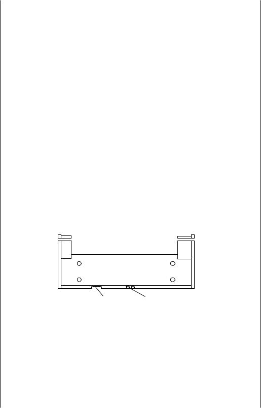
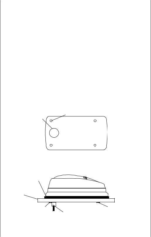
MOUNTING - Bracket Mount
The LMS-350A can be mounted on it's gimbal bracket or in-dash mounted. Brackets are supplied for both configurations, however if the dash is thicker than 1/2", a special bracket will have to be purchased to mount the unit in the dash. You can install the LMS-350A on its bracket in any convenient location, provided there is clearance behind the unit when it is tilted for the best viewing angle. Holes in the bracket base allow wood screw or through-bolt mounting. You may need to place a piece of plywood on the back of thin fiberglass panels to secure the mounting hardware. Make certain there is enough room behind the unit to attach the power and transducer cables.
FRONT
SLOT |
BREAK |
|
OUT SLOT |
You will need to drill a hole in the dash for the power and transducer cables. The smallest hole that will pass one power or transducer plug is one inch. After the hole is drilled, pass the transducer connector up through the hole first, then pass the power cable down through it.
After the cables have been routed, fill the hole with a good marine sealing compound. Offset the bracket to cover the hole. Route the power cable through the slot and break out one of the other slots in the bracket for the transducer cable.
1
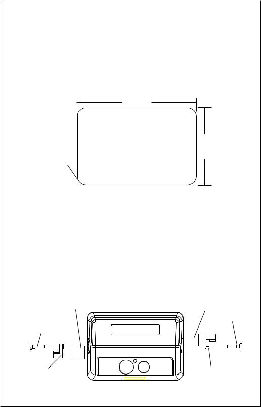
IN-DASH MOUNTING
The LMS-350A can be installed in the dash with the supplied hardware if the dash is 1/2" thick or less. Determining the dash thickness can be difficult, however, if you remove a gauge from the dash, you can easilly measure the thickness. Try this in an area that's close to the location that you wish to install the unit, since the thickness can vary significantly in some boats. Make certain there is clearance behind the dash for the unit and there is enough room to tighten the bolts on both sides of the unit.
.400" radius (4 places)
7.625"
DASH CUTOUT
5.375"
Once you've determined the location for the unit, cut the hole according to the drawing shown above. Measure carefully before cutting! After cutting the dash, place the gasket supplied with the LMS-350A around the unit and place the unit in the hole.
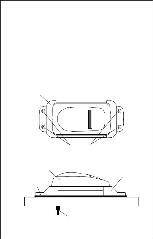
Supplied with the LMS-350A are rubber pads, bolts, washers, and cam clamps to attach the LMS-350A to the dash. Peel the adhesive backing off the rubber pads and place one on each side of the LMS-350A in the location where the cam clamp will touch the back side of the dash. Using the hardware supplied with the unit, attach the LMS-350A to the dash. Make certain that the cam clamp on the left side of the unit is pointing down and the cam clamp on the right side of the unit is pointing up before you start tightening the bolts.
RUBBER PAD |
RUBBER PAD |
|
BOLT |
BOLT |
LOWRANCE |
CAM CLAMP |
CAM CLAMP |
(TURNED DOWN) |
(TURNED UP) |
2
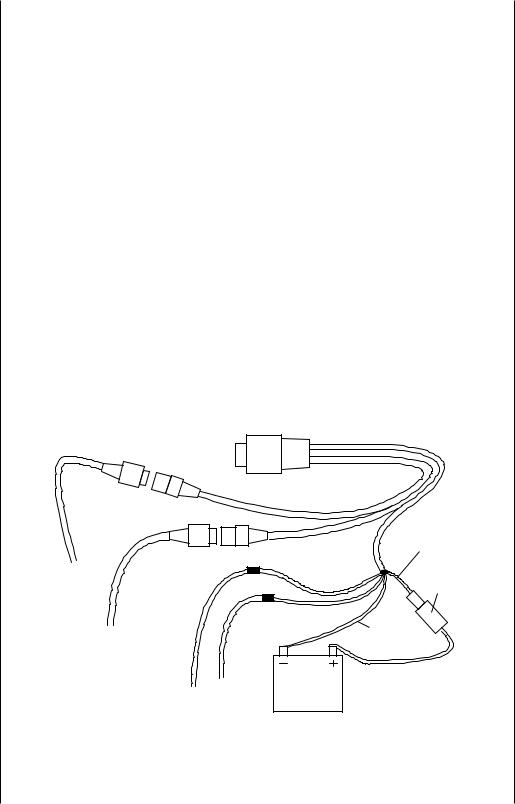
POWER CONNECTIONS
The LMS-350A works from a twelve-volt battery system. For the best results, attach the power cable directly to the battery. You can attach the power cable to an accessory or power buss, however you may have problems with electrical interference. Therefore, it’s safer to go ahead and attach the power cable directly to the battery. If the cable is too short, splice #18 gauge wire onto it. The power cable has four wires; red, black, green, and white. Red is the positive lead, black is negative or ground. Make certain to attach the in-line fuse holder to the red lead as close to the power source as possible. For example, if you have to extend the power cable to the battery or power buss, attach one end of the fuse holder directly to the battery or power buss. This will protect both the unit and the power cable in the event of a short. The LMS-350A uses a 3-amp fuse.
IMPORTANT!
Do not use this product without a 3-amp fuse wired into the power cable! Failure to use a 3-amp fuse will void your warranty.
If you’re installing an optional speed/temperature sensor, read the speed/ temperature sensor's installation manual for mounting instructions. Route the sensor’s cable to the LMS-350's power cable and plug it into the connector marked “SPEED/TEMP CABLE”
TO "P" CONNECTOR
ON ACCURA
|
RED |
|
WIRE |
TO |
3 amp |
GPS |
FUSE |
MODULE |
|
|
BLACK |
TO |
WIRE |
SPEED/ |
|
TEMP |
|
SENSOR |
12 VOLT |
TO |
|
NMEA |
BATTERY |
INTERFACE |
|
LMS-350A POWER CONNECTIONS
3
The white wire is for a NMEA interface. The LMS-350A sends data to another electronic navigation devices through the white wire. It receives data from a differential (DGPS) beacon receiver through the green wire. If the white and green wires are not used, tape their ends so that they cannot short.
To connect a device to the LMS-350's NMEA output (white wire), attach a shielded, twisted pair cable from the device's NMEA intput to the white wire on the LMS-350's power cable. Solder the ground conductor of the twisted pair and the shield to the black wire on the power cable. Do not connect the shield to the other device. Use the green and black wires in the same manner to attach a DGPS recevier's output to the LMS-350's input (green wire). See the other instrument's manual and the NMEA section in this manual for more information.
TRANSDUCER CONNECTIONS
The LMS-350A has dual frequency capability. It can operate at 50 or 192 kHz, separately, or at the same time. The connection diagram below shows the proper method to attach the transducers to the LMS350A. See the transducer owner’s manual for transducer installation instructions. If dual frequency (simultaneous) operation is desired, a 50 kHz transducer and the MY-2 transducer adapter cable must be purchased separtately.
See page 18 for more information on dual frequency operation.
DUAL |
"T" CONNECTOR ON |
|
FREQUENCY |
LMS-350A |
|
SINGLE FREQUENCY |
TRANSDUCER |
|
ADAPTER |
||
|
||
"T" CONNECTOR ON |
CABLE |
|
(MY-2) |
||
LMS-350A |
||
|
192 kHz |
50 kHz |
TRANSDUCER |
TRANSDUCER |
 192 kHz or 50 kHz
TRANSDUCER
4
OPTIONAL GPS MODULE INSTALLATION
The GPS module can be installed on a flat surface or (with the supplied adapter) on a pole. Mount the module in an area that guarantees a clear view of the sky at all times. In order for the module to receive the signals from the satellites, it must not be obstructed. An ideal location is on a cabin roof, or deck. The gunnels also make a good location. Attaching the pole mounting adapter lets you install the module on a one inch mast. However, for lightning protection, the antenna shouln't be the highest part of the boat.
Surface Mounting - With Access
If you have access underneath the mounting surface, use the gasket supplied with the GPS module as a template. Drill four 5.5 mm (7/32") holes and one 17 mm (11/16") hole for the module's cable. Attach the cable to the module and pass it down through the hole in the gasket and the mounting surface. Use 5 mm screws, flat washers, and lock washers to fasten the GPS module to the mounting surface. Route the cable to the LMS-350A.
|
5.5 mm (7/32") |
17mm |
Hole |
(11/16") |
(4 places) |
Hole |
|
GASKET
DECK
12345678901234567890123456789012123456
1234567890123456789012345678901212345 6
5 MM SCREWS |
|
5 MM SCREWS |
|
CABLE
5
Surface Mounting - Without Access
If you don't have access to the back side of the mounting surface, use the "cleats" supplied with the LMS-350A. (Note: This is assuming you can "snake" the module's cable to a location that is accessable. A hole will still need to be drilled in the mounting surface for the cable.) Using the gasket as a template, mark and drill the 17 mm (11/16") hole for the cable. Attach the cable to the module and drop the other end of the cable through the gasket and down the hole. Place the module on the gasket. Slide the "cleats" onto each end of the module and (using the cleats as templates) mark four holes for 5 mm (#10) mounting screws. Drill the holes, then replace the cleats on the module and fasten them to the mounting surface with 5 mm (#10) screws. Route the cable to the LMS-350A.
"CLEAT"
MARK AND
DRILL FOUR
PLACES
GPS MODULE
"CLEAT"
GASKET
2345678901234567890123456789012123456789012345678901234
234567890123456789012345678901212345678901234567890123
234567890123456789012345678901212345678901234567890123
234567890123456789012345678901212345678901234567890123
CABLE
6
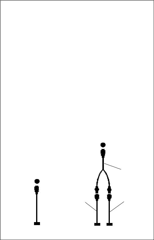
Pole Mount
First, thread the pole mounting adapter onto the mounting pole or ratchet base. Align the pole mounting adapter so the module will face the bow of the boat. Install and tighten the set screw into the pole mounting adapter and tighten it securely. This should prevent the GPS module from unscrewing from the pole. Place the gasket onto the pole mounting adapter. Now attach the cable to the GPS module and pass the cable through the gasket, pole mounting adapter, and pole. Set the GPS module on top of the pole mounting adapter and align the four threaded holes in the module with the holes in the pole mounting adapter. Using the four stainless steel 5 mm screws and lock washers supplied with the LMS-350A, attach the pole mounting adapter to the GPS module. This completes the assembly.
GPS MODULE
POLE
MOUNTING
ADAPTER
SET |
POLE |
|
SCREW |
||
|
If the pole or mast you're using isn't hollow or if the hole in the middle of the pole is too small for the connectors, use the cable mounting adapter supplied with your unit. Thread the cable mounting adapter into the GPS pole mounting adapter. Then thread the pole into the cable mounting adapter. Route the cable down the outside of the pole.
GPS MODULE
CABLE |
CABLE |
|
MOUNTING |
||
MOUNTING |
||
ADAPTER |
||
ADAPTER |
||
|
||
POLE |
POLE |
|
|
7
LOWRANCE LMS-350A
1 2 3
SENS
4 5 6
RANGE
7 8 9
ZOOM
CLR 0 ENT
AUTO
WAYPT
WAYPT
MENU |
EVENT |
MAN |
|
MARKER OVERBOARD |
|
OFF |
ON |
|
SONAR GPS PLOTTER WINDOWS |
|
|
KEYBOARD
The keyboard has keys arranged in a vertical column on the left plus a horizontal row at the bottom. A ten-key pad and arrow keys on the right side of the screen lets you enter and change data on the screen. The keys in the left column are used for sonar and menu selections. The menu key in the bottom left corner of the keyboard activates the first menu page. The keys along the bottom of the screen are used to switch between the sonar, optional GPS, and windows modes.
SONAR - Press this key to switch to the sonar display.
GPS - The GPS navigation displays show when you press this key.
PLOTTER - Press this key to show the GPS Plotter display.
WINDOWS - This key gives you access to the windows mode, which lets you customize displays.
SENS - Press this key to adjust the unit’s sonar sensitivity.
RANGE - This key lets you adjust the sonar's range.
ZOOM - The LMS-350A gives you 2X and 4X zoom capability with this key.
AUTO - This turns the automatic feature off and on.
WAYPT - Press this key to save and recall waypoints.
8
WAYPT QUICK SAVE - Pressing this key instantly saves your position.
MENU - Press this key to show the menus and gain access to most functions.
CLR - This key clears menus and erases entries from the screen.
ENT - This key is used to enter numbers and make selections.
ARROW KEYS - These keys are used to make menu selections and to move objects on the screen.
ON - The ON key turns the LMS-350A on.
OFF - Press and HOLD the Off key to turn the LMS-350A off.
DISPLAY - General
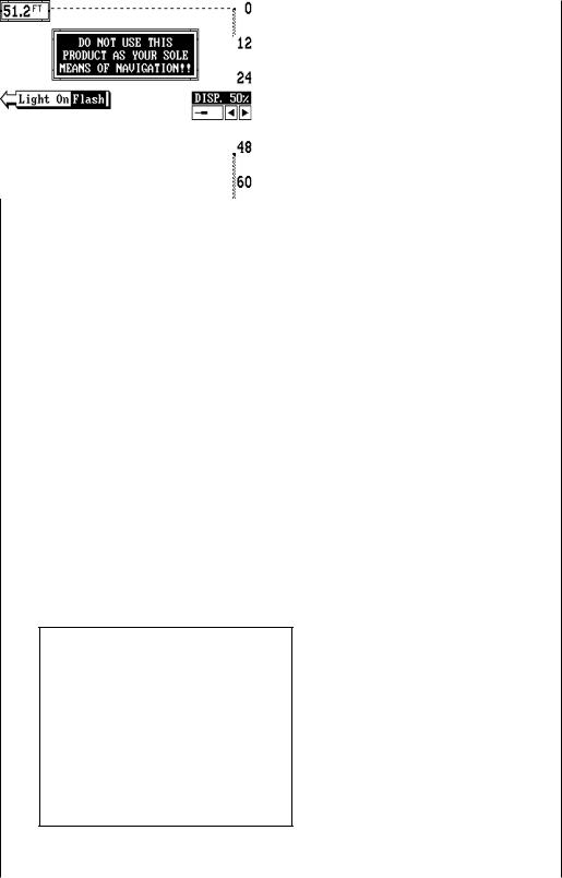
The lights are turned on for approximately ten seconds when the LMS350A is first turned on. Menus appear at the same time. To keep the lights on, press the key adjacent to the Light label. It controls the backlighting used on the display and keyboard. If you don’t want the lights on, wait ten seconds and the lights will automatically turn themselves off. The menus will also disappear after ten seconds, or you can turn them off by pressing the CLR key on the left side of the zero (0) key.
The Metric label at the top of the screen works the same way. Press the key adjacent to the Metric label to change the depth from feet to meters. This also changes the temperature display to degrees Celsius, speed to knots, and log to kilometers.
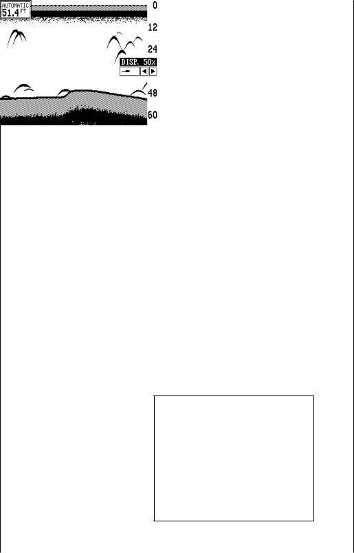
The Display menu on the right side of the screen let you adjust the display’s contrast for the best viewing angle. Pressing the left arrow key decreases the contrast, the right arrow increases it. After setting the contrast for the best viewing angle, press the CLR key to erase the menu or wait approximately ten seconds and it will automatically erase. See the Display Contrast section for more informa-
tion on this feature.
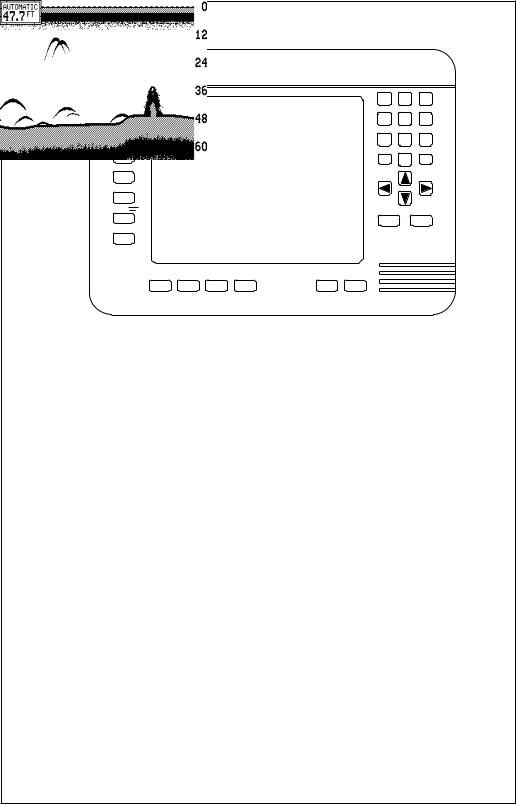
When the LMS-350A is first turned on, the display will appear similar to the one at left. The word “AUTOMATIC” in
9
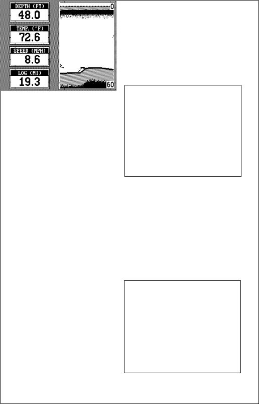
the upper left corner of the display indicates the automatic feature is on. The digital bottom depth also showsin this box.
MENUS
The LMS-350A uses menus extensively to guide you through the functions and features of the unit. The menu key accesses many of these features, allowing you to customize the unit to your particular needs and water conditions. Although you
may have to leave one menu and enter another to reach the desired function, all you have to do is press the key next to the "More" label to select the next menu. To return to the sonar screen, simply press the key next to the "Exit" label or press the CLR key.
HELP
An extremely useful feature incorporated into the LMS-350A series is the Help menus. Virtually every feature has a help menu label that, when pressed, gives one or more pages of text describing how to use that feature. For example, pressing the AUTO key brings up a menu letting you switch the unit into or out of the automatic mode. A help label also appears on the screen. Pressing the key adjacent to the help label gives you a description of how automatic works and how it affects different functions.
WINDOWS
You can change the displays on the LMS-350A by using the windows feature. This lets you customize displays to your own fishing or boating situations. This feature gives
you 22 different window screens.
The screens available in the windows mode are divided into two or more windows per screen. Each screen of windows is called a “group”. Group “A” as shown at right has the digital displays in one window and the sonar chart in the other.
10

backward. For example, pressing the down arrow key once shows the group “B” screen. To return to the full sonar screen, press the “SONAR” key.
To use the windows feature, first press the WINDOWS key. A screen similar to the one shown at left appears. The menu on the right side of the screenletsyouswitchbetween the “pages” of displays. These are lettered “A” through “V”. Group “A” shows first. Press the down arrow key to move forward through the screens. Press the up arrow key to move
Every one of the group screens can be modified to some extent. For example, press the MENU key while group “A” is displayed. Three new labels
appear on the display as shown above. Two of these labels are window menus. Pressing the key adjacent to one of the “window menu” labels gives you a menu with functions that relate only to that window. For example, if you press the key adjacent to the window menu label on the sonar chart window, the screen will clear and you will have a new menu with selections such as “ADJUST CHART SPEED” and “ADJUST
GRAYLINE”. Other window menus let you change the sonar frequency or turn the Fish ID feature on.
To exit from a window menu,
11

press the CLR key.
VIEWING WINDOWS OPTIONS
To see all of the available window options, press the WINDOWS key, then press the MENU key. Now press the key adjacent to the “MAIN MENU” label. Finally, press the key next to the “VIEW ALL WINDOWS” label. The screen at right appears.
The first window appears in the upper right corner of the screen. A description of the screen shows in the box at the bottom of the screen. Now press the key adjacent to the “NEXT” label. This changes the displayed window and description.
When you’ve finished viewing the windows, press the CLEAR key.
MODIFYING GROUPS
To modify or “customize” a group, first press the WINDOWS key, then press the MENU key. Now press the key adjacent to the “MAIN MENU” label at the bottom of the screen. The screen shown at right appears.
Now press the key adjacent to the “RE-PROGRAM A GROUP” label. The screen shown below appears.
Select the letter of the group you wish to customize by pressing the key adjacent to the group’s label. If the label isn’t shown on this page, press the key adjacent to the “MORE” label. In this example, the key
12
next to the “GROUP A” label was pressed. The screen shown at the top of the next page appears.
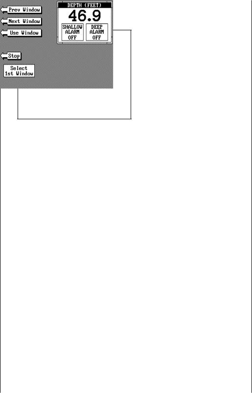
The depth window appears in the upper right corner of the screen. Press the key adjacent to the “NEXT WINDOW” label to move through the windows. If you reach the last window, or if you wish to go backwards through the windows, press the key next to the “PREV WIN-
DOW” label. When the desired window is on the screen, press the key next to the “USE WINDOW” label. The screen clears, placing the new window in the upper left corner of the screen. If the new window takes up half the screen, the unit will place it on the left side of the screen.
Continue with the window selections until the screen is filled. The unit will stay in the windows mode using your new customized screen. If you don’t want to fill a screen and only use one, two, or three windows in a group, simply press the key adjacent to the “STOP” label. This saves the group and exits the modify windows mode.
Remember, you can always return to the full screen sonar mode by pressing the “SONAR” key in the bottom left corner of the LMS350A. To switch back to your customized screen from the full screen sonar, simply press the WINDOWS key, then use the down arrow key to switch to the group you customized.
NOTE: The LMS-350A saves all window changes in memory. It keeps these changes even if power is turned off. However, a preset does erase all window changes and returns to the standard windows.
RESETTING ALL GROUPS
To return all of the groups to their factory settings without turning the unit off and on again, press the WINDOWS key, then press the MENU key, then press the key adjacent to the “MAIN MENU” label. Now press the key adjacent to the “RE-PROGRAM A GROUP” label. Finally, press the key
13
SONAR OPERATION
AUTOMATIC
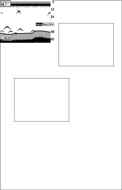
When the LMS-350A is first turned on, the Automatic feature is enabled. This is indicated by the word “AUTO” at the top of the screen. The Automatic feature adjusts the sensitivity and range so the bottom signal is displayed in the lower half of the screen at all times.
To turn Automatic off, first press the AUTO key. A menu appears at the bottom of the screen above the left and right arrows. Press the left arrow key to switch to the manual mode. The letters “Man” appear in the upper left corner of the display, indicating the unit is in the manual mode. To turn Automatic on, press the AUTO key again, then press the right arrow key.
Remember, when the LMS-350A is in the automatic mode, you have a limited adjustment range on the Sensitivity control and no control over the Range. Zoom adjusts differently in automatic than manual, also.
14
SENSITIVITY
The sensitivity key on the LMS-350A controls the ability of the unit to pick up echoes. A low sensitivity level excludes much of the bottom information, fish signals, and other target information. High sensitivity levels enables you to see this detail, but it can also clutter the screen with many undesired signals. Typically, the best sensitivity level shows a good solid bottom signal with Grayline and some surface clutter.
When the LMS-350A is in the Automatic mode, the sensitivity is automatically adjusted to keep a solid bottom signal displayed, plus a little more. This gives it the capability to show fish and other detail.
However, situations occur where it becomes necessary to increase or decrease the sensitivity. This typically happens when you wish to see more detail, so an increase in sensitivity is indicated. The procedure to adjust it is the same whether the unit is in the automatic or manual mode.
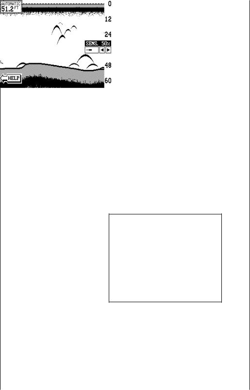
To adjust the sensitivity, press the SENS key. The sensitivity adjust menu appears on the right side of the screen.
The sensitivity menu has left and right arrows, plus a horizontal bar graph. The graph gives a visual indication of the sensitivity level. The number above the arrows also shows the percentage of sensitivity in use.
To increase the sensitivity level, press the right arrow key. As you press the key, the menu’s bar graph will grow wider and the percentage will increase in value. You can also see the difference on the chart record as it scrolls. When the sensitivity is at the desired level, release the key.
To decrease the sensitivity level, press the key adjacent to
the left arrow. The bar graph and percentage will decrease. When the sensitivity is at the desired level, release the key.
When you reach either the maximum or minimum limit, a tone sounds. To turn the menus off, press the CLR key or wait a few seconds and the menus will automatically disappear.
15
RANGE - Automatic
When turned on for the first time, the LMS-350A automatically places the bottom signal in the lower half of the screen. This is called Auto Ranging and is part of the automatic function. The range cannot be changed manually while the unit is in automatic.
RANGE - Manual
The LMS-350A gives you control over the range when it’s in the manual mode. There are two different methods used to change the range. The first way changes only the lower limit by pressing the arrow keys. On the screen shown below, the lower limit is 60 feet. The upper limit is zero. The secondmethodletsyouchange
both the upper and lower limits. This let's you create a "zoom" window down to five feet in virtually any combination of upper and lower limits. For example, a range with a 15 foot upper limit and a 45 foot lower limit creates a 30 foot zoom window. If the original range was zero to sixty feet, then this created a 2X zoom.
To change the range, first make certain the LMS-350A is in the manual mode. Next, press the RANGE key. The range adjustment menu appears on the right side of the display. To change only the lower limit, simply press the up or down arrow keys to decrease or increase the range. The available ranges are 0-5, 10, 20, 30, 40, 60, 100, 150, 200, 300, 500, 800, 1000, 1500, 2000, 3000, and 5000 feet. After the desired range is displayed, press the CLEAR key to erase the range menu.
NOTE: The maximum depth capability of the LMS-350A depends on the transducer installation, water and bottom conditions, and other factors. The performance of the LMS-350A will vary from day-to-day because of changing conditions.
16
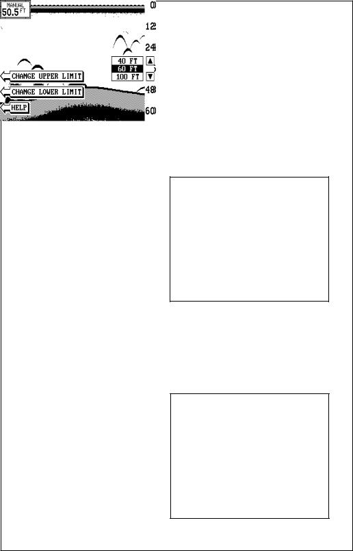
To change an upper or lower limit using the numbered keys, first press the RANGE key, then press the key next to either the "CHANGE UPPER LIMIT" or "CHANGE LOWER LIMIT" labels. On the screen shown at right, the key next to the "CHANGE UPPER LIMIT" was pressed. Now enter the desired depth, using the numbered keys. In this example, we en-
tered 35 feet. Now press the ENT key. The LMS-350A erases the range menus from the screen, and uses the new range you entered as shown below.
To change the lower limit, simply repeat the above steps, but press the key next to the "CHANGE LOWER LIMIT" label. Now enter the desired lower limit and press the ENT key. The LMS-350A erases the lower limit menus and changes the lower limit to the one you specified.
If you make a mistake while entering a limit, simply press the CLR key to erase the numbers. To exit from either the upper limit or lower limit entry screen, simply press the CLR key again.
ZOOM
Enlarging or “zooming” the picture is a common method used to show small detail and fish signals. The LMS-350A gives you two different zoom sizes, plus a split screen zoom option. The zoom operation and adjustment is different in the automatic and manual modes.
ZOOM - AUTOMATIC MODE
To zoom the display in the automatic mode, first press the ZOOM key. All targets on the display are enlarged four times normal size automatically. The menus shown at the top of the next page also appear.
17
next to the “RESET ALL GROUPS” label.
Turn the zoom feature on (or off) by pressing the key adjacent to the “OFF/ON” label.
Pressing the key adjacent to the “2X/4X” label enlarges echoes from two times to four times their normal size.
To switch between the split screen zoom and full screen zoom, press the key adjacent to the “SPLIT/FULL” label. The screen
instantly splits into two sections. All targets on the left are shown at four times the size of the ones on the right. If you switch to the 2X zoom mode, echoes on the left side of the screen are shown at twice the size as the ones on the right. The echoes that scroll across the screen are the exact same echoes on both sides of the screen. They’re simply enlarged on the left side. This feature tracks the bottom, keeping it on the display at all times, when the automatic feature is on. Once you’ve set the zoom as desired, press the CLR key to erase the menus.
ZOOM - MANUAL MODE
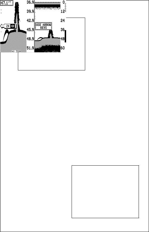
When you press the zoom key while the unit is in the manual mode, the screen shown below appears. All of the menus on this screen work identically as described above. However, one additional menu item is shown when the unit is in the manual mode: “ADJUST”.
To adjust the zoom, press the key adjacent to the “ADJUST” label. A screen similar to the one below appears. A zoom bar and adjust arrows appear on the screen. The echoes on the left side of the screen are the ones that appear between the
top and the bottom of the zoom bar. Press the up or down arrow keys to move the zoom bar up or down. As you adjust the zoom bar, the echoes move on the left side of the screen at the same time. The zoom adjust menus will automatically clear a few seconds after you’ve pressed the last key. Remember, the LMS-350A won’t track
18
the bottom when it’s in the manual mode.
MENU - PAGE 1
CHART SPEED
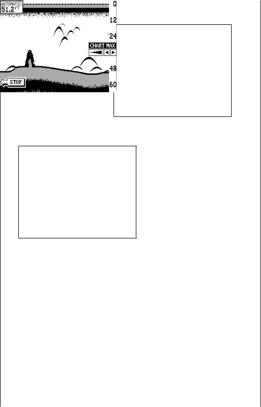
The rate echoes scroll across the screen is called the chart speed. It’s adjustable by first pressing the menu key, then pressing the key adjacent to the “Adjust Chart Speed” label. The chart speed menu appears
on the right side of the screen. Increase the chart speed by pressing the right arrow key or decrease it by pressing the left arrow key. The percentage of chart speed in use changes as the arrow keys are pressed. The bar chart also gives a graphical indication of the chart speed. You can see the change on the screen (both on the menu and on the chart record) as you press the keys. After you’ve made the adjustment, press the CLR key to erase the menu.
To stop the chart, press the key adjacent to the “STOP” label in the unit’s lower left corner. To start the chart, press the key next to the “START" label.
GRAYLINE®
GRAYLINE lets you distinguish between strong and weak echoes. It “paints” gray on targets that are stronger than a preset value. This allows you to tell the difference between a hard and soft bottom. For example, a soft, muddy or weedy bottom returns a weaker signal which is shown with a narrow or no gray line. A hard bottom returns a strong signal which causes a wide gray line.
If you have two signals of equal size, one with gray and the other without, then the target with gray is the stronger signal. This helps distinguish weeds from trees on the bottom, or fish from structure.
19
GRAYLINE® ON |
GRAYLINE® OFF |
GRAYLINE is adjustable. Since GRAYLINE shows the difference between strong and weak signals, adjusting the sensitivity may require a different GRAYLINE level, also. The level chosen by the LMS-350A at power on is usually adequate
for most conditions. Experiment with your unit to find the GRAYLINE setting that’s best for you.
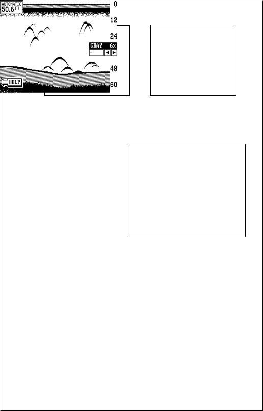
To adjust GRAYLINE, press the MENU key, then press the key adjacent to the “Adjust Chart Grayline” label. A screen similar to the one at right appears. Now press the left arrow key to decrease the gray level.
Press the right arrow key to increase it. The percentage of GRAYLINE in use changes as the arrow keys are pressed. The bar chart also gives a graphical indication of the GRAYLINE level. You can see the change on the screen (both on the menu and on the chart record) as you press the keys. After you’ve made the adjustment, press the CLR key to erase the menu.
FISH I.D.
The Fish I.D. feature identifies targets that meet certain conditions as fish. The micro-computer analyses all echoes and eliminates surface clutter, thermoclines, and other signals that are undesirable. In most instances, remaining targets are fish. The Fish I.D. feature displays symbols on the screen in place of the actual fish echoes. There are four fish symbol sizes: tiny, small, medium, and large. These are used to designate the relative size between targets. In other words, it displays a small fish symbol when it thinks a target is a small fish, a medium fish symbol on a larger target, etc.
20
outwards from a group of limbs is the hardest object for the Fish I.D. feature to distinguish from fish. You may see Fish I.D. symbols on the screen when actually, there are no fish. Practice with the unit in both the Fish I.D. mode and without to become more familiar with the Fish I.D. feature.
To turn the Fish I.D. feature on, press the menu key, then press the key adjacent to the “Turn Fish-ID On” label. Echoes will continue to scroll across the screen, however, the surface clutter at the top will no longer be displayed. Any targets the micro-computer determines are fish will be displayed as fish symbols. To turn the Fish I.D. feature off again, first press the menu key. Next, press the key adjacent to the “Turn Fish I.D. Off” label. The menu immediately disappears and the sonar screen returns.
Remember, the Fish I.D. feature can’t be used when the LMS-350A is in the manual mode. If you turn the Fish I.D. feature on when the LMS-350A is in manual, the micro-computer will turn the automatic feature on. If you turn automatic off when the Fish I.D. feature is on, the Fish I.D. feature will be turned off also.
The micro-computer is sophisticated, but it can be fooled. It cannot distinguish between fish and other suspended objects such as trotlines, turtles, submerged floats, air bubbles, etc. Individual tree limbs extending
DISPLAY CONTRAST
The unit’s display contrast is adjustable to suit different lighting conditions. To adjust it, first press the menu key. The first menu page appears. Now press the key next to the “Ad-
just Display Contrast” label. A screen similar to the one below appears. Now press the key adjacent to the left arrow to decrease the contrast. Press the key adjacent to the right arrow to increase it. The percentage of contrast in use changes as the arrow keys are
21
ALARMS
The LMS-350A has three different types of sonar alarms. The first is the Fish Alarm. It sounds when the Fish I.D. feature determines an echo or group of echoes is a fish. Another alarm is the Zone Alarm which consists of a bar. Any echo that appears inside this bar triggers the alarm. The last alarm is called the Depth Alarm. Only the bottom signal will trigger this alarm. This is useful as an anchor watch, a shallow water alert, or for navigation.
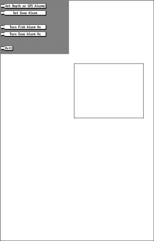
To adjust an alarm, first press the MENU key. Now press the key next to the "Adjust Alarms" label. The screen shown below appears. Press the key next to the “Set Depth or GPS Alarms” to adjust the shallow or deep digital alarms.Press the key next to the "Set Zone Alarm" to adjust the zone alarm. The fish alarm doesn't have an adjustment. It's either on or off.
The following section describes each sonar alarm and its limits.
FISH ALARM
Use the fish alarm for a distinctive audible alarm when fish or other suspended objects are detected by the Fish I.D. feature. A different tone sounds for each fish symbol size shown on the display.
To turn the fish alarm on, press the MENU key, then press the key next to the "Adjust Alarms" label. The screen shown above appears. Now press the key next to the "Turn Fish Alarm On" label.
To turn the fish alarm off, repeat the above steps. The label on the Alarms menu now reads "Turn Fish Alarm Off". Press the key next to that label to turn the fish alarm off.
22
DEPTH ALARMS
The depth alarms sound a tone when the bottom signal goes shallower than the shallow alarm’s setting or deeper than the deep alarm’s setting. For example, if you set the shallow alarm to ten feet, the alarm will sound a tone if the bottom signal is less than ten feet. It will continue to sound until you mute it or until the bottom goes deeper than 10 feet. The deep
alarm works just the opposite. It sounds a warning tone if the bottom depth goes deeper than the alarm's setting. Both depth alarms work only off the digital bottom depth signals. No other targets will trip these alarms. These alarms can be used at the same time or by themselves.
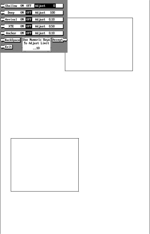
To set the depth alarms, first press the MENU key, then press the key next to the "Adjust Alarms" label. The screen on the previous page appears. Now press the key next to the "Set Depth Alarms" label. The screen at the top of this page appears.
To adjust the shallow alarm, press the key next to the "Shallow" label. To adjust the deep alarm, press the key next to the "Deep" label. Both alarms adjust identically. We'll use the shallow alarm as an example.
Pressing the key next to the "Shallow" label moves the black box from the "OFF" postion to the "Adjust". A new screen appears as shown at right. Use the numbered keypad on the right side of the unit to enter the shallow alarm setting. We used 10 feet in this example. After you've entered the desired alarm depth, press the ENT key. This enters the
alarm depth into memory. Now press the key next to the "Exit" label. The shallow alarm is now set. If the bottom goes shallower than 10 feet, the alarm will sound and a warning message appears on the screen at the same time. A label also appears letting you mute the alarm, if desired.
23
ZONE ALARM
The zone alarm consists of a bar that appears on the right side of the screen. Any echo that appears on the screen between the top and bottom of the zone alarm’s bar will “trip” the zone alarm.
Note: The zone alarm isn't available in the Windows mode.
To set the zone alarm, press
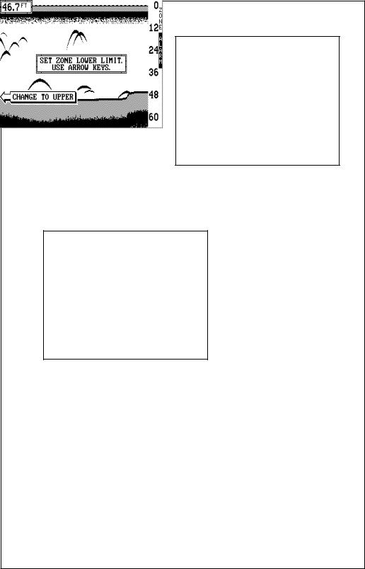
the MENU key. Now press the key next to the “Adjust Alarms” label. Finally, press the key next to the "Set Zone Alarm" label. A screen similar to the one shown below appears.
The zone alarm bar shows on the right side of the screen. Use the arrow keys to move the bottom of the bar higher or lower. To move the top of the bar, first press the key next to the “CHANGE TO UPPER” label. Now use the arrow keys to move the top of the bar higher or lower. When you have the zone alarm bar set as desired, press the CLR key to erase the menus.
The above steps automatically turn the zone alarm on if it was off. To turn the zone alarm off, press the MENU key, then press the key next to the "Adjust Alarms" label. Now press the key next to the "Turn Zone Alarm Off"label at the bottom of the screen.
Normally, the zone alarm bar disappears from the screen after you make adjustments. To leave the zone alarm bar on the screen all of the time, see the "Display Zone Alarm Bar" section in this manual for instructions.
24
 Loading...