


Operating Instructions
TV
■ Xelos A 42
■ Xelos A 37
■ Xelos A 32
■ Xelos A 26
233–32503.020
1

Contents
Remote control - TV functions
Control units
Connections - rear panel
Welcome
TV equipment
Scope of delivery
Transporting
Installation options
Notes on the screen
Cleaning
Disposal
For your safety
First installation
Remote control Connection
Handling the fabric hose
Using the common interface module Switching on
Automatic programming Directing DVB-T antenna
Daily operation
Switch on/off Changing stations
Basics about the menu operation For the info system
For the index Setting the sound Setting the picture
Direct control on TV set
Modes of operation
TV
How the colour keys work in TV mode Show status display
Calling the index
Standard settings pict.sound Call timer overview
Select picture format Move picture up/down TV menu
DVB subtitles CI module
Installing new DVB software
3 |
Picture in picture (PIP) |
25 – 26 |
||
4 – 5 |
|
PIP picture as freeze frame |
25 |
|
|
Selecting the station of the PIP picture |
25 |
||
6 – 8 |
|
|||
|
Selecting the station of the TV picture |
25 |
||
9 – 10 |
|
|||
|
Scan stations in the PIP picture |
25 |
||
9 |
|
|||
|
Interchanging PIP picture/TV picture |
25 |
||
9 |
|
|||
|
Functions in the PIP menu |
26 |
||
9 |
|
|||
|
Switch to small PIP |
26 |
||
9 |
|
|||
EPG - Programme guide |
27 – 28 |
|||
9 – 10 |
||||
|
Using the EPG |
27 |
||
10 |
|
|||
|
EPG menu |
28 |
||
10 |
|
|||
|
Selection of provider/station |
28 |
||
|
|
|||
11 |
|
Data entry |
28 |
|
12 – 14 |
Teletext |
29 – 30 |
||
|
Page selection |
29 |
||
12 |
|
|||
|
Displaying teletext pages |
29 |
||
12 – 13 |
|
|||
|
Programme timer recordings |
30 |
||
13 |
|
|||
|
Teletext menu |
30 |
||
13 |
|
|||
|
Digital teletext (UK only) |
30 |
||
13 |
|
|||
Radio |
31 |
|||
14 |
||||
|
|
|
||
15 |
Operating additional equipment |
32 – 34 |
||
15 – 20 |
Login and connect equipment |
32 |
||
Video playback |
33 |
|||
15 |
||||
Timer recording with video or DVD recorder |
33 |
|||
16 |
||||
Assignment of digital audio inputs and outputs |
34 |
|||
17 |
||||
Connect Loewe DVD Preceiver Auro 2216 PS |
35 |
|||
18 |
||||
Connecting other audio amplifiers or active speakers |
36 |
|||
19 |
||||
HDMI (DVI) connection |
37 |
|||
20 |
||||
VGA/XGA connection |
37 |
|||
20 |
||||
Component video connection |
38 |
|||
20 |
||||
Operating other devices with the remote control |
39 |
|||
21 – 28 |
||||
What to do, if ... |
40 – 41 |
|||
21 –24 |
||||
|
|
|
||
21 |
Technical data |
42 – 43 |
||
21 |
Accessories |
44 |
||
21 |
Service addresses |
45 – 46 |
||
22 |
||||
|
|
|
||
22 |
|
|
|
|
22 |
|
|
|
|
22 |
|
|
|
|
22 – 23 |
|
|
|
|
23 |
|
|
|
|
24 |
|
Dolby and the double ‘D‘ symbol are |
|
|
|
|
|||
24 |
|
|
||
|
|
trademarks of Dolby Laboratories |
|
|
2
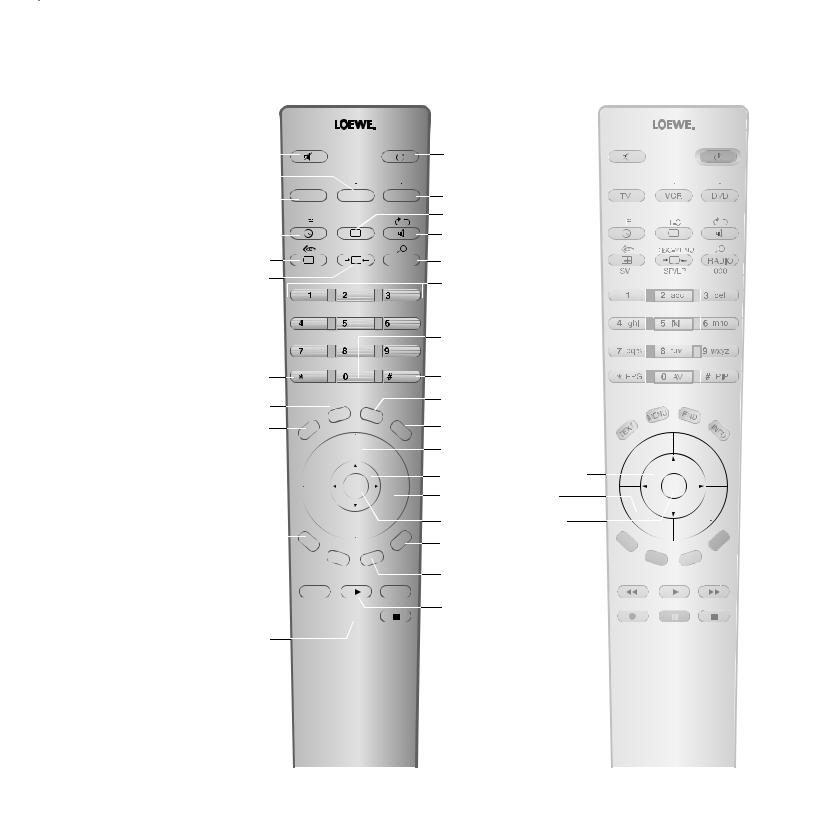
Remote control - TV functions
Sound off/on |
|
|
|
|
|
|
|
|
|
|
|
|
|
|
|
|
|
Switch over |
|
|
|
|
|
|
|
|
to operate VCR |
|
|
TV |
VCR |
DVD |
|||
Switch over |
|
|
||||||
|
||||||||
to opertae TV set |
|
|
|
|
|
|
|
|
Call timer list |
|
|
|
|
T-C |
|
|
|
|
|
|
|
|
|
|
||
|
|
|
|
|
|
|
||
|
|
|
|
|
|
|
|
|
|
|
|
|
|
|
|
|
|
Standard parameters for picture/sound /menu “Other functions” (3
Set picture format
|
|
|
|
|
DISC-MENU |
|
|
|
|
|
|
|
RADIO |
|
|
|
|
|
|
|
SV |
SP/LP |
000 |
||||
abc |
def |
ghi |
jkl |
mno |
pqrs |
tuv |
wxyz |
Switch on/off - on standby
Switch over
to operate DVD player
Picture menu on/off
Sound menu on/off
Radio on/off (2
Select station directly
/in the menu: enter numbers or letters
Call AV selection
Electronic Programme Guide Now&Next Programme info (3
Show/hide menu
Analogue Teletext on/off (3
EPG |
AV |
PIP |
|
N |
E |
|
|
|
E |
U |
|
N |
D |
|
M |
|
|
|
|
|
T |
I |
N |
|
X |
F |
E |
O |
T |
|
P+
PIP on/off (picture in picture)
Status display on/off (3 /in the menu: hide menu
Open index
/in the menu: info texts on/off P+/P– Select station up/down 


|
|
|
V– |
OK |
Red button:(3 |
P– |
|||
freeze picture on/off |
(1 |
|
|
|
|
|
|
|
|
Green button:(3
menu "Other functions"  on/off
Select station down (1 
 / in the Wizard: back
Direct recording (1 


Freeze picture on/off (1
(1 when equipped with Digital Recorder +, these
buttons have different functions, see operating instructions
of the Digital Recorder.
for PIP: Position of the PIP picture
/ in the menu: select/set
V+ 
V–/V+ Volume down/up
Station list on
/in the menu: confirm/call
Blue button:(3 programme info off/on
Yellow button:(3 previous station

 Select station up (1 Freeze picture off (1
 Freeze picture on (1
(2 Radio only for DVB reception if broadcast by the station.
(3 with DVB-T stations in UK different function The coloured keys do not work as described with DVB-T stations in UK, but they operate as described on page 30 (Digital Teletext).
– |
P |
+ |
|
P |
|
|
OK |
V |
+ |
– |
V |
|
Alternative remote control
3 |
3 |
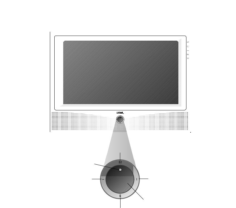
Control units Xelos A 26 and Xelos A 42
|
|
|
|
|
|
|
|
|
|
|
|
|
|
|
|
Display: |
Call the menu, |
||
|
in the menu: up5 |
|||
|
red = standby |
|||
|
|
|
|
|
|
green = operation |
|
|
|
orange = operation without screen display |
|
|
|
|
(radio mode, EPG data capture |
|
|
|
|
|
or timer recording) |
|
|
|
Station down, in the menu: left3
(1 Radio only for DVB reception, provided the station broadcasts this. Otherwise, switch over to an audio input.
Station up,
in the menu: right4
Switch TV set on/off to standby
Radio on/off (1 (back to TV mode), switching on the radio
from standby,
in the menu: down6
4

Control units Xelos A 32 and Xelos A 37
X E L O S
Display: red: standby green: operation green and red: timer recording, EPG data capture or radio mode
(1 Only for sets with DVB-T/C CI or can be retrofitted for sets with DVB-T/C.
Common Interface (1
Headphones connection
S-VHS connection (AVS)
(i.e. for camcorders) 

 Video input (AVS)
 Audio input right
Audio input left 
Call the menu, 
 in the menu: up/down56 –
Station down, + in the menu: left3
Station up, in the menu: right4
5
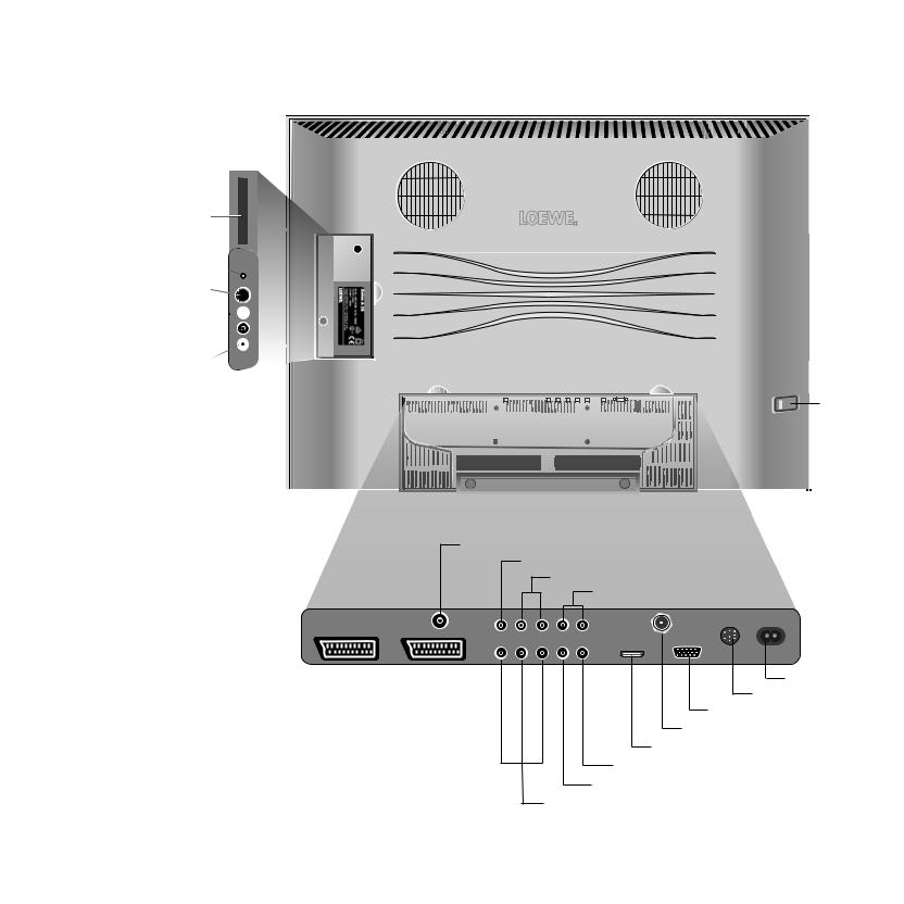
Connections to rear panel – Xelos A 26
Common interface
Headphone connection 
S-VHS connection (AVS)
(i.e. for camcorders) 


 Video input (AVS)

Audio input right 

Audio input left
Mains switch
Antenna/cable/analogue/digital
Center audio input (analogue)
Audio input left/right (analogue)
Audio output left/right (analogue)
|
|
|
|
Socket for |
|
|
|
|
|
power cable |
|
|
|
|
|
Service socket |
|
Euro-AV- |
Euro-AV- |
||||
VGA/XGA input |
|||||
socket1 |
socket2 |
||||
Satellite connection socket (1 |
|||||
|
|
|
|
||
|
|
|
|
HDMI (DVI) input |
|
|
|
|
|
Digital audio output |
|
|
|
|
|
Digital audio input |
|
|
|
|
|
Component video inputs (Cb/Pb–Cr/Pr–Y) |
|
(1 Digital satellite tuner can be retrofitted
6
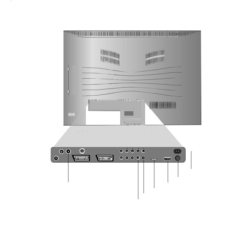
Connections to rear panel – Xelos A 32/37
Mains switch |
|
|
|
|
|
|
|
|
|
|
|
|
|
|
|
|
|
|
|
|
|
|
|
|
|
|
|
|
|
|
|
|
|
|
|
|
|
|
|
|
|
|
|
|
|
|
|
|
|
|
|
|
|
|
|
|
|
|
|
|
|
|
|
|
|
|
|
|
|
|
|
|
|
|
|
|
|
|
|
|
|
|
|
|
|
|
|
|
|
|
|
|
|
|
|
||
|
|
|
|
|
|
|
|
|
|
|
|
|
|
|
|
|
|
|
|
|
|
|
|
|
|
|
|
|
|
|
|
|
|
|
|
|
|
|
|
|
|
|
|
|
|
|
||
|
|
|
|
|
|
|
|
|
|
|
|
|
|
|
|
|
|
|
|
|
|
|
|
|
|
|
|
|
|
|
|
|
|
|
|
|
|
|
|
|
|
|
|
|
|
|
||
|
|
|
|
|
|
|
|
|
|
|
|
|
|
|
|
|
|
|
|
|
|
|
|
|
|
|
|
|
|
|
|
|
|
|
|
|
|
|
|
|
|
|
|
|
|
|
||
|
|
|
|
|
|
|
|
|
|
|
|
|
|
|
|
|
|
|
|
|
|
|
|
|
|
|
|
|
|
|
|
|
|
|
|
|
|
|
|
|
|
|
|
|
|
|
||
|
|
|
|
|
|
|
|
|
|
|
|
|
|
|
|
|
|
|
|
|
|
|
|
|
|
|
|
|
|
|
|
|
|
|
|
|
|
|
|
|
|
|
|
|
|
|
||
|
|
|
|
|
|
|
|
|
|
|
|
|
|
|
|
|
|
|
|
|
|
|
|
|
|
|
|
|
|
|
|
|
|
|
|
|
|
|
|
|
|
|
|
|
|
|
||
|
|
|
|
|
|
|
|
|
|
|
|
|
|
|
|
|
|
|
|
|
|
|
|
|
|
|
|
|
|
|
|
|
|
|
|
|
|
|
|
|
|
|
|
|
|
|
||
|
|
|
|
|
|
|
|
|
|
|
|
|
|
|
|
|
|
|
|
|
|
|
|
|
|
|
|
|
|
|
|
|
|
|
|
|
|
|
|
|
|
|
|
|
|
|
||
|
|
|
|
|
|
|
|
|
|
|
|
|
|
|
|
|
|
|
|
|
|
|
|
|
|
|
|
|
|
|
|
|
|
|
|
|
|
|
|
|
|
|
|
|
|
|
||
|
|
|
|
|
|
|
|
|
|
|
|
|
|
|
|
|
|
|
|
|
|
|
|
|
|
|
|
|
|
|
|
|
|
|
|
|
|
|
|
|
|
|
|
|
|
|
||
|
|
|
|
|
|
|
|
|
|
|
|
|
|
|
|
|
|
|
|
|
|
|
|
|
|
|
|
|
|
|
|
|
|
|
|
|
|
|
|
|
|
|
|
|
|
|
||
|
|
|
|
|
|
|
|
|
|
|
|
|
|
|
|
|
|
|
|
|
|
|
|
|
|
|
|
|
|
|
|
|
|
|
|
|
|
|
|
|
|
|
|
|
|
|
||
|
|
|
|
|
|
|
|
|
|
|
|
|
|
|
|
|
|
|
|
|
|
|
|
|
|
|
|
|
|
|
|
|
|
|
|
|
|
|
|
|
|
|
|
|
|
|
||
|
|
|
|
|
|
|
|
|
|
|
|
|
|
|
|
|
|
|
|
|
|
|
|
|
|
|
|
|
|
|
|
|
|
|
|
|
|
|
|
|
|
|
|
|
|
|
||
|
|
|
|
|
|
|
|
|
|
|
|
|
|
|
|
|
|
|
|
|
|
|
|
|
|
|
|
|
|
|
|
|
|
|
|
|
|
|
|
|
|
|
|
|
|
|
||
|
|
|
|
|
|
|
|
|
|
|
|
|
|
|
|
|
|
|
|
|
|
|
|
|
|
|
|
|
|
|
|
|
|
|
|
|
|
|
|
|
|
|
|
|
|
|||
|
|
|
|
|
|
|
|
|
|
|
|
|
|
|
|
|
|
|
|
|
|
|
|
|
|
|
|
|
|
|
|
|
|
|
|
|
|
|
|
|
|
|
|
|
|
|
|
|
|
|
|
|
|
|
|
|
|
|
|
|
|
|
|
|
|
|
|
|
|
|
|
|
|
|
|
|
|
|
|
|
|
|
|
|
|
|
|||||||||||
|
|
|
|
|
|
|
|
|
|
|
|
|
|
|
|
|
|
|
|
|
|
|
|
|
|
|
|
|
|
|
|
|
|
|
|
|
|
|
|
|
|
|
|
|
|
|
|
|
|
|
|
|
|
|
|
|
|
|
|
|
|
|
|
|
|
|
|
|
|
|
|
|
|
|
|
|
|
|
|
|
|
|
|
|
|
|
|
|
|
|
|
|
|
|
|
|
|
|
|
|
|
|
|
|
|
|
|
|
|
|
|
|
|
|
|
|
|
|
|
|
|
|
|
|
|
|
|
|
|
|
|
|
|
|
|
|
|
|
|
|
|
|
|
|
|
|
|
|
|
|
|
|
|
|
|
|
|
|
|
|
|
|
|
|
|
|
|
|
|
|
|
|
|
|
|
|
|
|
|
|
|
|
|
|
|
|
|
|
|
|
|
|
|
|
|
Antenna/cable PIP tuner(1 |
|
|
|
|
|
|
|
|
|
|
|
|
|
|
|
|
|
|
|
|
|
Center Audio input (analogue) |
|
|
|
|||||||||||||||||||||||
|
|
|
|
|
|
|
|
|
|
|
|
|
|
|
|
|
|
|
|
|
|
|
|
|||||||||||||||||||||||||
|
|
|
|
|
|
|
|
|
|
|
|
|
|
|
|
|
|
|
|
|
|
|
Audio input left/right (analogue) |
|
|
|
||||||||||||||||||||||
or satellite antenna |
Satellite antenna |
|
|
|
|
|
|
|
|
|
|
|
|
|
|
|
|
|
|
|||||||||||||||||||||||||||||
|
|
|
|
|
|
|
|
|
|
|
|
|
|
|
|
|
|
|||||||||||||||||||||||||||||||
(Sat tuner 1)(2 |
(Sat tuner 2)(3 |
|
|
|
|
|
|
|
|
|
|
|
|
|
|
|
|
|
Audio output left/right (analogue) |
|
|
|
||||||||||||||||||||||||||
|
|
|
|
|
|
|
|
|
|
|
|
|
|
|
|
|
|
|
|
|||||||||||||||||||||||||||||
|
|
|
|
|
|
|
|
|
|
|
|
|
|
|
|
|
|
|
|
|
|
|
|
|
|
|
|
|
|
|
|
|
|
|
|
|
|
|
|
|
|
|
|
|
|
|
|
|
|
|
|
|
|
|
|
|
|
|
|
|
|
|
|
|
|
|
|
|
|
|
|
|
|
|
|
|
|
|
|
|
|
|
|
|
|
|
|
|
|
|
|
|
|
|
|
|
|
|
|
|
|
|
|
|
|
|
|
|
|
|
|
|
|
|
|
|
|
|
|
|
|
|
|
|
|
|
|
|
|
|
|
|
|
|
|
|
|
|
|
|
|
|
|
|
|
|
|
|
|
|
|
|
|
|
|
|
|
|
|
|
|
|
|
|
|
|
|
|
|
|
|
|
|
|
|
|
|
|
|
|
|
|
|
|
|
|
|
|
|
|
|
|
|
|
|
|
|
|
|
|
|
|
|
|
|
|
|
|
|
|
|
|
|
|
|
|
|
|
|
|
|
|
|
|
|
|
|
|
|
|
|
|
|
|
|
|
|
|
|
|
|
|
|
|
Antenna/cable |
Euro-AV- |
Euro-AV- |
Component |
|
|
|
|
|
|
|
|
|
Socket for power |
analogue/digital |
socket 1 |
socket 2 |
video inputs |
|
|
|
|
|
|
|
|
|
cable |
(tuner 1) |
|
|
(Cb/Pb–Cr/Pr–Y) |
|
|
|
|
|
|
|
|
|
Service socket |
|
|
|
|
|
|
|
|
|
|
|
|||
Antenna output PIP tuner(1 |
|
|
|
|
|
|
|
|
|
VGA/XGA input |
|||
|
|
|
|
|
|
|
|
|
|||||
connect to tuner 1 |
|
|
|
|
|
|
|
HDMI (DVI) input |
|||||
|
|
|
|
|
|
|
|||||||
|
|
|
|
|
|
|
Digital audio output |
||||||
|
|
|
|
|
|
|
|||||||
|
|
|
|
|
Digital audio input |
||||||||
|
|
|
|
|
|||||||||
(1
(2
(3
Can be retrofitted. This is already integrated in sets with a digital recorder. Digital satellite tuner can be retrofitted.
Can be retrofitted for sets with a digital recorder.
7
Connections to rear panel – Xelos A 42
Common interface
89352.001 |
ANT -SAT |
|
|
|
13/18 V |
/350 mA |
|
|
ANT -TV |
AV 1 |
AV 2 |
5 V |
/80 mA |
|
( RGB / YUV ) |
|
AUDIO IN |
|
AUDIO OUT |
|
|
|
|
|
|
|
|
|
|
|
|
|
|||
|
|
|
|
|
|
|
|||
|
|
|
|
|
|
|
|||
|
|
|
|
|
|
|
|||
C |
L |
R |
L |
R |
HDTV IN |
SERVICE |
|
||
SD/HD-COMPONENT IN |
AUDIO DIGI |
TA L |
|
|
|
|
|||
Cb/Pb |
Cr/Pr |
Y |
IN |
OUT |
HDMI (DVI ) |
VGA/XGA |
|
||
 Audio input left
 Audio input right
 Video input (AVS)

 S-VHS input (AVS) (i.e. for camcorders)
Headphone connection
Mains switch
Power cable |
|
|
|
|
|
|
|
|
|
|
|
|
|||
|
|
|
|
|
|
|
|
Antenna/cable PIP tuner (1 |
Satellite antenna |
||||||
or satellite antenna |
|||||||
|
(Sat tuner 1) (2 |
(Sat tuner 2) (3 |
|||||
Center Audio input (analogue) Audio input left/right (analogue)
Audio output left/right (analogue)
|
|
|
|
|
|
|
|
|
|
|
|
|
|
|
|
|
|
|
|
|
|
|
|
|
|
|
|
|
|
|
|
|
|
|
|
|
|
|
|
|
|
|
|
|
|
|
|
|
|
|
|
|
|
|
|
|
|
|
|
Antenna/cable |
Euro-AV- |
Euro-AV- |
|
|
|
|
|
|
|
|
|
|
|
|
|
Service socket |
|||
|
|
|
|
|
|
|
|
|
|
|
|
||||||||
analogue/digital |
socket 1 |
socket 2 |
|
|
|
|
|
|
|
|
|
|
|
VGA/XGA input |
|||||
(tuner 1) |
|
|
|
|
|
|
|
|
|
|
|
|
|
|
|
||||
|
|
|
|
|
|
|
|
|
|
|
|
|
|
|
|||||
|
|
|
|
|
|
|
|
|
|
|
|
|
|
|
|
|
|
||
Antenna output PIP tuner (1 |
|
|
|
|
|
|
|
|
|
|
|
HDMI (DVI) input |
|||||||
|
|
|
|
|
|
|
|
|
|
|
|||||||||
|
connect to tuner 1 |
|
|
|
|
|
|
|
|
|
Digital audio output |
||||||||
|
|
|
|
|
|
|
|
|
|||||||||||
|
|
|
|
|
|
|
|
|
|
|
Digital audio input |
||||||||
|
|
|
|
|
|
|
|
|
|
|
|||||||||
|
|
|
|
|
|
|
|
Component video inputs (Cb/Pb–Cr/Pr–Y) |
|||||||||||
|
|
|
|
|
|
|
|
||||||||||||
(1
(2
(3
Can be retrofitted. This is already integrated in sets with a digital recorder. Digital satellite tuner can be retrofitted.
Can be retrofitted for sets with a digital recorder.
8

Welcome
Thank you!
At Loewe, we combine the highest standards of technology, design and user friendliness. This applies equally for TV, video and accessories. Your new TV set is ideally equipped for the TV standard of the future - ”HDTV” (High Definition Television). With its high-resolution screen and
the future-proof digital interfaces HDMI, you have the option to view HD content with excellent picture quality. It therefore carries the European quality mark “HD ready”.
Digital TV is steadily spreading via terrestrial reception, in the cable network and via satellite. Loewe supplies sets equipped with DVB-T and DVB-C (DVB-C not for UK). A digital satellite tuner (DVB-S) can be retrofitted. The DVB integrated within the TV set is operated via the TV set menus using the remote control.
We have designed this TV set so that it is easy to operate by using menus. Information about settings in menus is shown automatically; this enables you to understand the context quickly.
You will find the answers to many of your technical queries in the index of your TV. If you want to operate the TV, you can access functions directly from the index. This saves you from having to read through detailed operating instructions and is the reason why this operating manual only explains the most important operating steps.
TV equipment
The maximum equipment is described in these operating instructions (without optional retrofit kits). Functions indicated by are not available in all TV sets. Menu contents may differ from the ones shown, depending on how your TV is equipped.
You can display how your set is equipped in the “Integrated features“ index (press the INFO button in the TV mode if no menu is displayed; the “Integrated features“ menu item is also displayed in the index before the initial letter A).
There are separate operating instructions for Digital Recorder Plus with the additional DVB satellite tuner.
Scope of delivery
•LCD-TFT TV or Plasma TV set
•RC4 remote control with 2 batteries
•Table stand
•Marketing and service card
•Fabric hose for Xelos A32/37/42
•3 cable loops for Xelos A42
•These operating instructions
Transporting
Only transport the unit in an upright position. Hold the set by the top and bottom edges of the housing. The plasma/LCD screen is made of glass and/or plastic and may break if not handled carefully. Should the LCD screen become damaged or should the liquid crystal begin to leak, then it is imperative you wear rubber gloves when removing the set. Should the liquid come in contact with your skin, thoroughly rinse with water immediately.
Installation options
As a desktop unit
Use the stand included in delivery. There are assembly instructions included with the stand. First read these assembly instructions and then set up your set.
As a wall-mounted unit
Use the wall holder WM52 for Xelos A 26, Loewe order no. 63493A00. Use the wall holder WM53 for Xelos A 32/37, Loewe order no. 63493A10. Use the wall holder WM61 for Xelos A 42, Loewe order no. 64495L00.
As unit mounted on a rack for Xelos A 32/37
Use the Xelos Rack, Loewe order no. 64496.A00.
Or use the Flat-TV F-Stand 3, Loewe order no. 64498.A00.
As a rotating, free-standing unit mounted on a rack for Xelos A 32/37/42
Use the Xelos 42 Rack, Loewe order no. 64496.A01.
Note on the LCD screen
The TV set with an LCD screen you have purchased meets the highest quality requirements and has been tested for pixel errors. Despite the utmost caution in production of the displays, it cannot be totally ruled out that some of the pixels might be defective for technological reasons. Please understand that such effects cannot be considered a unit defect as defined by the warranty as long as they are within the limits specified by the standard.
9

Welcome
Note on the plasma screen (Xelos A 42)
The TV set with plasma screen you have purchased meets the highest quality requirements and has been tested for pixel errors. Despite the utmost caution in production of the displays, it cannot be totally ruled out that some of the pixels might be defective for technological reasons. Please understand that such effects cannot be considered a unit defect as defined by the warranty as long as they are within the limits specified.
For plasma screens, the emission of light decreases the longer the unit is used.
Plasma screens work by using phosphor. In certain operating conditions, this technology may facilitate image burns. These operating conditions include:
•Lengthy, continuous display of a freeze frame (>10 minutes).
•Constant display of the same background.
•Use of a format that does not entirely fill the screen (such as 4:3) for a longer period of time.
Once an image is burnt into the display, it is usually not possible to remedy the problem; this situation is neither covered by the warranty nor by the guarantee. To avoid or reduce image burns on your screen, please follow these instructions and recommendations:
•During the first 100 hours of operation, you should display moving pictures for the most part or freeze frames that change frequently; these images are to fill the entire screen.
•Use your screen in a full screen format (16:9).
•If you use the screen as a PC monitor, always activate the screen saver.
•Always switch off the TV set when not in use.
•Reduce contrast and brightness as much as possible.
The “DRM” function (Digital Refresh Mode), which can be called in this set, may be able to eliminate or reduce minor visible effects.
Any effects resulting from an excessively long display of a freeze frame cannot be reversed using the “DRM” function.
Cleaning
Use only a soft, clean, damp cloth to clean the TV set, the screen and remote control (do not use any caustic or abrasive cleaning agents).
Disposal
Packing and box
You have chosen a long lasting technical product of very high quality. We have paid a fee to authorised recyclers who will collect the packing from your dealer for disposal, pursuant to domestic regulations. Nevertheless, we recommend you to keep the original box and packing material for optimum protection if you have to transport the set.
The set
Attention: The EU directive 2002/96/EC regulates the proper way to recycle, handle and utilise used electronic
devices. Hence, all used electronic devices are to be disposed of separately. Please do not dispose of this set in the normal household rubbish.
You may return your used set free of charge at designated recycling centres or at your specialist
dealer whenever you purchase a new, comparable set. You can find out more about recycling (also for countries outside the EU) from your local government.
10
For your safety
For your safety and to avoid unnecessary damage to your TV set, please read and observe the following safety instructions:
•This TV set is designed exclusively for reception and reproduction of video and audio signals.
• This equipment is designed for domestic and |
|
office environments and must not be used in |
|
rooms with high humidity |
|
(e.g. bathroom, sauna) or |
|
high concentrations of dust |
|
(e.g. workshops). If the |
|
equipment is used in the |
|
open air, ensure that it is |
|
protected against moisture |
|
(rain, drips, splashes, |
|
sprayed water or dew). Do |
. |
not place any containers |
|
filled with liquids or lit |
|
candles on top of the TV. |
|
High levels of moisture and |
|
concentrations of dust cause leakage currents in the equipment, which can lead to danger of electric shock or fire.
The manufacturer‘s warranty is only valid for use in the specified permissible environment.
•If you have moved the TV set out of the cold into a warm environment, leave it standing for about an hour since condensation may form.
•This equipment must
only be connected to
a mains power supply |
10 cm |
||||||||||||||
|
|
|
|
|
|
|
|
||||||||
which has the same |
|
|
|
|
|
|
|
|
|
|
|
|
|
|
|
|
|
|
|
|
|
|
|
|
|
|
|
|
|
|
|
voltage and frequency |
|
|
|
|
|
|
|
|
|
|
|
|
|
|
|
as that specified on the 10 |
cm |
|
|
|
|
|
|
|
|
|
|
|
|
10 |
cm |
rating plate; use the |
|
|
|
|
|
|
|
|
|
|
|
|
|
|
|
power cable provided. |
|
|
|
|
|
|
|
|
|
|
|
|
|
|
|
Incorrect voltages |
|
|
|
|
|
|
|
|
|
|
|
|
|
|
|
can damage the |
|
|
|
|
|
|
|
. |
|
|
|
|
|
|
|
|
|
|
|
|
|
|
|
|
|
|
|
|
|
|
|
equipment. |
|
|
|
|
|
|
|
|
|
|
|
|
|
|
|
|
|
|
|
|
|
|
|
|
|
|
|
|
|
|
|
|
|
|
|
|
|
|
|
|
|
|
|
|
|
|
|
|
|
|
|
|
|
|
|
|
|
|
|
|
|
|
|
•Like all electronic equipment, your TV
needs air for cooling. Obstruction of the air circulation can cause fires. Therefore the air vents on the back must always be kept free. Please do not place newspapers or cloths on/over the TV. If the TV is placed in a cabinet or on a shelf, leave at least 10 cm at the sides and 10 cm at the top to ensure sufficient air circulation.
Position the set so that it is not exposed to direct sunlight and additional heating from radiators.
•Prevent any metal parts, needles, paper clips, liquids, wax or the like from getting into the TV set through the air venting slits in the rear panel. This can lead to short-circuits and possibly to fire. If something should get into the inside of the TV set, pull out the plug immediately and notify customer service.
•Never remove the back of the TV set yourself. Repair and servicing of your TV set should only be carried out by authorised TV technicians.
•Place the TV set on a level, firm base. The set should not protrude at the front when installing in cabinets or shelves.
Only use original accessories if possible, e.g. Loewe wall holders and stands.
Never let children handle the TV unattended.
Do not allow children to play in the immediate vicinity of the TV, they could knock, shift or pull it over and injure someone.
Never leave the TV on unsupervised.
•Do not install the TV where there may be vibrations. Vibrations can lead to material stress.
•Pull out the power and antenna cables during thunderstorms. Surge voltages caused by lightning strikes can damage the TV through the antenna system and the mains. Also remove the antenna and mains plugs in long periods of absence.
•The mains plug of the TV set must be easily accessible so that the set can be disconnected at any time.
•Lay the mains cable in such a way that it will not be damaged. The power cable may not be kinked or laid over sharp edges, not stood on and not exposed to chemicals, the latter also applies to the device as a whole. A mains cable with damaged insulation can lead to electric shocks and is a fire risk.
•When removing the mains plug, pull the plug housing and not the cable. The wires in the plug could be damaged and cause a short circuit the next time it is plugged in.
11
First installation
Remote control
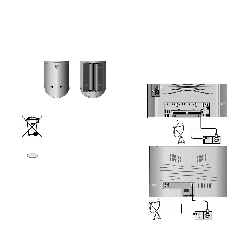
Batteries
To insert or change the batteries, press on the arrow. Slide the battery compartment cover downwards and remove it. Insert LR 03 alkalinemanganese batteries (AAA) and ensure that the + and - ends are positioned correctly.
 +
+
+
Then push the cover back on from the bottom.
Note on disposing batteries:
The batteries provided contain no harmful materials such as cadmium, lead or mercury.
Regulations concerning used batteries stipulate that batteries may no longer be thrown out with the household rubbish. Deposit any used batteries free of charge into the designated collection containers set up at commercial businesses.
Setting up the remote control for operating the TV
TV Push the TV button.
How to operate other Loewe equipment is described on page 39.
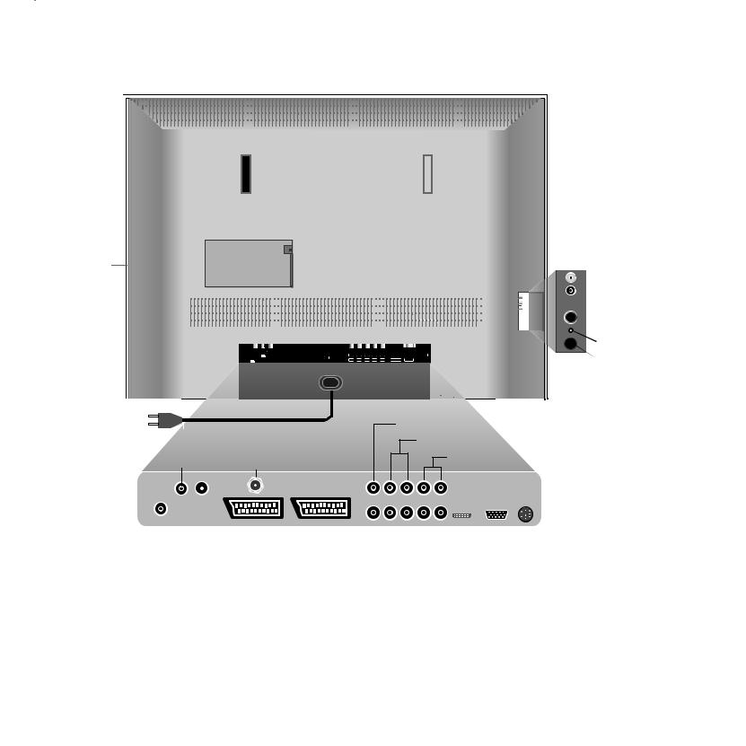
Connection
Power mains
Remove the cover for the connections.
Connect the TV set to a 220-240V/50- 60 hertz power outlet. For Xelos A 26/32/37, plug the small plug of the mains cable into the mains socket on the rear of the TV set; plug the large mains plug into a mains socket.
Antennas
Plug the antenna plug of your antenna/cable system or the room antenna for DVB-T into the ANT-TV socket (Tuner 1 for Xelos A 32/37/42).
|
|
220-240V~ |
ANT-TV |
ANT-SAT |
50/60Hz |
Xelos A 26
|
220-240V~ |
ANT-TV ANT-SAT |
50/60Hz? |
Xelos
A 32/37/42
TV |
R |
12
First installation
If the reception conditions are good, then a room antenna may be used for DVB-T. Passive and active room antennas are available on the market. The power is supplied for an active antenna via the antenna connection. For automatic programming or in “TV Menu – Connections – Antenna DVB – Antenna DVB-T,“ the distribution voltage (5 volts) is to be set correspondingly.
It may be practical to use a nondirectional antenna. If the location is outside the normal transmitting range, then a unidirectional antenna may also be used to improve the reception quality.
You can find out more on the digital stations that can be received in your area at your specialist dealer.
If a Xelos A32/37/42 was retrofitted with a PIP tuner or if this is already integrated in a set with a digital recorder, then plug the antenna into the antenna input of the PIP tuner and connect the PIP tuner output with the ANT-TV socket (Tuner 1). See illustrations on page 7/8.
If a Digital Satellite Tuner 1 has been retrofitted, connect your satellite antenna system to the ANT-SAT socket.
If a Digital Satellite Tuner 2 has been retrofitted (only in conjunction with the Digital Recorder+), then connect one antenna cable each, for example from the antenna switch or from the twin LNC, to both SAT sockets.
When laying the cable, use the cable clips affixed beneath the TV set. Replace the connection cover on the TV set.
Handling the fabric hose
Use the fabric hose included with Xelos A 32/37/42 to lay the mains cables, antenna cables or cables from other electronic components systematically; then lead the
hose with the cables to the connection boxes. This provides you with an elegant solution when laying cables.
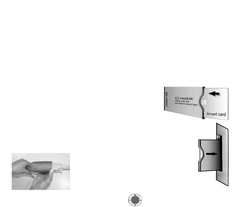
The diameter of the fabric hose increases when you push it together lengthwise (see illustration). This makes it easier for you to push through cables with plugs.
Using the common interface module
(only for sets with CI slot)
In order to be able to receive encrypted digital stations, the common interface module (CI module) and the smartcard both have to be inserted into the corresponding slot of your TV set. You can purchase the CI module and smartcard at your specialist dealer. You can find the slot on the back of your TV set, see the illustrations on pages 6 – 8.
1.Make sure the TV set is switched off with the mains switch on the set, or pull the mains plugs.
2.First push the smartcard into the CI module as far as it will go. Insert it so that the side with the golden contact chip faces the side of the module printed with
the supplier‘s brand logo. Printed arrows indicate how to insert the card. Also follow the installation instructions included with the smartcard.
3.Slide the CI module carefully into the slot with the contact side facing the front. The logo on the
common interface module should be visible. |
Eject button |
|
Make sure the module is not twisted in the |
|
|
|
|
|
process. Do not use force. |
|
INTERFACE |
pressed outwards. |
|
|
When the module locks, the eject button is |
|
|
The CI module and the smartcard are not included |
CI module |
COMMON |
|
||
in the scope of delivery for this set; you can usually |
|
|
|
|
|
obtain them at your specialist dealer. |
|
|
Switching on
Press the mains switch (for Xelos A 32/37, the set switches on immediately, the green indicator lamp lights up).
|
For Xelos A 26/42: |
|
) |
The red indicator on the set now lights up (standby mode). |
|
Switch on the set using the switch integrated in the |
||
|
||
|
indicator. |
After switching on, it takes about 2 minutes for the screen to reach full brightness due to the LCD technology.
13
First installation
Automatic programming
Automatic programming of the TV set is started the first time you switch it on. Follow the menus.
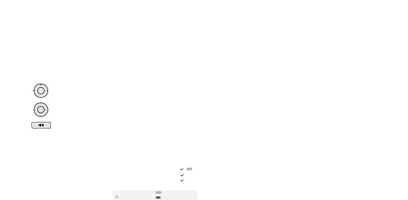
By tilting the OK button in one of the arrow directions, you
OK
can choose the settings ...
... and confirm your settings by pressing OK. You then go
OK
to the next menu.
Back to the previous menu.
1.First you have to select the menu language.
2.By pressing the OK button, you can call the menu “Connect antenna(s) for“. If you want to receive digital stations via satellite, then choose
“Satellite DVB-S“ - confirm using |
|
|
|
|
|
|
|
First installation wizard |
|
|
|
|
|
||
the yellow colour button. If |
Connect antenna(s) for |
|
|
|
|
|
|
|
|
|
|
|
|
||
you also want to receive digital |
|
Antenna/cable (analogue)(to ANT TV) |
|
33 |
|||
|
Antenna DVB-T |
(to ANT TV) |
|
|
|||
terrestrial stations (DVB-T), |
|
|
|
||||
|
Antenna DVB-C |
(to ANT TV) |
|
|
|||
then select “Antenna DVB-T“. |
|
Satellite DVB-S |
(at ANT SAT) |
|
|
||
|
|
|
|
|
|
|
|
Also select “Antenna/cable |
OK Proceed |
|
|
Connect |
|
|
|
|
|
|
|
||||
|
|
Back |
|
|
|||
(analogue)“ - this way the standard
analogue stations can also be searched for and saved. If you can receive digital stations from the cable network, then select “Antenna DVB-C“ using the yellow colour button.
3.For the country-specific station sorting, enter the location.
4.If you have selected “DVB-T“, you then reach the menu “Antenna DVB- T“. If you use an active antenna, then select “yes (5V)“.
5.In the “Select satellite installation“ menu, make the selection that corresponds to your satellite antenna installation.
Note: If you have any questions on how your satellite antenna installation is configured and on the antenna settings, consult your antenna installer or your specialist dealer.
6.Select the satellite the antenna is directed at, such as ASTRA1. If you only receive one satellite...
7.In the following menu, specify whether the station search should take place in the high and low band (“Yes“) or only in the low band (“No“). Note: For most satellites, a station search is required in both bands.
8.For the low band and high band, the standard frequencies 9750 MHz (9.75 GHz) and 10600 MHz (10.6 GHz) are preset.
If your satellite antenna is equipped with an LNC (LNB) with a divergent oscillator frequency, specify the corresponding frequency for low and
high band respectively. Note: The correct display of the received frequencies in the “TV menu – Stations – Manual adjustment“ depends upon this setting.
9.You should receive a picture with sound with the settings previously made (only for ASTRA 1 and HOTBIRD). Then press OK.
10.In the “Pre-programming“ menu, select the factory-set preprogramming to programme the satellite stations quickly.
To ensure all stations that can be currently received are searched for and saved, select “No“ at this point.
Symbol rates: The standard symbol rates 22000 and 27500 are preset. If you would like to receive stations with different symbol rates, specify the corresponding values here using the numeric buttons on your
remote control.
11.Press OK to obtain an overview of the settings with which the automatic programming is to take place.
12.Press the OK button again and the station search will start. The TV set searches for, sorts and saves all the TV stations that can be received, according to your settings and the antennas connected.
13.When the TV stations are saved, you will receive a corresponding message.
14.Press the OK button and the set then searches for the radio stations.
15.The TV set searches for, saves and sorts all radio stations which can be received with your antenna system.
16.Then log on your video equipment, decoder and audio system using the connection wizard and connect these to the TV according to the connection diagram displayed. If you want to connect other equipment later, you can find information as of page 32.
You can repeat the initial installation at any time, e.g. after moving house. Call the index using the INFO button (in the TV mode, if no menu is opened). Select the index item “Repeat initial installation“ (you will find this listed separately before the letter A). Press OK to start the initial installation.
Note: For DVB-T stations in UK the stations are tied to “Logical Channel Numbers” – “LCN” and sorted from 1–799. Digital station without “LCN” are stored from 800 onwards. Analogue stations are stored from1001.
Station sorting
Note: not with DVB-T stations in UK.
You can change the station sorting that was carried out automatically later at any time, see “TV menu –Settings– Stations– Change stations“.
14
 Loading...