


Kight XL 400-801
OKBX-I-O Rev B
Outdoor Knight XL
Installation & Operation Manual
Models: 400 - 801
WARNING
Save this manual for future reference.
This manual must only be used by
a qualifi ed heating installer / service
technician. Read all instructions,
including this manual and the
Outdoor Knight XL Service Manual,
before installing. Perform steps in
the order given. Failure to comply
could result in severe personal
injury, death, or substantial property
damage.
Contents
HAZARD DEFINITIONS .................................................... 2
PLEASE READ BEFORE PROCEEDING ........................ 3
THE OUTDOOR KNIGHT XL -- HOW IT WORKS......... 4-6
RATINGS ........................................................................... 7
1. DETERMINE BOILER LOCATION
Flooring and Foundation .................................................... 9
Prevent Combustion Air Contamination ............................. 9
Corrosive Contaminants and Sources ................................9
2. PREPARE BOILER
Remove Boiler from Wood Pallet ..................................... 10
Install Flue Pipe Assembly .......................................... 10-11
Gas Conversions .............................................................. 12
Model 400 ....................................................................12
Model 501 ................................................................... 13
Models 601 - 801 ........................................................ 13
Leveling the Boiler ............................................................ 13
3. HYDRONIC PIPING
System Water Piping Methods ..........................................14
Low Water Cutoff Device ................................................. 14
Chilled Water System ........................................................14
Freeze Protection ............................................................. 14
General Piping Information ............................................... 14
Flow Switch and Relief Valve Installation ....................... 15
Flow Switch Adjustment...............................................16
Circulator Sizing ............................................................... 17
4. GAS CONNECTIONS
Connecting Gas Supply Piping .........................................24
Natural Gas ...................................................................... 25
Pipe Sizing for Natural Gas .........................................25
Natural Gas Supply Pressure Requirements ............. 25
Propane Gas .....................................................................25
Pipe Sizing for Propane Gas ...................................... 25
Propane Supply Pressure Requirements ................... 25
Check Inlet Gas Supply ................................................... 26
Gas Pressure ................................................................... 27
Gas Valve Replacement ................................................... 27
5. FIELD WIRING
Line Voltage Connections .................................................28
Low Voltage Connections ............................................28-29
Wiring of the Cascade ...................................................... 30
6. CONDENSATE DISPOSAL
Condensate Drain ............................................................ 32
7. STARTUP .............................................................. 33-38
8. OPERATING INFORMATION
General ............................................................................. 39
Cascade ............................................................................42
Sequence of Operation ............................................... 43-44
Outdoor Knight XL Control Module .................................. 45
Status Display Screens ............................................... 46-48
9. MAINTENANCE
Maintenance and Annual Startup .................................49-53
10. DIAGRAMS
Wiring Diagram ........................................................... 54
Ladder Diagram ...........................................................55
Revision Notes .................................................. Back Cover
Hazard defi nitions
The following defi ned terms are used throughout this manual to bring attention to the presence of hazards of various risk levels
or to important information concerning the life of the product.
DANGER
WARNING
CAUTION
CAUTION
NOTICE
DANGER indicates an imminently hazardous situation which, if not avoided, will result in death or serious
injury.
WARNING indicates a potentially hazardous situation which, if not avoided, could result in death or serious
injury.
CAUTION indicates a potentially hazardous situation which, if not avoided, may result in minor or moderate
injury.
CAUTION used without the safety alert symbol indicates a potentially hazardous situation which, if not
avoided, may result in property damage.
NOTICE indicates special instructions on installation, operation, or maintenance that are important but not
related to personal injury or property damage.
2
Please read before proceeding
WARNING
Installer – Read all instructions, including
this manual and the Outdoor Knight XL
Service Manual, before installing. Perform
steps in the order given.
When servicing boiler –
• To avoid electric shock, disconnect electrical supply
before performing maintenance.
Outdoor Knight XL Installation & Operation Manual
NOTICE
WARNING
WARNING
User – This manual is for use only by
a qualified heating installer/service
technician. Refer to the User’s Information
Manual for your reference.
Have this boiler serviced/inspected by
a qualifi ed service technician, at least
annually.
Failure to comply with the above could
result in severe personal injury, death or
substantial property damage.
When calling or writing about the boiler
– Please have the boiler model and serial
number from the boiler rating plate.
Consider piping and installation when
determining boiler location.
Any claims for damage or shortage in
shipment must be fi led immediately
against the transportation company by the
consignee.
Factory warranty (shipped with unit) does
not apply to units improperly installed or
improperly operated.
Failure to adhere to the guidelines on this
page can result in severe personal injury,
death, or substantial property damage.
If the information in this manual is not
followed exactly, a fi re or explosion may
result causing property damage, personal
injury or loss of life.
This appliance MUST NOT be installed in
any location where gasoline or fl ammable
vapors are likely to be present.
WHAT TO DO IF YOU SMELL GAS
• Do not try to light any appliance.
• Do not touch any electric switch; do
not use any phone in your building.
• Immediately call your gas supplier
from a near by phone. Follow the
gas supplier’s instructions.
• If you cannot reach your gas supplier,
call the fi re department.
• Installation and service must be
performed by a qualifi ed installer,
service agency, or the gas supplier.
• To avoid severe burns, allow boiler to cool before
performing maintenance.
Boiler operation –
• Do not block fl ow of combustion or ventilation air to
the boiler.
• Should overheating occur or gas supply fail to shut off,
do not turn off or disconnect electrical supply to
circulator. Instead, shut off the gas supply at a location
external to the appliance.
• Do not use this boiler if any part has been under water.
The possible damage to a fl ooded appliance can be
extensive and present numerous safety hazards. Any
appliance that has been under water must be replaced.
Boiler water –
• Thoroughly fl ush the system (without boiler connected)
to remove sediment. The high-effi ciency heat exchanger
can be damaged by build-up or corrosion due to sediment.
• Continual fresh make-up water will reduce boiler life.
Mineral buildup in the heat exchanger reduces heat
transfer, overheats the stainless steel heat exchanger,
and causes failure. Addition of oxygen carried in by
makeup water can cause internal corrosion in system
components. Leaks in boiler or piping must be repaired
at once to prevent makeup water.
CAUTION
CAUTION
Do not use petroleum-based cleaning or
sealing compounds in the boiler system.
Gaskets and seals in the system may be
damaged. This can result in substantial
property damage.
Do not use “homemade cures” or “boiler
patent medicines”. Serious damage to the
boiler, personnel, and/or property may
result.
Freeze protection fl uids –
• NEVER use automotive antifreeze. Use only inhibited
propylene glycol solutions, which are specifi cally
formulated for hydronic systems. Ethylene glycol is
toxic and can attack gaskets and seals used in hydronic
systems.
3

The Outdoor Knight XL - How it works...
Outdoor Knight XL Installation & Operation Manual
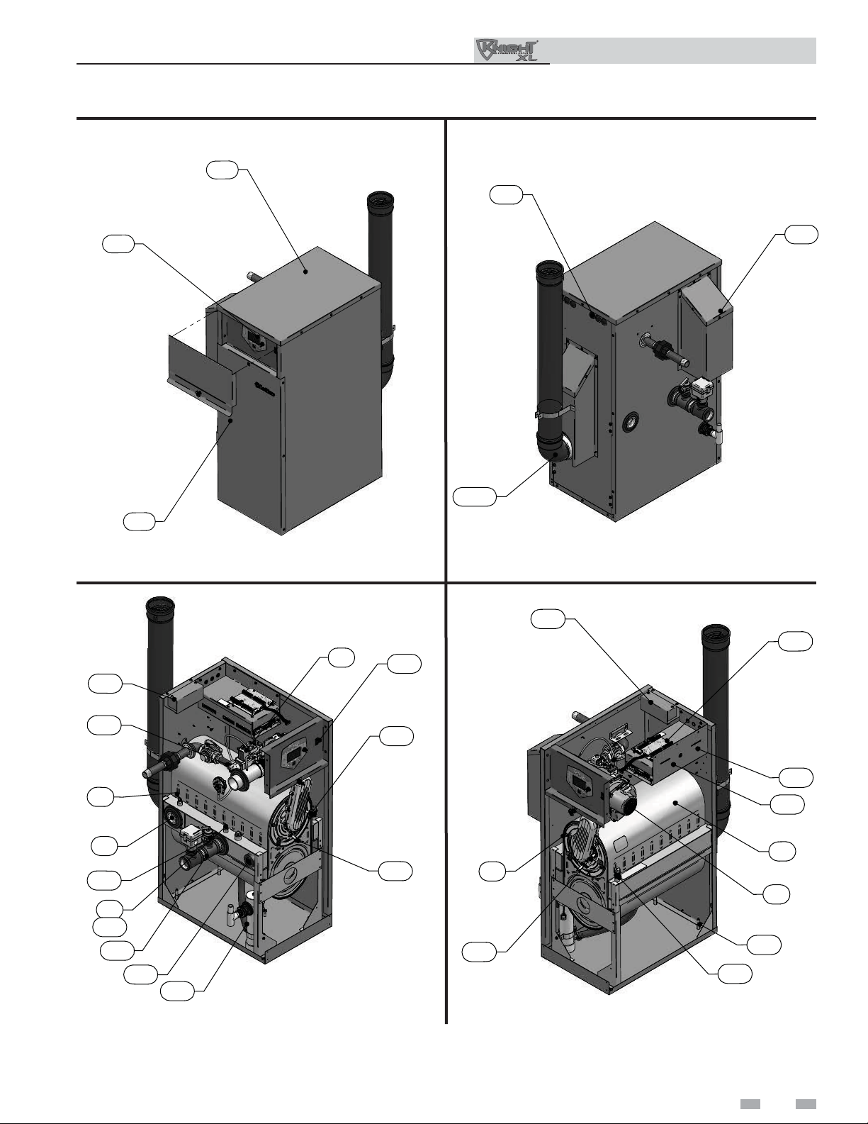
1. Stainless steel heat exchanger
Allows system water to fl ow through specially designed
coils for maximum heat transfer, while providing protection
against fl ue gas corrosion. The coils are encased in a jacket that
contains the combustion process.
2. Combustion chamber access cover
Allows access to the combustion side of the heat exchanger
coils.
3. Blower
The blower pulls in air and gas through the venturi (item 5).
Air and gas mix inside the blower and are pushed into the
burner, where they burn inside the combustion chamber.
4. Gas valve
The gas valve senses the negative pressure created by the
blower, allowing gas to fl ow only if the gas valve is powered and
combustion air is fl owing.
5. Venturi
The venturi controls air and gas fl ow into the burner.
6. Flue gas sensor (limit rated - not shown)
This sensor monitors the fl ue gas exit temperature. The
control module will modulate and shut down the boiler if the
fl ue gas temperature gets too hot. This protects the fl ue pipe from
overheating.
7. Boiler outlet temperature sensor (housed with the
high limit sensor)
This sensor monitors boiler outlet water temperature (system
supply). If selected as the controlling sensor, the control
module adjusts boiler fi ring rate so the outlet temperature is
correct.
8. Boiler inlet temperature sensor
This sensor monitors return water temperature (system
return). If selected as the controlling sensor, the control
module adjusts the boiler fi ring rate so the inlet temperature is
correct.
9. Temperature and pressure gauge (fi eld installed, not
shown)
Monitors the outlet temperature of the boiler as well as the
system water pressure.
10. Electronic LCD display
The electronic display consists of 4 buttons, a navigation dial
and a multiple line liquid crystal display.
11. Flue pipe assembly
Factory-supplied components for complete venting
system.
12. Burner (not shown)
Made with metal fi ber and stainless steel construction, the
burner uses pre-mixed air and gas and provides a wide range of
fi ring rates.
13. Water outlet (system supply)
A 1-1/2" or 2" NPT (depending on the model) water
connection that supplies hot water to the system.
14. Water inlet (system return)
A 1-1/2" or 2" NPT (depending on the model) water connection
that returns water from the system to the heat exchanger.
15. Gas connection pipe
Threaded pipe connection of 1". This pipe should be connected
to the incoming gas supply for the purpose of delivering gas to
the boiler.
16. SMART SYSTEM Control Module
The SMART SYSTEM Control responds to internal and
external signals and controls the blower, gas valve, and pumps
to meet the heating demand.
17. Manual air vent
Designed to remove trapped air from the heat exchanger
coils.
18. Air intake
Provides combustion air to the appliance.
19. Air Intake Cover
Provides protection from outdoor elements.
20. High voltage junction box
The junction box contains the connection points for the line
voltage power and all pumps.
4
21. Boiler drain port
Location from which the heat exchanger can be drained.
22. Low voltage connection board
The connection board is used to connect external low voltage
devices.
23. Low voltage wiring connections (plugs)
Conduit connection points for the low voltage connection
board.
24. Condensate drain connection
Connects the condensate drain line to a 1/2” PVC union.
25. Access cover - front
Provides access to the gas train and the heat exchanger.
26. Ignition electrode
Provides direct spark for igniting the burner.
27. Flame inspection window
The quartz glass window provides a view of the burner surface
and fl ame.
28. Gas shutoff valve
Manual valve used to isolate the gas valve from the gas supply.
29. Relief valve
Protects the heat exchanger from an over pressure condition.
The relief valve provided with the unit is set at 50 PSI.
30. Flame sensor
Used by the control module to detect the presence of burner
fl ame.
31. Line voltage wiring connections (knockouts)
Conduit connection points for the high voltage junction box.
32. Top panel
Removable panel to gain access to the internal components.
33. Power switch
Turns 120 VAC ON/OFF to the boiler.
34. Leveling legs
Used to allow the heat exchanger to be leveled. This is needed
for the proper draining of the condensate from the combustion
chamber.
35. Air shroud (Model 501 only)
The air shroud controls air and gas fl ow into the burner.
36. Air pressure switch
The air pressure switch detects blocked fl ue/inlet conditions.
break the control circuit, shutting the boiler down.
37. Pump relay board
The pump relay board is used to connect the boiler, system and
DHW pumps.
38. Transformer (not shown)
The transformer provides 24V power to the integrated control.
39. High limit sensor (housed with the outlet temperature
sensor)
Device that monitors the outlet water temperature. If the
temperature exceeds its setting, the integrated control will break
the control circuit, shutting the boiler down.
40. Over-temp switch (located underneath vent cover not shown)
An electrical switch designed to shut down boiler operation in
the event the outer back of the heat exchanger, directly above the
fl ue connection exceeds 604°F (318°C). This is a one time
switch and could warrant a heat exchanger replacement. Check
the integrity of the rear refractory at the back of the upper coil if
the switch opens.
41. Vent Cover
Covers Over-temp switch and fl ue collar with fl ue sensor.
42. Flow switch
The fl ow switch is a safety device that ensures fl ow through
the heat exchanger during operation. This appliance is low
mass and should never be operated without fl ow. The fl ow
switch makes contact when fl ow is detected and allows the unit
to operate. If fl ow is discontinued during operation for any
reason the fl ow switch will break the control circuit and the
unit wll shut down.
Outdoor Knight XL Installation & Operation Manual
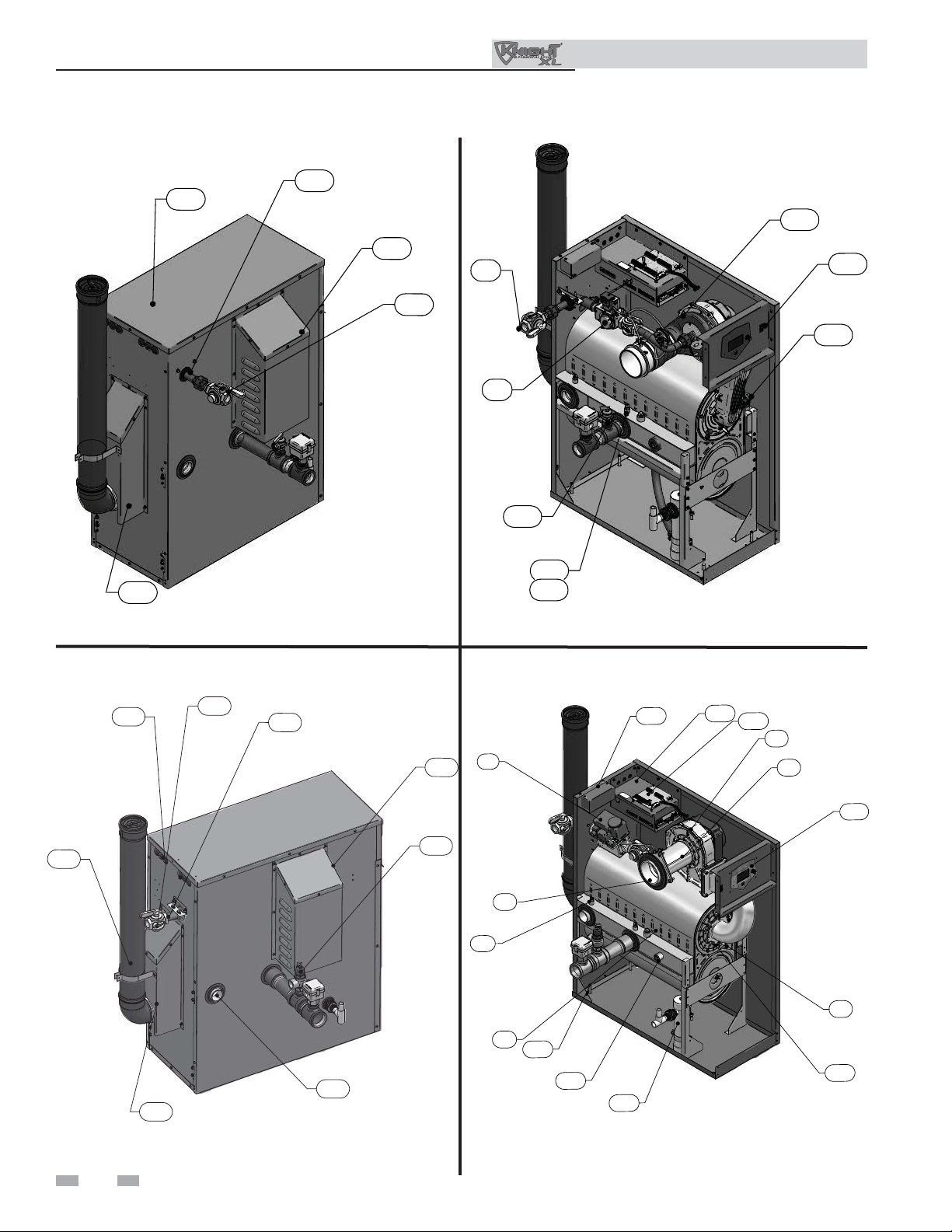
The Outdoor Knight XL - How it works... (continued)
Model 400
32
31
10
25
Front View - Model 400
20
4
IMG00405
33
19
IMG00404
11
Rear View - Model 400
20
22
36
8
4
39
7
39
13
21
24
Left Side (inside unit) - Model 400
IMG00406
26
30
2
27
IMG00407
Right Side (inside unit) - Model 400
37
16
1
3
34
17
5
Outdoor Knight XL Installation & Operation Manual
The Outdoor Knight XL - How it works...
Model 501
15
32
19
15
28
4
35
33
17
41
IMG00408
Rear View - Model 501
Models 601 - 801
23
11
31
15
29
7
39
Left Side (inside unit) - Model 501
18
29
4
18
8
20
IMG00409
16
22
3
5
10
41
14
IMG00323
1
34
21
24
IMG0
0324
IMG00324
Rear View - Models 601 - 801 Left Side (inside unit) - Models 601 - 801
6
2
30
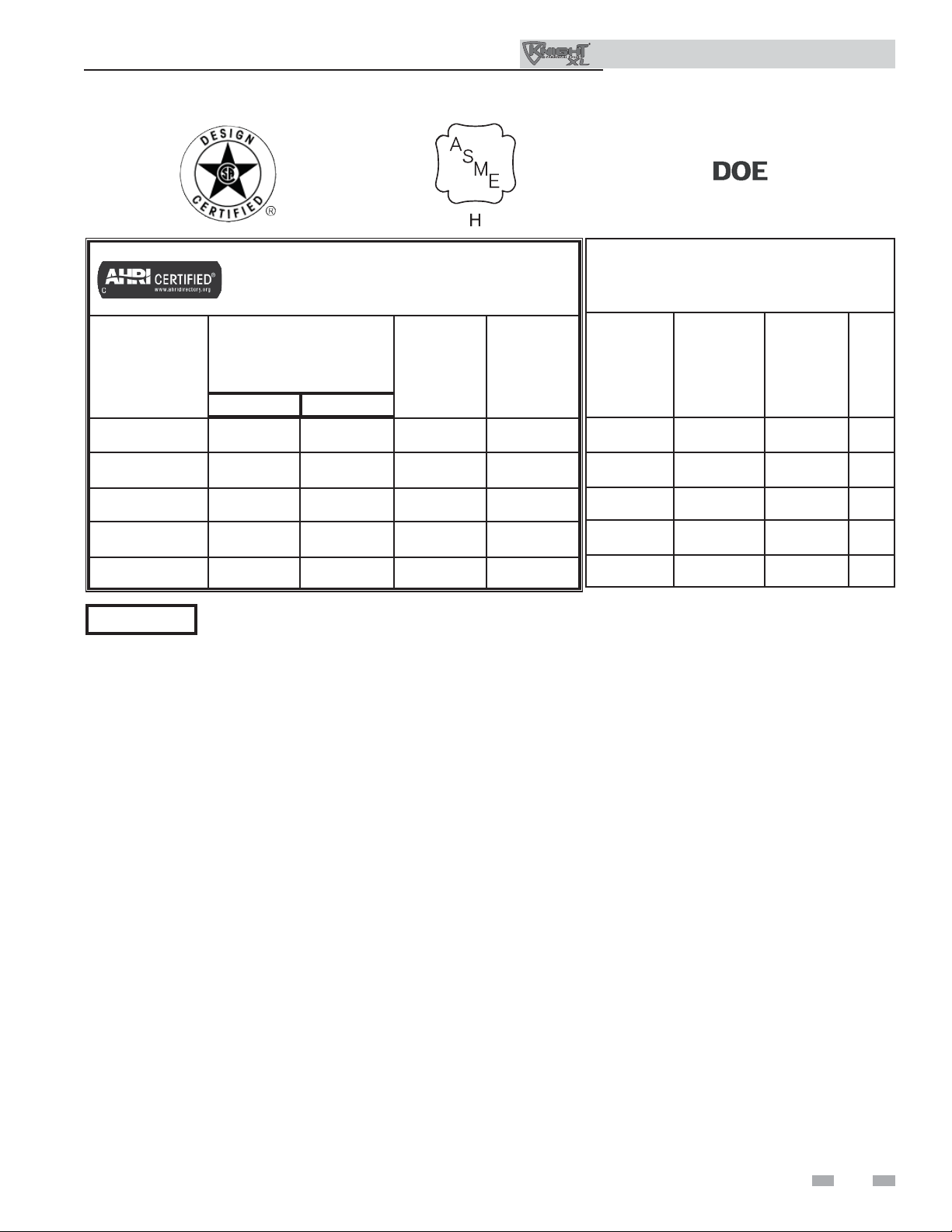
Ratings
Outdoor Knight XL Installation & Operation Manual
Outdoor Knight XL Boiler
Other Specifi cations
AHRI Rating
Model Number
Note: Change “N” to
“L” for L.P. gas models.
OKN400 80 399 370 322
OKN501 100 500 463 402
OKN601 120 600 566 493
OKN701 140 700 658 572
OKN801 160 800 748 651
NOTICE
Min Max
Maximum allowed working pressure is located on the rating plate.
Input
MBH
(Note 4)
Gross
Output
MBH
(Note 1)
Notes:
1. The ratings are based on standard test procedures prescribed by the United States Department of Energy.
Net
AHRI
Ratings
Water,
MBH
(Note 2)
Boiler Water
Content
Gallons
3.4 1-1/2" 1" 4"
4.2 1-1/2" 1" 4"
4.2 2" 1" 4"
5.0 2" 1" 4"
5.7 2" 1" 4"
Water
Connections
Gas
Connections
Air Size
2. Net AHRI ratings are based on net installed radiation of suffi cient quantity for the requirements of the building and nothing
need be added for normal piping and pickup. Ratings are based on a piping and pickup allowance of 1.15.
3. Standard Outdoor Knight XL boilers are equipped to operate from sea level to 4,500 feet only with no adjustments. The boiler
will de-rate by 4% for each 1,000 feet above sea level up to 4,500 feet.
4. Ratings have been confi rmed by the Hydronics Section of AHRI.
5. Outdoor Knight XL boilers comply with the requirements of CSD-1 Section CW-400 requirements as a temperature operation
control. The manual reset high limit provided with the Outdoor Knight XL is listed to UL353.
7
1 Determine boiler location
Outdoor Knight XL Installation & Operation Manual
Installation must comply with:
• Local, state, provincial, and national codes, laws,
regulations, and ordinances.
• National Fuel Gas Code, ANSI Z223.1 – latest edition.
• Standard for Controls and Safety Devices for Automatically
Fired Boilers, ANSI/ASME CSD-1, when required.
• National Electrical Code.
NOTICE
WARNING
WARNING
The Outdoor Knight XL gas manifold
and controls met safe lighting and other
performance criteria when the boiler
underwent tests specifi ed in ANSI Z21.13
– latest edition.
Outdoor models must be installed outdoors
only and must use the outdoor vent
assembly supplied by the manufacturer.
Personal injury or product damage may
result if any other venting is used or if an
outdoor model is used indoors. All covers,
doors and jacket panels must be properly
installed to ensure proper operation and
prevent a hazardous condition.
This product contains a condensate
management and disposal system that
may be subject to freezing if exposed
to sustained temperatures below 32°F.
Precautions should be taken to protect the
condensate trap and drain lines during
extended periods of outdoor temperatures
below 32°F.
Before locating the boiler, check:
1. Check for nearby connection to:
• System water piping
• Gas supply piping
• Electrical power
2. - Keep venting areas free of obstructions.
- Keep area clean and free of combustible and fl ammable
materials.
- To avoid a blocked air inlet or blocked fl ue condition,
keep the outdoor air inlet and fl ue outlet clear or leaves,
debris, etc.
CAUTION
CAUTION
8
Do not install outdoor models directly on
the ground. You must install the outdoor
unit on a level concrete, brick, block, or
pressure-treated wood platform.
Do not locate unit so that high winds
can defl ect off of adjacent walls, buildings
or shrubbery causing recirculation.
Recirculation of fl ue products may cause
operational problems, bad combustion or
damage to controls. Locate unit at least
3 feet (0.91m) from any wall or vertical
surface to prevent wind conditions from
affecting performance.
CAUTION
CAUTION
WARNING
3. Check area around the boiler. Remove any combustible
materials, gasoline and other fl ammable liquids.
WARNING
4. If a new boiler will replace an existing boiler, check for
and correct system problems, such as:
• System leaks causing oxygen corrosion or heat exchanger
cracks from hard water deposits.
• Incorrectly-sized expansion tank.
• This unit is not intended for installations where
temperatures may reach below 32°F (0°C). Exposure to
freezing temperatures will cause the system and boiler
to freeze and leak.
The unit must not be installed in an area
that is enclosed by walls or a fence that
will block free wind movement around
the appliance. Free movement of wind
around the outdoor unit is required
to carry away the fl ue products and
provide combustion air. The fl ue outlet/
combustion air inlet of an outdoor unit
must not be installed closer than 10 feet
from an inside corner of an L-shaped
structure. Walls or enclosed fencing may
cause eddy currents which can recirculate
the fl ue products into the combustion
air inlet. Recirculation of fl ue products
may cause operational problems, bad
combustion or non-warrantable damage
to controls.
Locate the unit at least 3 feet (0.91m)
outside any overhang.
Do not install in locations where rain
from building runoff drains will spill onto
the unit.
Do not locate the unit so that water
from sprinklers may spray directly onto
it. Water may damage controls or other
electrical components.
Do not install the unit under a deck.
Do not install the unit in a well, stairwell,
alcove, courtyard or other recessed area.
Do not install outdoor units on stack
frames. Failure to comply with the above
may result in severe personal injury, death
or substantial property damage.
Failure to keep boiler area clear and free
of combustible materials, gasoline, and
other fl ammable liquids and vapors can
result in severe personal injury, death, or
substantial property damage.
1 Determine boiler location (continued)
Outdoor Knight XL Installation & Operation Manual
Provide clearances:
Clearances from combustible materials
1. Hot water pipes—at least 1/4" (6 mm) from combustible
materials.
2. Jacket—minimum of 0" from right side and 14" from rear
side for proximity from combustible materials.
3. Vent—minimum of 1" from combustible materials.
Clearances for service access
1. If you do not provide the minimum clearances shown, it
may not be possible to service the boiler without removing
it from the space.
Recommended service clearances
Front: 30" (762mm)
Top: 24" (610mm)
Left side: 24" (610mm)
Rear: 24" (610mm)
Outdoor vent / air intake location:
WARNING
The fl ue products discharged from the
fl ue outlet on the outdoor vent may be
very hot. Avoid touching or making other
direct contact with the fl ue gases or the
vent termination. These components are
hot and direct contact can result in burns.
Under no circumstances is the manufacturer to be held
responsible for water damage in connection with this
appliance, or any of its components. If fl ooding is possible,
elevate the boiler suffi ciently to prevent water from reaching
the boiler.
Prevent combustion air contamination
Do not install unit in locations that can allow contamination
of combustion air. Refer to Table 1A for products and areas
which may cause contaminated combustion air.
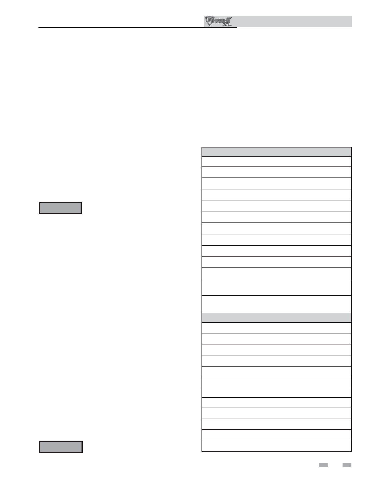
Table 1A Corrosive Contaminants and Sources
Products to avoid:
Spray cans containing chloro/fl uorocarbons
Permanent wave solutions
Chlorinated waxes/cleaners
Chlorine-based swimming pool chemicals
Calcium chloride used for thawing
Sodium chloride used for water softening
Refrigerant leaks
Paint or varnish removers
To prevent recirculation of the fl ue products into the
combustion air inlet, follow all instructions in this section.
Flue gas condensate can condense on exterior walls or on the
vent. Some discoloration or exterior building or unit surfaces
can be expected. Adjacent brick or masonry surfaces should
be protected with a rust resistant sheet metal plate.
Maintain a minimum of 24" clearance to the air inlet.
Locate the outdoor vent termination at least 48" (1.22m)
below and 48" (1.22m) horizontally from any window, door,
walkway or gravity air intake.
Locate the unit at least 10 feet (3.05m) away from any forced
inlet.
Multiple unit outdoor installations require 24" (1.22m)
clearance between each vent termination.
Clearances around outdoor installations can change with
time. Do not allow the growth of trees, shrubs or other plants
to obstruct the proper operation of the outdoor vent system.
Flooring and foundation
Flooring
The Outdoor Knight XL is approved for installation on
combustible fl ooring.
WARNING
Do not install the boiler on carpeting even
if foundation is used. Fire can result,
causing severe personal injury, death, or
substantial property damage.
Hydrochloric acid/muriatic acid
Cements and glues
Antistatic fabric softeners used in clothes dryers
Chlorine-type bleaches, detergents, and cleaning solvents
found in household laundry rooms
Adhesives used to fasten building products and other
similar products
Areas likely to have contaminants
Dry cleaning/laundry areas and establishments
Swimming pools
Metal fabrication plants
Beauty shops
Refrigeration repair shops
Photo processing plants
Auto body shops
Plastic manufacturing plants
Furniture refi nishing areas and establishments
New building construction
Remodeling areas
Garages with workshops
9
2 Prepare boiler
Outdoor Knight XL Installation & Operation Manual
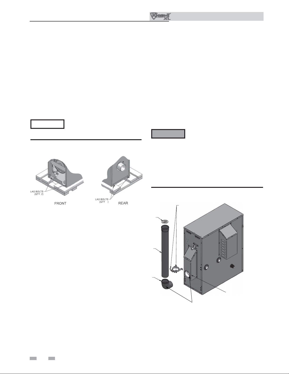
Remove boiler from wood pallet
1. After removing the outer shipping carton from the
boiler, remove the parts box.
2. Remove the front door to access the lag bolts in front
of the unit (FIG. 2-1).
3. To remove the boiler from the pallet (after removing
the front door):
a. Remove the two lag bolts from the wood pallet
inside the boiler (FIG. 2-1).
b. Detach the boiler from the lag bolts in the rear of the
unit, see FIG. 2-1.
NOTICE
Figure 2-1 Boiler Mounted on Shipping Pallet
Do not drop the boiler or bump the
jacket on the fl oor or pallet. Damage to
the boiler can result.
Install fl ue pipe assembly
Models 400 - 601
This unit is provided with all of the necessary venting
components. All components must be installed prior to
operation.
1. Locate all venting components from the installation kit
and carton.
2. Before connecting the vent pipe sections or components,
verify that the gasket is seated evenly inside the groove in
the female end of the elbow and fl ue adaptor (FIG. 2-2).
3. Remove the provided screws from the vent cover and use
them to install the vent strap (FIG. 2-2).
4. Insert the elbow into fl ue adaptor (FIG. 2-2).
CAUTION
5. Slide the vent pipe through the wall strap and insert it
into the elbow (FIG. 2-2).
6. Install the bird screen into the top of the vent.
Do NOT use grease or other lubricant
on the vent seals. Only water may be
used for this purpose. Grease or other
lubricant can make the seal brittle or
cause tearing of the seal surface which
can result in fl ue gas leakage.
Figure 2-2 Install fl ue pipe assembly - Models 400 -
VENT PIPE
ELBOW
601
WALL STRAP
AND SCREWS
FLUE
ADAPTER
NOTE: VERIFY THAT GASKET IS SEATED EVENLY
INSIDE THE GROOVE IN ELBOW AND ADAPTER
IMG00444
. 2
BIRD SCREEN
10
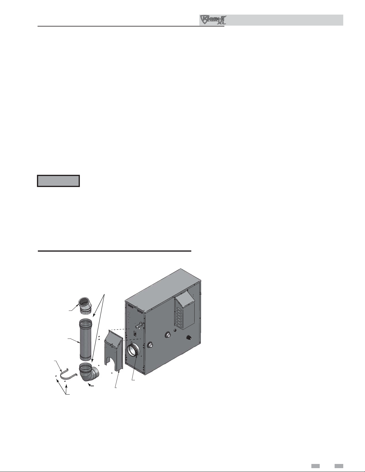
2 Prepare boiler (continued)
Models 701 - 801
1. Locate all venting components from the installation kit and
carton.
2. Before connecting the vent pipe sections or components,
verify that the gasket is seated evenly inside the groove
in the female end of the elbow and fl ue adapter
(FIG. 2-3).
3. Remove the vent cover from the back of the unit as shown in
FIG. 2-3.
4. Insert the elbow into the fl ue adapter and tighten the clamp
using a 5/16" nut driver (FIG. 2-3).
5. Re-install the vent cover removed in Step 3.
6. Remove the provided screws from the vent cover and use
them to install the wall strap (FIG. 2-3).
Outdoor Knight XL Installation & Operation Manual
CAUTION
Do NOT use grease or other lubricant on the
vent seals. Only water may be used for this
purpose. Grease or other lubricant can make
the seal brittle or cause tearing of the seal
surface which can result in fl ue gas leakage.
7. Slide the vent pipe through the wall strap and insert it into the
elbow. Tighten the clamp (FIG. 2-3).
8. Install the termination into the top of the vent and tighten the
clamp.
Figure 2-3 Install fl ue pipe assembly - Models 701 - 801
NOTE: VERIFY THAT GASKET IS SEATED EVENLY
INSIDE THE GROOVE IN ELBOW AND ADAPTER
VENT
TERMINATION
VENT PIPE
WALL
STRAP
WALL STRAP
SCREWS
ELBOW
IMG00446
CLAMP
VENT COVER
11
2 Prepare boiler
Gas conversions
Outdoor Knight XL Installation & Operation Manual
WARNING
For a boiler already installed, you must
turn off gas supply, turn off power and
allow boiler to cool before proceeding.
You must also completely test the boiler
after conversion to verify performance
as described under Start-up, Section 10
of this manual. Failure to comply could
result in severe personal injury, death, or
substantial property damage.
For the 400 Model you must install a
propane orifi ce to operate the Outdoor
Knight XL on propane gas. Verify when
installing that the orifi ce size marking
matches boiler size (Model 400 - 8.0 LP
orifi ce stamping).
Models 501 - 801 do not require an orifi ce
installation for propane operation, but
they will require a valve adjustment.
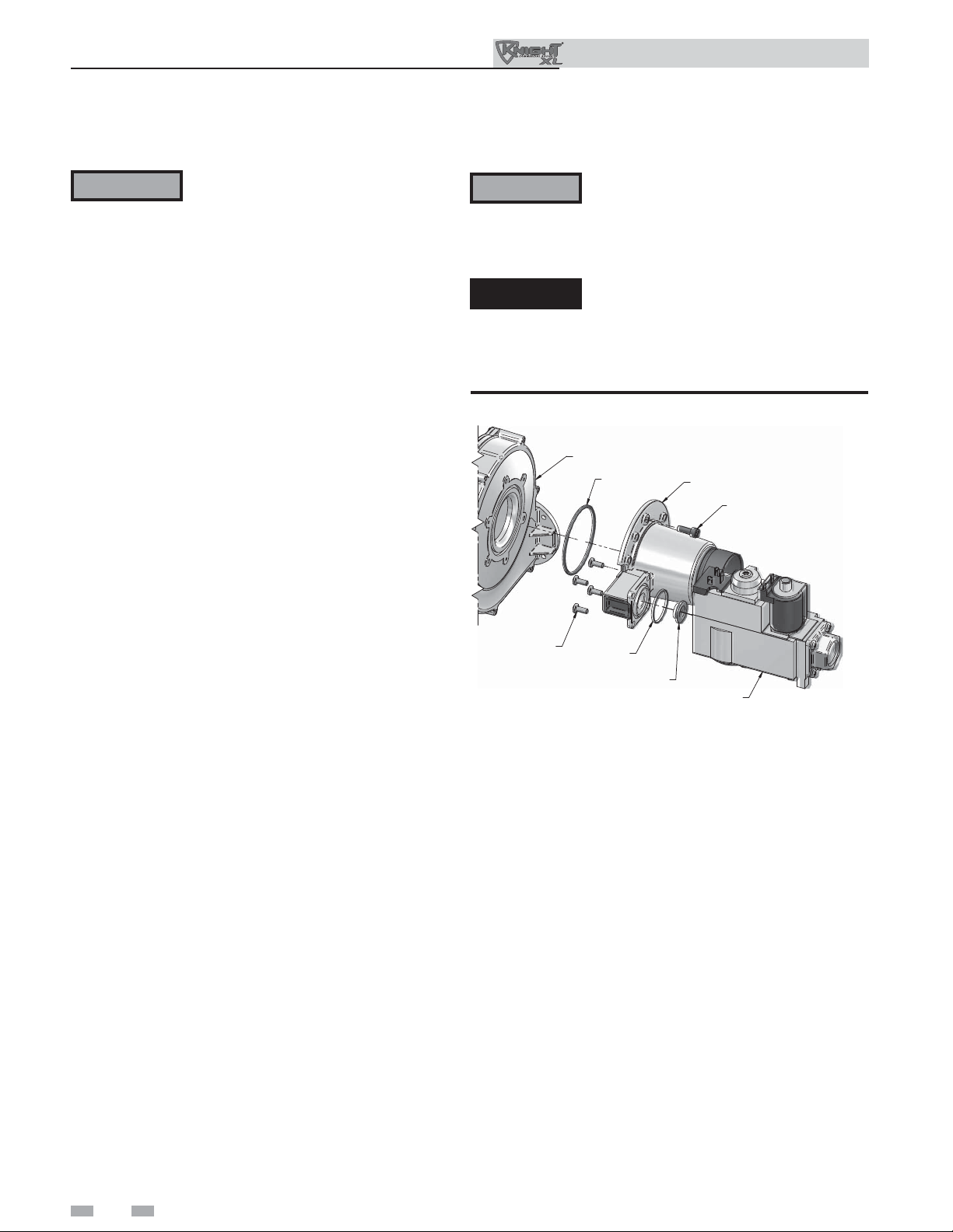
Model 400
1. Remove the top and front access covers from the unit
(tools required for removal).
2. Remove the three screws securing the venturi to the
blower. Note: When separating the venturi from the
blower, take care not to damage the O-ring inside the
blower (FIG. 2-4).
3. Remove the four star-drive screws securing the gas valve
to the venturi (FIG. 2-4).
4. Locate the propane orifi ce disk from the conversion kit
bag.Verify that the stamping on the orifi ce disk matches
the boiler size (Model 400 - 8.0 LP orifi ce stamping).
5. Remove the existing orifi ce from the O-ring in the side of
the gas valve and replace it with the orifi ce from the kit.
Position and secure the orifi ce in the valve as shown in
FIG. 2-4.
6. Reposition the gas valve against the venturi and replace
the star-drive screws (FIG. 2-4) securing the valve to the
venturi.
7. Inspect the O-ring inside the blower. Handle the O-ring
with care, do not damage. Reposition the venturi against
the blower and replace the screws securing the venturi to
the blower (FIG. 2-4).
8. After installation is complete, attach the propane
conversion label (in the conversion kit bag) next to the
boiler rating plate. Attach the LP caution label (in the
conversion kit bag) to the left side of the unit in the lower
left corner.
9. Replace the top and front access covers.
WARNING
After converting to LP, check combustion
per the Start-up procedure in Section 10
of this manual. Failure to check and verify
combustion could result in severe personal
injury, death, or substantial property damage.
DANGER
Model 400: Inspect the O-ring when the
blower is disassembled. The O-ring must
be in good condition and must be installed.
Failure to comply will cause a gas leak,
resulting in severe personal injury or death.
Figure 2-4 Installing Propane Orifi ce - Model 400
BLOWER
SCREWS
QTY. 4
O-RING
O-RING
BRASS ORIFICE
VENTURI
SCREWS
QTY. 3
GAS VALVE
12
2 Prepare boiler (continued)
Outdoor Knight XL Installation & Operation Manual
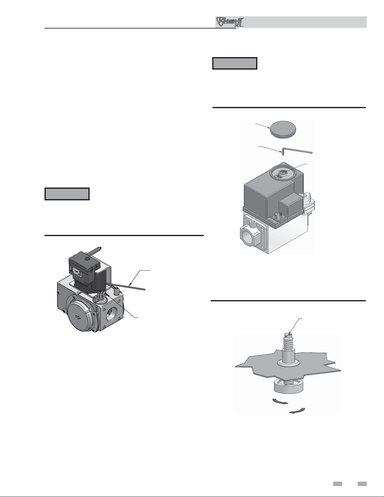
Model 501
1. Remove the top access cover from the unit (Philips Head
screwdriver required for removal).
2. Turn the adjustment screw on the gas valve clockwise until
it stops. Then turn the adjustment screw counterclockwise
four and three quarter (4 3/4) turns (see FIG. 2-5).
3. Use a combustion analyzer to verify CO2 is within the range
of 9.6 – 10.5%. If not, adjust the screw counterclockwise
incrementally to raise CO2 and clockwise to lower CO2
(FIG. 2-5).
4. After adjustment is complete, attach the propane conversion
label (in the conversion kit bag) next to the boiler rating
plate. Attach the LP caution label (in the conversion kit bag)
to the left side of the unit in the lower left corner.
5. Replace the top access cover.
WARNING
Figure 2-5 Gas Valve Adjustment - Model 501
After converting to LP, check combustion
per the Start-up procedure in Section 10
of this manual. Failure to check and verify
combustion could result in severe personal
injury, death, or substantial property
damage.
WARNING
After converting to LP, check combustion
per the Start-up procedure in Section
10 of this manual. Failure to check and
verify combustion could result in severe
personal injury, death, or substantial
property damage.
Figure 2-6 Gas Valve Adjustment - Models 601 - 801
COVER
ALLEN WRENCH
ADJUSTMENT SCREW
ALLEN WRENCH
ADJUSTMENT SCREW
Models 601 - 801
1. Remove the top access cover from the unit (Philips Head
screwdriver required for removal).
2. Remove the cover on top of the gas valve (FIG. 2-6).
3. Turn the adjustment screw on top of the gas valve clockwise
one and three quarter (1 3/4) turns on the 601 Model, one
and a half (1 1/2) turns on the 701 Model, and one turn on
the 801 Model (see FIG. 2-6).
4. Use a combustion analyzer to verify CO2 is within the range
of 9.6 – 10.5%. If not, adjust the screw counterclockwise
incrementally to raise CO2 and clockwise to lower CO2
(FIG. 2-6).
5. After adjustment is complete, attach the propane conversion
label (in the conversion kit bag) next to the boiler rating
plate. Attach the LP caution label (in the conversion kit
bag) to the left side of the unit in the lower left corner.
6. Replace the gas valve cover along with the top access cover.
Leveling the boiler
1. Set the boiler in place and check level.
a) Adjust legs if necessary to level boiler, see FIG. 2-7
below.
Figure 2-7 Leveling Legs on the Boiler
SCREWDRIVER
SLOT
LOWER
RAISE
13

3 Hydronic piping
Outdoor Knight XL Installation & Operation Manual
System water piping methods
The Outdoor Knight XL is designed to function in a closed
loop pressurized system not less than 12 psi (83 kPa). A
temperature and pressure gauge is included to monitor
system pressure and outlet temperature and should be
located on the boiler outlet.
It is important to note that the boiler has a minimal amount
of pressure drop which must be fi gured in when sizing
the circulators. Each boiler installation must have an air
elimination device, which will remove air from the system.
Install the boiler so the gas ignition system components
are protected from water (dripping, spraying, etc.) during
appliance operation or basic service of circulator replacement,
valves, and others.
Observe a minimum of 1/4 inch (6 mm) clearance around all
un-insulated hot water pipes when openings around the pipes
are not protected by non-combustible materials.
Low water cutoff device
On a boiler installed above radiation level, some states and
local codes require a low water cutoff device at the time of
installation.
Chilled water system
If the boiler supplies hot water to heating coils in air handler
units, fl ow control valves or other devices must be installed to
prevent gravity circulation of heater water in the coils during
the cooling cycle. A chilled water medium must be piped in
parallel with the heater.
Freeze protection
Freeze protection for new or existing systems must use
glycol that is specially formulated for this purpose. This
includes inhibitors, which prevent the glycol from attacking
the metallic system components. Make certain to check that
the system fl uid is correct for the glycol concentration and
inhibitor level. The system should be tested at least once
a year and as recommended by the producer of the glycol
solution. Allowance should be made for the expansion of the
glycol solution in the system piping.
WARNING
Use only inhibited propylene glycol
solutions, which are specifi cally formulated
for hydronic systems. Ethylene glycol is
toxic and can attack gaskets and seals used
in hydronic systems.
14
General piping information
Basic steps are listed below along with illustrations on the
following pages (FIG.’s 3-7 through 3-11), which will guide
you through the installation of the Outdoor Knight XL
(reference FIG.’s 3-4A and 3-4B).
1. Connect the system return marked “Inlet”.
2. Connect the system supply marked “Outlet”.
3. Install purge and balance valve or shutoff valve and drain
on system return to purge air out of each zone.
4. Install a backfl ow preventer on the cold feed make-up
water line.
5. Install a pressure reducing valve on the cold feed make-up
water line, (15 psi (103 kPa) nominal). Check temperature
and pressure gauge (shipped separately), which should
read a minimum pressure of 12 psi (83 kPa).
6. Consult the factory for a pump and/or pump cover. If a
fi eld-supplied pump is used, install per the manufacturer’s
specifi cations in regard to indoor or outdoor location. An
outdoor rated pump is recommended.
7. Install a circulator as shown on the piping diagrams in this
section. Make sure the circulator is properly sized for the
system and friction loss.
8. Install an expansion tank on the system supply. Consult the
tank manufacturer’s instruction for specifi c information
relating to tank installation. Size the expansion tank for the
required system volume and capacity.
9. Install an air elimination device on the system supply.
10. Install a drain valve at the lowest point of the system.
Note: The boiler cannot be drained completely of water
without purging the unit with an air pressure of 15 psi
(103 kPa).
11. This appliance is supplied with a relief valve sized in
accordance with ASME Boiler and Pressure Vessel Code,
Section IV (“Heating Boilers”). Pipe the discharge of the
safety relief valve to prevent injury in the event of pressure
relief. Pipe the discharge to a drain. Provide piping that is
the same size as the safety relief valve outlet. Never block
the outlet of the safety relief valve.
WARNING
12. On any pre-existing system, it is good practice to install
a fi eld supplied strainer to prevent damage to the heat
exchanger.
See the piping illustrations included in this section, FIG.’s
3-7 and 3-11 for suggested guidelines in piping the Outdoor
Knight XL.
NOTICE
The relief valve, tee and any other necessary
fi ttings are shipped in the install kit with the
boiler and are to be fi eld installed (FIG.’s
3-1 and 3-2).
Please note that these illustrations are
meant to show system piping concept only,
the installer is responsible for all equipment
and detailing required by local codes.
3 Hydronic piping (continued)
Outdoor Knight XL Installation & Operation Manual
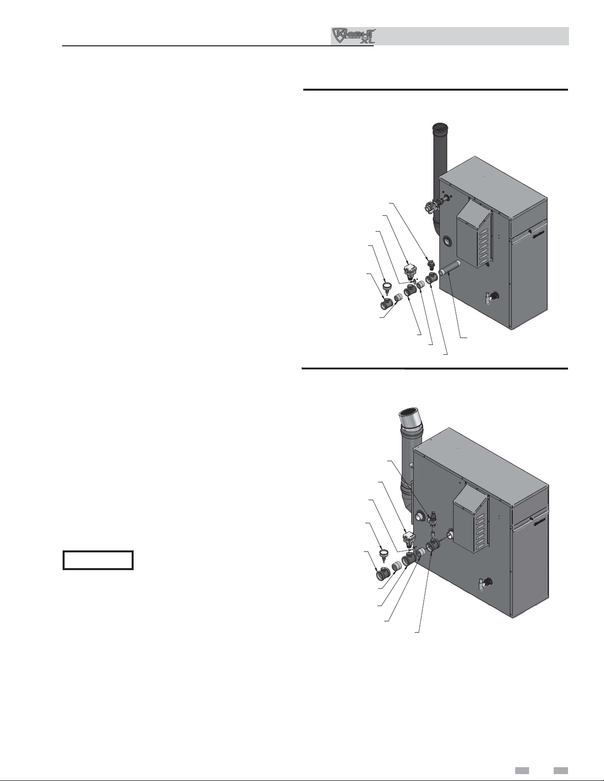
Flow switch, relief valve and temperature
and pressure gauge installation
Basic steps are listed below to guide you through the
installation of the fl ow switch, relief valve, and temperature
and pressure gauge provided with the unit.
1. For Models 400 - 501 install the close nipple on the
outlet connection of the heat exchanger. Install the tee
with the 3/4 inch fi tting positioned vertically and on
the top as shown in FIG. 3-1. For Models 601 - 801
install the tee directly to the outlet connection of the
heat exchanger with the 3/4 inch fi tting positioned
vertically and on the top (see FIG. 3-2).
2. For Models 701 - 801 install the 3/4 inch close nipple
in the tee. Install the relief valve on the 3/4 inch close
nipple (FIG. 3-2). For Models 400 - 601 install the
relief valve directly into the 3/4 inch fi tting on the tee
(FIG. 3-1).
3. Install the close nipple on the downstream side of
the relief valve tee (FIG. 3-1).
4. Install the tee with the 1 inch fi tting positioned
vertically and on the top (FIG. 3-1).
5. Attach paddle #3 to the fl ow switch per the
manufacturer’s instructions.
6. Install the assembled fl ow switch into the 1 inch fi tting
of the tee installed in Step 4 (see FIG. 3-1).
7. Install a fi eld provided close nipple on the downstream
side of the fl ow switch (see FIG.’s 3-1 and 3-2).
8. Install a fi eld provided tee with the gauge fi tting
positioned vertically and on the top (FIG.’s 3-1 and
3-2)
9. Install the temperature and pressure gauge provided
with the unit into the top fi tting of the tee (a bushing
may be necessary) installed in Step 8 (FIG.’s 3-1 and
3-2).
NOTICE
Be sure to install the fl ow switch so
that the arrow on the fl ow switch is
pointing in the direction of the fl ow
(see FIG. 3-3).
Figure 3-1 Flow Switch, Relief Valve and Temperature and
Pressure Gauge Installation_Models 400 - 501
RELIEF VALVE
FLOW SW ITCH
PADDLE
TEMPERATURE &
PRESSURE GAUGE
TEE WITH FITTING
ON TOP
(FIELD PROVIDED)
CLOSE NIPPLE
(FIELD PROVIDED)
TEE WITH 1" FITT ING ON TOP
CLOSE NIPPLE
TEE WITH 3/4"
FITTING ON TOP
8' NIPPLE
(REQUIRED FOR MODELS 400 - 701)
IMG00390
Figure 3-2 Flow Switch, Relief Valve and Temperature and
Pressure Gauge Installation_Models 601 - 801
RELIEF VALVE
FLOW SWI TCH
PADDLE
TEMPERATURE &
PRESSURE GAUGE
TEE WITH FITTING
(FIELD PROVIDED)
CLOSE NIPPLE
(FIELD PROVIDED)
TEE WITH 1" FITTING
ON TOP
CLOSE NIPPLE
TEE WITH 3/4"
FITTING ON TOP
IMG00389
15
3 Hydronic piping
Outdoor Knight XL Installation & Operation Manual
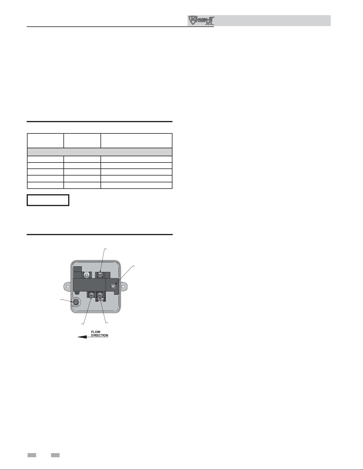
Flow switch adjustment
Refer to Table 3A for the proper setting of the sensitivity
screw. For reference, the position of the screw prior to setting
should be turned clockwise with a Phillips driver until it stops
(FIG. 3-3). Proceed to turn the screw counterclockwise the
amount of turns listed in Table 3A based on the model.
Consult the manufacturer’s instructions for wiring the fl ow
switch to your system.
Table 3A Paddle Size / Sensitivity Screw Adjustment
MODEL PADDLE SIZE
Note: Paddles are included with the fl ow switch.
400 #3 7½ turns
501 #3 5½ turns
601 #3 7¼ turns
701 #3 5¼ turns
801 #3 3¼ turns
NOTICE
Turn the sensitivity screw clockwise to
increase the fl ow rate required to activate
the switch. Turn the sensitivity screw
counterclockwise to decrease the fl ow rate
required to activate the switch.
Figure 3-3 Flow Switch Adjustment
SENSITIVITY SCREW
ADJUSTMENT
NORMALLY
OPEN
SENSITIVITY
ADJUSTMENT
Near boiler piping components
1. Boiler system piping:
Boiler system piping MUST be sized per the pipe
requirements listed in Table 3B. Reducing the pipe size
can restrict the fl ow rate through the boiler, causing
inadvertent high limit shutdowns and poor system
performance. Flow rates are based on 20 feet (6 m) of
piping, 4 - 90° elbows, and 2 - fully ported ball valves.
2. Boiler system circulating pump:
(Field supplied.) The boiler circulating pump should be
based on 20 feet (6 m) of piping, 4 - 90° elbows, and
2 - fully ported ball valves.
3. Domestic hot water circulating pump:
(Field supplied.) The pump MUST be sized to meet
the specifi ed minimum fl ow requirements listed in
FIG.’s 3-5 and 3-6. Consult the indirect water heater
operating guide to determine fl ow characteristics for the
selected product used.
4. Variable speed boiler system circulator:
Outdoor Knight XL boilers are capable of controlling
a variable speed boiler system circulator. Variable speed
circulators MUST be sized to meet the specifi ed minimum
fl ow requirements listed in FIG.’s 3-5 and 3-6 on page 16
at full speed.
5. Boiler isolation valves:
Field supplied. Full port ball valves are required. Failure
to use full port ball valves could result in a restricted fl ow
rate through the boiler.
GROUND
16
COMMON
NORMALLY
CLOSED
6. Check valves:
Field supplied. Check valves are recommended for
installation as shown in FIG.’s 3-7 through 3-11. Failure
to install check valves could result in a reverse fl ow
condition during pump(s) off cycle.
7. Domestic indirect hot water isolation valves:
Field supplied. Full port ball valves are required. Failure
to use full port ball valves could result in a restricted fl ow
rate through the boiler.
8. Anti-scald mixing valve:
Field supplied. An anti-scald mixing valve is
recommended when storing domestic hot water above
115°F (46°C).
9. Unions:
Field supplied. Recommended for unit serviceability.
10. Temperature and pressure gauge:
Factory supplied. The temperature and pressure gauge is
shipped loose. It is the responsibility of the contractor to
install the temperature and pressure gauge on the boiler
water outlet.
11. Pressure relief valve:
Factory supplied. The pressure relief valve is sized to
ASME specifi cations.
3 Hydronic piping (continued)
Outdoor Knight XL Installation & Operation Manual
12. Boiler purge valve:
Field supplied. The boiler purge valve is used to
remove entrapped air from the heat exchanger during
start-up.
13. System temperature sensor:
Lochinvar supplies a system temperature sensor. The
sensor is to be installed in the heating loop downstream
from the boiler hot water piping and heating loop
junction. The sensor should be located far enough
downstream to sense system diluted water temperature.
14. Y-Strainer:
Field supplied. A Y-strainer or equivalent multipurpose
strainer is recommended at the inlet of the heat exchanger
to remove system particles from older hydronic systems
and protect newer systems.
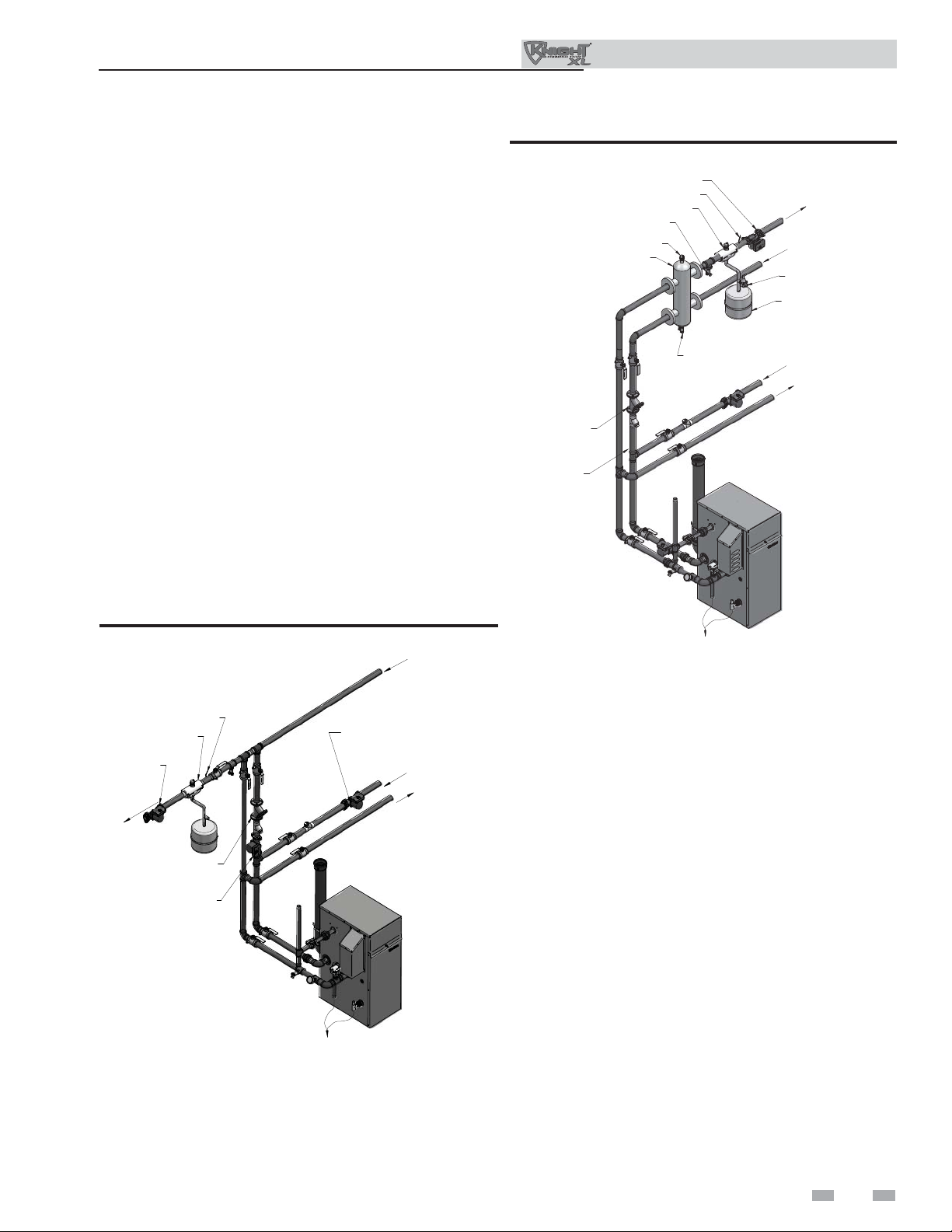
Circulator sizing
The Outdoor Knight XL heat exchanger does have a pressure
drop, which must be considered in your system design. Refer
to the graphs in FIG’s 3-5 and 3-6 for pressure drop through
the Outdoor Knight XL heat exchanger.
Figure 3-4B Near Boiler Piping w/Low Loss Header
SYSTEM PUMP
LOW LOSS HEADER
(TYPICAL)
Y-STRAINER
(RECOMMENDED)
BOILER PUMP
SYSTEM SENSOR
AIR SEPARATOR
DRAIN
(TYPICAL)
AIR VENT VALVE
DRAIN
VALVE
FAST FILL VALVE
EXPANSION TANK
F
O
T
S
M
O
E
R
T
F
S
Y
S
M
O
R
O
T
M
E
ST
Y
M
INDIRECT
DOMESTIC
HOT WATER
TANK
Near boiler piping connections
Figure 3-4A Near Boiler Piping w/Y-Strainer
M
M
O
E
R
T
F
S
Y
S
AIR SEPARATOR
SYSTEM PUMP
O
T
M
E
T
S
Y
S
SYSTEM SENSOR
Y-STRAINER
(RECOMMENDED)
BOILER PUMP
TO FLOOR
DRAIN
DOMESTIC HOT
WATER PUMP
IMG00413
M
O
R
F
O
T
INDIRECT
DOMESTIC
HOT WATER
TANK
IMG00391
TO FLOOR
DRAIN
Variable speed pump option
Variable speed pump setup
Before operation, ensure the following:
- Pump is set for an input signal of 0 - 10VDC
by the dip switches on the pump control
- Pump is set for external signal control
(if applicable)
- Pump is set for linear output (if applicable)
- If pump does not come equipped with a
0 - 10 VDC input option, an optional module
will be required from the vendor
SMART SYSTEM / Multi-temperature
loop control option
The Outdoor Knight XL boiler is capable of producing
up to three (3) set point temperatures to meet different
space heating demands. When using more than one
temperature demand it is necessary to protect the
lower temperature loop from overheating. To help
aid with this protection, Lochinvar offers the MultiTemperature Loop Control Board Kit (RLY30086).
17
 Loading...