


IFB/IFW-i&s-05
INSTALLATION AND SERVICE MANUAL
Intelli-Fin®
Hot Water Heating Boilers
Domestic Hot Water Supply Boilers
1,500,000 — 1,700,000 — 2,000,000 Btu/hr Models
FIG. 1 Front View
Installation and service must be performed by a qualified service installer, service agency or the gas supplier.
WARRANTY
Factory warranty (shipped with unit) does not apply to units improperly installed or improperly operated.
Experience has shown that improper installation or system design, rather than faulty equipment, is the cause of most operating problems.
1. |
Excessive |
water |
hardness |
causing |
a lime/scale |
||||
|
build-up in the copper tube is not the fault of the |
||||||||
|
equipment |
and |
is |
not |
covered |
under |
the |
||
|
manufacturer’s warranty. (See Water Treatment and |
||||||||
|
Water Chemistry) |
|
|
|
|
|
|
||
2. |
Excessive |
pitting |
and |
erosion |
on |
the |
inside |
of the |
|
|
copper |
tube may |
be |
caused |
by |
too |
much |
water |
|
|
velocity |
through |
the tubes and is not covered by |
||||||
|
the manufacturer’s |
warranty (See Boiler Flow Rates |
|||||||
|
and Temperature Rise for flow requirements). |
|
|
||||||
FIG. 2 Rear View
SPECIAL INSTRUCTIONS
TO OWNER
NOTE: Retain this manual for future reference.
This manual supplies information for the installation, operation and servicing of the appliance. It is strongly recommended that this manual be reviewed completely before proceeding with an installation.
WARNING
IMPROPER INSTALLATION, ADJUSTMENT, ALTERATION, SERVICE OR MAINTENANCE can cause injury or property damage. Refer to this manual. For assistance or additional information, consult a qualified installer, service agency or the gas supplier.
1

TABLE OF CONTENTS
Warranty .......................................................................... |
1 |
Safety Warnings .............................................................. |
3 |
Codes .......................................................................... |
3 |
Installation Requirements ............................................ |
4 |
Location .................................................................... |
4 |
Clearances ................................................................ |
4 |
Combustion/Ventilation Air Requirements .............. |
5 |
Construction Air Filter.............................................. |
7 |
Venting Systems ............................................................ |
8 |
Category IV Venting ........................................................ |
9 |
Flue Pipe Materials............................................ |
9 |
Installation Guidelines ...................................... |
9 |
Vent Length Requirements ................................ |
10 |
Drain Tee Installation ........................................ |
10 |
Vertical Terminations ........................................ |
11 |
Sidewall Terminations ...................................... |
12 |
Direct Vent Systems ........................................................ |
13 |
Air Inlet Pipe Materials .................................... |
14 |
Air Inlet Pipe Length Requirements.................. |
14 |
Vertical Direct Vent .................................................. |
15 |
Location Requirements...................................... |
15 |
Multiple Direct Vent Installations...................... |
16 |
Horizontal Direct Vent .............................................. |
16 |
Location Requirements...................................... |
16 |
Multiple Direct Vent Installations...................... |
18 |
Intelli-Vent Systems.................................................. |
18 |
Materials............................................................ |
18 |
Length Requirements ........................................ |
18 |
Vertical Flue - Sidewall Air .............................. |
19 |
Sidewall Flue - Rooftop Air .............................. |
20 |
Sidewall Flue - Sidewall Air.............................. |
21 |
Gas Supply .................................................................... |
23 |
Gas Pressures and Piping .................................. |
23 |
Manifold Pressure.............................................. |
23 |
Supply Pressure Measurement .......................... |
25 |
Manifold Pressure Measurement ...................... |
26 |
Water Connections .......................................................... |
27 |
Heat Exchangers .............................................................. |
28 |
Integral Bypass ................................................................ |
29 |
Valve and Pump ................................................ |
29 |
Synchronization ................................................ |
29 |
Set-up Maximum Flow...................................... |
30 |
Bypass Operation .............................................. |
31 |
Minimum Water Temperatures .................................. |
31 |
Flow Switch .................................................................... |
32 |
Low Water Cut-Off .......................................................... |
32 |
Gas Train.......................................................................... |
32 |
Relief Valve...................................................................... |
33 |
Ratio Gas Valve ........................................................ |
33 |
Diaphragm Gas Valve .............................................. |
33 |
Electrical Requirements .................................................. |
34 |
Jacket .......................................................................... |
34 |
Components and Controls ............................................ |
35 |
Variable Frequency Drive.................................. |
36 |
Low Air Pressure Switch .................................. |
37 |
Gas Pressure Switches ...................................... |
37 |
Excel 10 Boiler Interface Controller ................ |
37 |
Manual Override Control .................................. |
|
39 |
Temperature Adjustment.................................... |
|
39 |
Command Display ............................................ |
|
39 |
Password .................................................... |
|
40 |
Changeable Points...................................... |
|
40 |
Data Points in Display................................ |
|
41 |
Status Points — Operation ........................ |
|
43 |
Status Points — Alarm .............................. |
|
44 |
Outdoor Reset Function ............................ |
|
44 |
Multiple Appliance Installations........................ |
|
45 |
Sequencing Options.................................... |
|
45 |
E-Bus Connection ...................................... |
|
46 |
Temperature Limit Control................................ |
|
48 |
Hot Surface Ignition Control ............................ |
|
48 |
Hot Surface Igniter.............................. |
|
49 |
Diagnostic Status LED........................ |
|
49 |
Operation/Diagnostic Lights and Switches |
......50 |
|
Burner Assembly .............................................. |
|
51 |
Combustion Air Blower .................................... |
|
52 |
Condensate Management System...................... |
|
53 |
Installation and Operation .................. |
|
53 |
Condensate Trap Installation |
.............. |
54 |
Lighting Instructions .................................................... |
|
55 |
Sequence of Operation .................................................. |
|
57 |
Maintenance ............................................................ |
|
58 |
Vent System ............................................................ |
|
58 |
Flame Patterns .......................................................... |
|
58 |
Burner Cleaning........................................................ |
|
59 |
Heat Exchanger Inspection ...................................... |
|
61 |
Lubrication ............................................................ |
|
62 |
Combustion Air Measurements ................................ |
|
62 |
Freeze Protection ...................................................... |
|
63 |
Heating Boiler ............................................................ |
|
64 |
Piping ............................................................ |
|
64 |
Piping Length and Diameter .................................... |
|
65 |
Integral Pump Limitations ................................ |
|
65 |
Boiler Pump Operation...................................... |
|
65 |
Primary/Secondary Piping ................................ |
|
66 |
Minimum Water Temperatures .......................... |
|
66 |
Three Way Valves.............................................. |
|
67 |
Boiler Flow Rates.............................................. |
|
67 |
Placing the Boiler in Operation ........................ |
|
68 |
Boiler Temperature Control .............................. |
|
69 |
Water Heater/Domestic Hot Water Supply Boiler |
....70 |
|
Typical Piping.................................................... |
|
70 |
Set-up Maximum Flow...................................... |
|
70 |
Temperature Rise .............................................. |
|
71 |
Water Chemistry................................................ |
|
72 |
Piping Requirements ........................................ |
|
73 |
Pump Operation ................................................ |
|
74 |
Temperature Adjustment.................................... |
|
75 |
Minimum Inlet Temperatures ............................ |
|
75 |
Risk of Scald Warnings .................................... |
|
76 |
Relief Valve ...................................................... |
|
76 |
Ladder Diagram ............................................................ |
|
77 |
Wiring Diagram ............................................................ |
|
78 |
Revision Notes .............................................. |
Back Cover |
|
2

CHECKING EQUIPMENT
Upon receiving equipment, check for signs of shipping damage. Pay particular attention to parts accompanying the boiler, which may show signs of being hit or otherwise being mishandled. Verify total number of pieces shown on packing slip with those actually received. In case there is damage or a shortage, immediately notify carrier.
DO NOT
Do not use this appliance if any part has been under water. The possible damage to a flooded appliance can be extensive and present numerous safety hazards. Any appliance that has been under water must be replaced.
WARNING
If the information in this manual is not followed exactly, a fire or explosion may result causing property damage, personal injury or loss of life.
This appliance MUST NOT be installed in any location where gasoline or flammable vapors are likely to be present, unless the installation is such to eliminate the probable ignition of gasoline or flammable vapors.
WHAT TO DO IF YOU SMELL GAS
•Do not try to light any appliance.
•Do not touch any electric switch: do not use any phone in your building.
•Immediately call your gas supplier from a neighbor’s phone. Follow the gas supplier’s instructions.
•If you cannot reach your gas supplier, call the fire department.
Installation and service must be performed by a qualified installer, service agency or the gas supplier.
OWNER WARNING
The information contained in this manual is intended for use by qualified professional installers, service technicians or gas suppliers. Consult your local expert for proper installation or service procedures.
IMPORTANT
Consult and follow local Building and Fire Regulations and other Safety Codes that apply to this installation. Contact the local gas utility company to authorize and inspect all gas and flue connections.
A gas appliance that draws combustion air from the equipment room where it is installed must have a supply of fresh air circulating around it during burner operation for proper gas combustion and proper venting.
WARNING
Should overheating occur or the gas supply fail to shut off, DO NOT turn off or disconnect the electrical supply to the pump. Instead, shut off the gas supply at a location external to the appliance.
WARNING
To minimize the possibility of serious personal injury, fire or damage to your appliance, never violate the following safety rules.
1.Boilers and water heaters are heat producing appliances. To avoid damage or injury, do not store materials against the appliance or the vent-air intake system. Use proper care to avoid unnecessary contact (especially children) with the appliance and vent-air intake components.
2.Never cover your appliance, lean anything against it, store trash or debris near it, stand on it or in any way block the flow of fresh air to your appliance.
3.UNDER NO CIRCUMSTANCES must flammable materials such as gasoline or paint thinner be used or stored in the vicinity of this appliance, vent-air intake system or any location from which fumes could reach the appliance or vent-air intake system.
CODES
The equipment shall be installed in accordance with those installation regulations in force in the local area where the installation is to be made. These shall be carefully followed in all cases. Authorities having jurisdiction shall be consulted before installations are made. In the absence of such requirements, the installation shall conform to the latest edition of the National Fuel Gas Code,ANSI Z223.1 and/or CAN/CGA-B149 Installation Code. Where required by the authority having jurisdiction, the installation must conform to American Society of Mechanical Engineers Safety Code for Controls and Safety Devices for Automatically Fired Boilers, ASME CSD-1. All boilers conform to the latest edition of the ASME Boiler and Pressure Vessel Code, Section IV. Where required by the authority having jurisdiction, the installation must comply with the CSA International, CAN/CGA-B149 and/or local codes. This appliance meets the safe lighting performance criteria with the gas manifold and control assembly provided, as specified in the ANSI standards for gas-fired units, ANSI Z21.13.
3
INSTALLATION PROCEDURE
LOCATION OF UNIT
1.Locate the appliance so that if water connections should leak, water damage will not occur. When such locations cannot be avoided, it is recommended that a suitable drain pan, adequately drained, be installed under the unit. The pan must not restrict combustion airflow. Under no circumstances is the manufacturer to be held responsible for water damage in connection with this unit, or any of its components.
2.The appliance must be installed so that the ignition
system components are protected from water (dripping, spraying, etc.) during appliance operation and service (circulator replacement, control replacement, etc.).
3.Appliances located in a residential garage and in adjacent spaces that open to the garage and are not part of the living space of a dwelling unit must be installed so that all burners and burner ignition devices have a minimum clearance of not less than 18" (46cm) above the floor. The appliance must be located or protected so that it is not subject to physical damage by a moving vehicle.
4.DO NOT install this appliance in any location where gasoline or flammable vapors are likely to be present.
5.The appliance must be installed on a level floor. Combustible floor locations may be used. Maintain required clearances from combustible surfaces.
6. |
The |
appliance |
must |
not |
be |
installed |
|
on |
carpet. |
||
7. |
The |
appliance |
must |
be |
installed |
indoors |
where |
it |
|||
|
is protected from exposure to |
wind, |
rain |
and |
|||||||
|
weather. |
|
|
|
|
|
|
|
|
|
|
8. |
This |
appliance |
may |
condense |
the |
products |
of |
||||
|
combustion when operating |
at |
water |
temperatures |
|||||||
|
below 130°F (54.4°C). Ensure that the appliance is |
||||||||||
|
located near |
an |
acceptable |
drain |
where |
the |
|||||
|
condensate from the heat exchanger |
and |
venting |
||||||||
|
system may be properly collected, neutralized and |
||||||||||
|
disposed. |
|
|
|
|
|
|
|
|
|
|
TABLE - A
Clearances from
Combustible Construction:
Right Side - 0"
Rear - 9" (23 cm) (Minimum 24" (0.61 m) suggested for service to pump and components)
Left Side - 0"
Front - ALCOVE* (Minimum 24" (0.61 m) suggested for service)
Flue - 1" (25.4 mm)
Hot Water Pipes - 1" (25.4 mm)
*An ALCOVE is a closet without a door.
RECOMMENDED SERVICE CLEARANCES
FIG. 3 Recommended Service Clearances - Front |
FIG. 4 Recommended Service Clearances - Rear |
|
|
4
NOTE
Clearances from combustible construction are noted on the appliance rating plate.
Maintain minimum specified clearances for adequate operation. All installations must allow sufficient space for servicing the vent connections, water pipe connections, integral circulating pump, bypass piping and other auxiliary equipment, as well as the appliance. The clearance labels on each appliance note the same service and combustible clearance requirements as shown in the clearances from combustion construction table.
Multiple appliances may be installed in a modular boiler or water heater installation. Multiple appliances may be installed side by side with no clearance between adjacent appliances because this appliance is approved for zero clearance from combustible surfaces and no service access is required from the sides.
Consult the venting section of the manual for specific installation instructions for the appropriate type of venting system that you will be using. Direct Vent and Intelli-Vent venting systems require installation with Category IV flue pipe, sealed air inlet pipe and air inlet caps, which must meet the manufacturer’s specifications.
COMBUSTION AND VENTILATION
AIR REQUIREMENTS FOR
APPLIANCES DRAWING AIR FROM
THE EQUIPMENT ROOM
Provisions for combustion and ventilation air must be in accordance with Section 5.3, Air for Combustion and Ventilation, of the latest edition of the National Fuel Gas Code, ANSI Z223.1, in Canada, the latest edition of CAN/CGA Standard B149 Installation Code for Gas Burning Appliances and Equipment, or applicable provisions of the local building codes.
The equipment room MUST be provided with properly sized openings to assure adequate combustion air and proper ventilation when the unit is installed with a basic Category IV venting system.
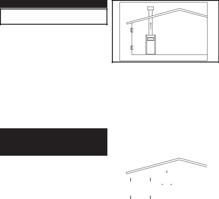
FIG. 5 Combustion Air Direct from Outside |
|
|
|
|||||||||||||||||||
1. If |
air |
is taken |
directly |
from |
outside the building |
|||||||||||||||||
|
with no duct, provide two permanent openings: |
|
|
|
||||||||||||||||||
|
a. |
Combustion |
air opening, with a minimum |
free |
||||||||||||||||||
|
|
area |
of |
one |
square |
inch |
per |
4000 |
Btu |
input |
||||||||||||
|
|
(5.5 cm2 per kW). This opening must be located |
||||||||||||||||||||
|
|
within 12" (30cm) of the bottom of |
the |
|||||||||||||||||||
|
|
enclosure. |
|
|
|
|
|
|
|
|
|
|
|
|
|
|
|
|
|
|||
|
b. |
Ventilation air opening, with a |
minimum |
free |
||||||||||||||||||
|
|
area |
of |
one |
square |
inch |
per |
4000 |
Btu |
input |
||||||||||||
|
|
(5.5 cm2 per kW). This opening must be located |
||||||||||||||||||||
|
|
within 12" (30 cm) of the top of the enclosure. |
|
|||||||||||||||||||
|
|
|
|
|
|
|
|
|
|
|
|
|
|
|
|
|
|
|
|
|
|
|
|
|
|
|
|
|
|
|
|
|
|
|
|
|
|
|
|
|
|
|
|
|
|
|
|
|
|
|
|
|
|
|
|
|
|
|
|
|
|
|
|
|
|
|
|
|
|
|
|
|
|
|
|
|
|
|
|
|
|
|
|
|
|
|
|
|
|
|
|
|
|
|
|
|
|
|
|
|
|
|
|
|
|
|
|
|
|
|
|
|
|
|
|
|
|
|
|
|
|
|
|
|
|
|
|
|
|
|
|
|
|
|
|
|
|
|
|
|
|
|
|
|
|
|
|
|
|
|
|
|
|
|
|
|
|
|
|
|
|
|
|
|
|
|
|
|
|
|
|
|
|
|
|
|
|
|
|
|
|
|
|
|
|
|
|
|
|
|
|
|
|
|
|
|
|
|
|
|
|
|
|
|
|
|
|
|
|
|
|
|
|
|
|
|
|
|
|
|
|
|
|
|
|
|
|
|
|
|
|
|
|
|
|
|
|
|
|
|
|
|
|
|
|
|
|
|
|
|
|
|
|
|
|
|
|
|
|
|
|
|
|
|
|
|
|
|
|
|
|
|
|
|
|
|
|
|
|
|
|
|
|
|
|
|
|
|
|
|
|
|
|
|
|
|
|
|
|
|
|
|
|
|
|
|
|
|
|
|
|
|
|
|
|
|
|
|
|
|
|
|
|
|
|
|
|
|
|
|
|
|
|
|
|
|
|
|
|
|
|
|
|
|
|
|
|
|
|
|
|
|
|
|
|
|
|
|
|
|
|
|
|
|
|
|
|
|
|
|
|
|
|
|
|
|
|
|
|
|
|
|
|
|
|
|
|
|
|
|
|
|
|
|
|
|
|
|
|
|
|
|
|
|
|
|
|
|
|
|
|
|
|
FIG. 6 Combustion Air Through Ducts
2.If combustion and ventilation air is taken from the outdoors using a duct to deliver the air to the mechanical room, each of the two openings should be sized based on a minimum free area of one square inch per 2000 Btu (11 cm2 per kW) of input.
5
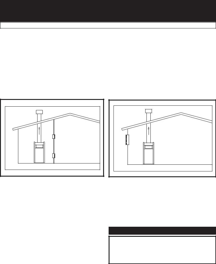
TABLE - B
Minimum Recommended Combustion
AIR SUPPLY TO MECHANICAL ROOM
Combustion Air Source
Btu/hr |
Outside Air* |
Outside Air* |
Inside Air |
Input |
2 - Openings |
1 - Opening |
2 - Openings |
|
|
|
|
1,500,000 |
375 in2 (2419 cm2) |
500 in2 (3226 cm2) |
1,500 in2 (9,677 cm2) |
|
|
|
|
1,700,000 |
425 in2 (2742 cm2) |
567 in2 (3658 cm2) |
1,700 in2 (10,968 cm2) |
|
|
|
|
2,000,000 |
500 in2 (3226 cm2) |
667 in2 (4303 cm2) |
2,000 in2 (12,903 cm2) |
|
|
|
|
*Outside air openings shall directly communicate with the outdoors. When combustion air is drawn from the outside through a duct, the net free area of each of the two openings must have twice (2 times) the free area required for Outside Air/2 Openings. The above requirements are for the boiler only, additional gas fired appliances in the equipment room will require an increase in the net free area to supply adequate combustion air for all appliances. Combustion air requirements are based on the latest edition of the National Fuel Gas Code, ANSI Z223.1, in Canada refer to the latest edition of CAN/CGA B149. Check all local code requirements for combustion air.
FIG. 7 Combustion Air from Interior Space |
FIG 8 Combustion Air from Outside - Single Opening |
3.If air is taken from another interior space, each of the two openings specified above should have a net free area of one square inch for each 1000 Btu (22 cm2 per kW) of input, but not less than 100 square inches (645 cm2).
4. If a |
single combustion air opening is |
provided |
to |
|||
bring |
combustion air in directly from the |
outdoors, |
||||
the |
opening must be sized |
based |
on |
a |
minimum |
|
free |
area of one square inch |
per |
3000 |
Btu (7 |
cm2 |
|
per kW). This opening must |
be located |
within |
12" |
|||
(30 cm) of the top of the enclosure. |
|
|
|
|
|
|
CAUTION
Under no circumstances should the mechanical room ever be under a negative pressure. Particular care should be taken where exhaust fans, attic fans, clothes dryers, compressors, air handling units, etc., may take away air from the unit.
6
All dimensions based on net free area in square inches. Metal louvers or screens reduce the free area of a combustion air opening a minimum of approximately 25%. Check with louver manufacturers for exact net free area of louvers. Where two openings are provided, one must be within 12" (30 cm) of the ceiling and one must be within 12" (30 cm) of the floor of the mechanical room. Each opening must have net free area as specified in Table - B. Single openings shall commence within 12" (30 cm) of the ceiling.
The combustion air supply must be completely free of any flammable vapors that may ignite or chemical fumes which may be corrosive to the appliance. Common corrosive chemical fumes which must be avoided are fluorocarbons and other halogenated compounds, most commonly present as refrigerants or solvents, such as Freon, trichlorethylene, perchlorethylene, chlorine, etc. These chemicals, when burned, form acids which quickly attack the heat exchanger finned tubes, headers, flue collectors, and the vent system. The result is improper combustion and a nonwarrantable, premature appliance failure.
These chemicals, when burned form acids which quickly attack the boiler tubes, tube sheets, flue collectors, and the appliance stack. The result is improper combustion and a non-warrantable, premature failure of the appliance.
EXHAUST FANS: Any fan or equipment which exhausts air from the equipment room may deplete the combustion air supply and/or cause a downdraft in the venting system. Spillage of flue products
from the venting system into an occupied living space can cause a very hazardous condition that must be immediately corrected. If a fan is used to supply combustion air to the equipment room, the installer must make sure that it does not cause drafts that could lead to nuisance operational problems with the appliance.
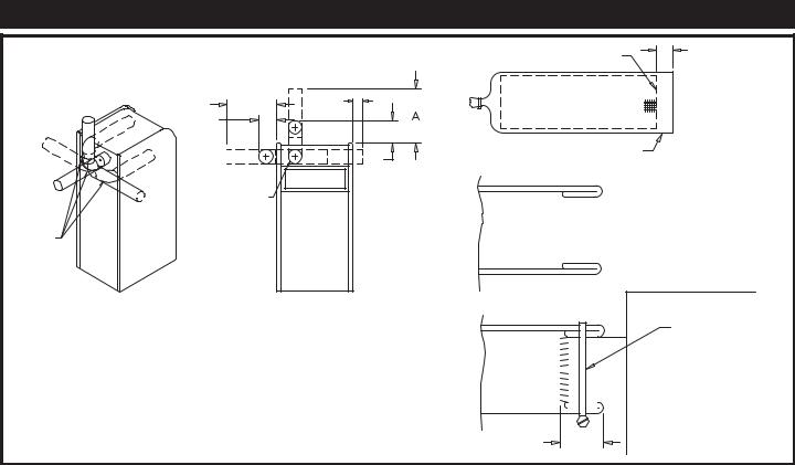
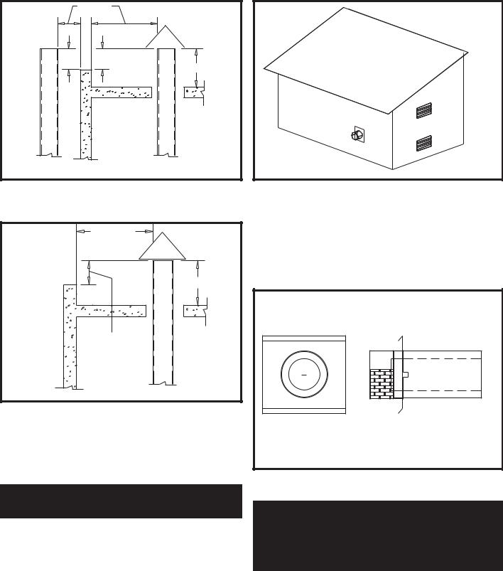
A construction air filter is installed on the appliance as shipped. The filter assembly is installed on the combustion air inlet located at the rear of the appliance. The filter assembly slips over the air inlet collar and is secured in place with the clamp provided with the filter. If limited space is available at the rear of the appliance, field supplied elbows may be used to mount the filter in the alternate positions shown in the illustration. This filter is For Temporary Use Only on an appliance that must be operated for temporary heat or hot water when a building is under construction. The filter will provide a temporary means to remove airborne dust, dirt and particulate matter generated by construction. The filter prevents airborne particulate contaminants from being drawn into the burner with the combustion air. The filter can be cleaned routinely during construction if necessary. Remove the filter to clean. Wash the filter with water. A flow of water from the inside to the outside should remove most particle matter. Allow the filter to dry before reinstalling. Unfiltered combustion air from a construction site can contain contaminants that will collect in the burner reducing the firing rate. A burner that becomes clogged with airborne particulate contaminants must be removed and cleaned to restore proper operation to the burner. Sustained operation of an appliance with a clogged burner may result in nuisance operational problems, bad combustion and non-warrantable component failures.
CONSTRUCTION AIR FILTER
2"
EDGE OF SCREEN
|
E |
C |
|
|
|
|
D |
|
|
|
MEDIA OVERLAP |
|
|
B |
|
CABINET AIR |
|
|
INLET OPENING |
|
|
|
FOLD OVERLAP AROUND |
ELBOW(S) |
|
EDGE OF SCREEN AS |
NOT |
|
SHOWN. |
PROVIDED |
|
|
|
|
|
REAR |
|
FRONT |
BAND CLAMP
|
|
|
|
|
|
|
|
|
|
|
|
|
|
|
MODEL |
A |
B |
C |
D |
E |
REAR |
|
|
|
|
|
|
||
2.0 |
19.750 |
12.250 |
4.875 |
9.000 |
15.000 |
24.000 |
|
|
|
|
|
|
|
|
1.7 |
19.250 |
10.750 |
4.375 |
7.500 |
14.500 |
24.000 |
|
|
|
|
|
|
|
PUSH FILTER ONTO AIR |
1.5 |
18.750 |
9.250 |
3.875 |
6.000 |
14.000 |
24.000 |
|
|
|
|
|
|
|
INLET AND FASTEN WITH |
|
|
|
|
|
|
|
|
|
|
|
|
|
|
CLAMP AS SHOWN. |
|
|
|
|
|
|
|
|
|
|
|
|
|
|
|
2"
FIG. 9 Construction Air Filter
7

The construction air filter MUST be removed from the appliance’s air inlet before the appliance is placed in normal operation. Once the construction air filter is removed, ensure that either the equipment room is supplied with combustion air from properly sized combustion and ventilation air openings or a combustion air duct from a Direct Vent or Intelli-Vent system is connected to the appliance. The optional Direct Vent and Intelli-Vent venting systems have specific requirements for a special combustion air duct from the outside that is directly connected to the appliance. See the requirements for this combustion air duct in the venting section for each specialized vent system.
CONSTRUCTION AIR FILTER KITS
TABLE - C
Input |
Construction |
Btu/hr |
Air Filter Kit |
|
|
1,500,000 |
KIT4000 |
________________________ |
________________________ |
1,700,000 |
KIT4001 |
________________________ |
________________________ |
2,000,000 |
KIT4002 |
|
|
VENTING
Vent System Options
This appliance has three venting system options. They are: (A) Category IV Venting system with vertical roof top termination or sidewall termination of the flue and combustion air supplied from the mechanical room. (B) Direct Vent with a Category IV flue and a separate combustion air pipe to the outdoors. The Direct Vent system terminates both the flue and air inlet in the same pressure zone. The flue outlet and combustion air intake may terminate on either the sidewall or with a rooftop termination.
(C) Intelli-Vent with a Category IV flue and a separate combustion air pipe to the outdoors.The Intelli-Vent system terminates the flue and the combustion air inlet pipe in different pressure zones. The Intelli-Vent system may terminate the flue on the roof top and combustion air intake on the sidewall, the flue on the sidewall and combustion air from the rooftop or the flue on the sidewall and combustion air from a different sidewall. All appliances are shipped from the factory equipped for Category IV venting. The optional Direct Vent and Intelli-Vent venting systems will require the installation of specific vent kits and venting materials. The following is a detailed explanation of the installation requirements for each venting system, components used and part numbers of vent kits for each model.
General
Vent installations for connection to gas vents or chimneys must be in accordance with Part 7, “Venting of Equipment,” of the latest edition of the National Fuel Gas Code, ANSI Z223.1, in Canada, the latest edition of CAN/CGA Standard B149 Installation Codes for Gas Burning Appliances and Equipment or applicable provisions of the local building codes.
Adequate combustion and ventilation air must be supplied to the equipment room in accordance with the latest edition of the National Fuel Gas Code, ANSI Z223.1, in Canada, the latest edition of CAN/CGA Standard B149 Installation Codes for Gas Burning Appliances and Equipment, or applicable provisions of the local building codes.
The distance of the vent terminal from adjacent buildings, windows that open and building openings MUST comply with the latest edition of the National Fuel Gas Code, ANSI Z223.1, in Canada, the latest edition of CAN/CGA Standard B149 Installation Code for Gas Burning Appliances and Equipment.
Vent connection is made directly to the flue outlet opening on the back of the unit. The connection from the appliance vent to the stack must be made as direct as possible.
IMPORTANT
Examine the venting system at least once a year. Check all joints and vent pipe connections for tightness. Also, check for corrosion or deterioration. Immediately correct any problems observed in the venting system.
TABLE - D
The Category IV Flue Pipe Sizes
Input Btu/hr |
|
Flue Size |
|
|
|
1,500,000 |
|
6" |
________________________ |
|
________________________ |
1,700,000 |
|
7" |
________________________ |
|
_______________________ |
2,000,000 |
|
8" |
|
|
|
8
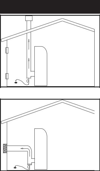
Category IV Venting
A CATEGORY IV POSITIVE PRESSURE VENTING SYSTEM
FIG. 10 Basic Category IV Venting - Vertical
The flue products in the vent system may be cooled below their dew point and form condensate in the flue. The materials used for a Category IV vent must be resistant to any corrosive damage from flue gas condensate. The flue from a Category IV vent system must have a condensate drain with provisions to properly collect and dispose of any condensate that may occur in the venting system.
Category IV Flue Pipe Materials
Select venting material from the following specified vent distributors:
Heat-Fab Inc. Saf-T CI Vent with AL29-4C stainless steel (Call 1-800-772-0739 for nearest distributor)
Protech Systems Inc. Fas N Seal Vent with AL29-4C stainless steel (Call 1-800-766-3473 for nearest distributor)
Z-Flex Z-Vent with AL29-4C stainless steel (Call 1-800-654-5600 for nearest distributor)
Or other listed Category IV vent systems suitable for a condensing, positive pressure gas fired appliance.
FIG. 11 Basic Category IV Venting - Horizontal
A Category IV venting system for the flue products is required on all models of this appliance. A Category IV venting system operates with a positive pressure in the vent. This positive pressure is generated by the internal combustion air blower which operates the combustion process and also exhausts the flue products from the building. The Category IV flue from this appliance can NOT be combined with the vent from any other appliance. The Category IV flues from multiple appliances can NOT be combined into a common vent. The Category IV flue from this appliance must be a dedicated stack. The flue from this Category IV appliance must have all vent joints and seams sealed gas-tight. A Category IV vent system has specific vent material and installation requirements.
Venting Guidelines for a Category IV Vent
The connection from the appliance vent to the stack or vent termination outside the building MUST be made with listed Category IV vent system and must be direct as possible with no reduction in diameter. The Category IV vent and accessories, such as firestop spacers, thimbles, caps, etc., MUST be installed in accordance with the vent manufacturers instructions. The vent connector and firestop must provide correct spacing to combustible surfaces and seal to the vent connector on the upper and lower sides of each floor or ceiling through which the vent connector passes.
In a typical installation, each appliance must have a dedicated Category IV flue with no other appliance interconnected to any part of the dedicated flue. Each appliance MUST connect to the dedicated flue stack using a properly sealed vent adapter provided by the vent manufacturer. The flues from multiple Intelli-Fin appliances may only be combined when using an engineered vent system incorporating an induced draft fan to ensure that flue products will be properly exhausted from the building at all times. Failure to use a properly sized induced draft fan on a combined vent installation may result in a hazardous condition where flue gases spill into an occupied living space. Consult the induced draft fan manufacturer to size the induced draft fan and to determine the diameter of the common vent pipe required for a combined vent installation.
9
Any vent materials specified must be listed by a nationally recognized test agency for use as a Category IV vent material.
The venting system must be planned so as to avoid possible contact with concealed plumbing or electrical wiring inside walls, floors or ceilings. Locate the appliance as close as possible to a chimney or gas vent.
There shall be no reductions in vent diameter.
Horizontal portions of the venting system shall be supported to prevent sagging. Horizontal runs should slope upwards not less than 1/4 inch per foot (21 mm/m) from the drain tee installed in the flue to the vertical portion of the flue or to the vent terminal on sidewall venting installations. This ensures proper removal of any condensate that may form in the flue. Follow the installation instructions from the vent material manufacturer.
Do not use an existing chimney as a raceway if another appliance or fireplace is vented through the chimney. The weight of the venting system must not rest on the unit. Adequate support of the venting system must be provided in compliance with local codes and other applicable codes. All connections should be secured and sealed per the vent manufacturers specifications.
Vent connectors serving appliances vented by natural draft shall not be connected to any portion of the Category IV positive pressure vent system used by this appliance. Connection of a negative draft flue into the positive pressure stack from this appliance may cause flue products to be discharged into an occupied living space causing serious health injury.
When a Category IV vent system is disconnected for any reason, the flue must be reassembled and resealed according to the vent manufacturer’s instructions.
The installed length of the Category IV flue from the appliance to the point of termination, outside of the building, must not exceed a maximum of 100 equivalent feet (30.5 m) in length. Subtract 5 feet (1.5 m) of equivalent length for each 90° elbow installed in the vent. Subtract 2 1/2 feet (0.7 m) of equivalent length for each 45° elbow installed in the vent.
The flue may terminate either vertically at the roof top or horizontally on a sidewall. See the information about the specific vent termination location for recommended location and clearances.
General Category IV Vent Termination Clearances
The vent cap should have a minimum clearance of 4 feet (1.2 m) horizontally from and in no case above or below, unless a 4 foot (1.2 m) horizontal distance is maintained from electric meters, gas meters, regulators and relief equipment.
The venting system shall terminate at least 3 feet (0.9 m) above any forced air inlet within 10 feet (3.05 m).
The venting system shall terminate at least 4 feet (1.2 m) below, 4 feet (1.2 m) horizontally from, or 1 foot (30 cm) above any door, window or gravity air inlet into any building.
Do not terminate the vent in a window well, stairwell, alcove, courtyard or other recessed area. The vent cannot terminate below grade. The bottom of the vent terminal shall be located at least 12 inches (30 cm) above grade and above normal snow levels.
To avoid a blocked flue condition, keep the vent cap clear of snow, ice, leaves, debris, etc.
Flue gases from this appliance may contain large amounts of water vapor that will form a white plume in winter. Plume could obstruct a window view.
Flue gas condensate can freeze on exterior surfaces or on the vent cap. Frozen condensate on the vent cap can result in a blocked flue condition. Flue gas condensate can cause discoloration of exterior building surfaces. Adjacent brick or masonry surfaces should be protected with a rust resistant sheet metal plate.
The manufacturer shall NOT be held liable for any personal injury or property damage due to ice formation or the dislodging of ice from the vent system or the vent termination.
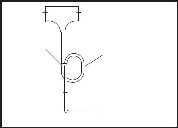
Drain Tee Installation
WIRE TIE
4" Ø
CIRCULAR TRAP
TO SUITABLE DRAIN
FIG. 12 Drain Tee
A drain tee MUST be installed in the Category IV vent pipe to collect and dispose of any condensate that may occur in the vent system. The drain tee should be installed at the point where the flue turns vertical for a roof top termination or as one of the first fittings in a horizontal flue that will terminate on a sidewall. Ensure that horizontal portions of the vent are properly sloped to allow condensate to be evacuated at the drain tee. See the typical vent installation drawings. Plastic drain tubing, sized per the vent manufacturer’s instructions, shall be provided as a drain line from
10
the tee. The drain tubing must have a trap provided by a 4" (10.2 cm)-diameter circular trap loop in the drain tubing. Prime the trap loop by pouring a small quantity of water into the drain hose before assembly to the vent. Secure the trap loop in position with nylon wire ties. Use caution not to collapse or restrict the condensate drain line with the nylon wire ties. The condensate drain must be routed to the condensate neutralization system or a suitable drain for disposal of condensate that may occur in the Category IV vent system. Refer to the condensate drain installation instructions as supplied by the manufacturer of the vent material. Ensure that the drain from the condensate tee is not exposed to freezing temperatures. See “Freeze Protection” for more information.
MASONRY CHIMNEY
INSTALLATIONS
A standard masonry chimney must NOT be used to vent the products of combustion from the flue of a Category IV, positive pressure appliance. If a masonry chimney is to be used, the chimney MUST use a sealed, metallic, corrosion resistant liner system to vent flue products from this high efficiency appliance. Sealed, metallic, corrosion resistant liner systems (single wall, double-wall, or flexible or rigid metallic liners) must be rated for use with a high efficiency Category IV, positive pressure vent system. Corrosion resistant chimney liner systems are typically made from a high grade of corrosion resistant stainless steel such as AL 29-4C. The corrosion resistant liner must be properly sized and fully sealed throughout the entire length if the flue is contained within the masonry chimney. Both the top and the bottom of the masonry chimney must be capped and sealed to provide a dead air space around the sealed corrosion resistant metallic liner. Consult with local code officials to determine code requirements or the advisability of using a masonry chimney with a sealed corrosion resistant liner system.
CAUTION
Venting of a high efficiency Category IV appliance into a masonry chimney without a sealed stainless steel liner can result in operational and safety problems. Any breaks, leaks or damage to the masonry flue/tile will allow spillage of the positive pressure flue products from the chimney. These flue products can easily escape into an occupied living space causing a health hazard. If there is any doubt about the condition of a masonry chimney, or its acceptability for use after insertion of a corrosion resistant liner system, consult with local code officials.
VERTICAL VENTING
TERMINATIONS
Follow all General Category IV Vent Termination Clearances.
|
10' OR LESS |
|
2' MIN |
RIDGE |
3' MIN |
|
|
|
CHIMNEY |
FIG. 13 Vent Termination from Peaked Roof - 10 Feet or Less from Ridge
MORE THAN 10' |
10' |
RIDGE |
2' MIN |
3' MIN |
CHIMNEY |
FIG. 14 Vent Termination from Peaked Roof - 10 Feet or More from Ridge
The vent terminal should be vertical and exhaust outside the building at least 2 feet (0.61 m) above the highest point of the roof within a 10 foot (3.05 m) radius of the termination.
The vertical termination must be a minimum of 3 feet (0.91 m) above the point of exit.
11
10' OR LESS
2' MIN |
2' MIN |
3' MIN
CHIMNEY WALL OR |
CHIMNEY |
PARAPET |
|
FIG. 15 Vent Termination from Flat Roof - 10 Feet or FIG. 17 Sidewall Venting Installation Less from Parapet Wall
10' OR MORE
3' MIN
|
NOTE: NO HEIGHT |
|
|
ABOVE PARAPET |
|
|
REQUIRED WHEN |
|
WALL OR |
DISTANCE FOR |
|
WALLS OR PARAPETS |
||
PARAPET |
||
IS MORE THAN 10'> |
||
|
CHIMNEY
FIG. 16 Vent Termination from Flat Roof - 10 Feet or More from Parapet Wall
The connection from the appliance flue outlet to the sidewall vent cap MUST be made with listed type Category IV vent materials and accessories. The installer must supply suitable vent pipe material. The sidewall vent cap is available from the appliance manufacturer as a vent kit.
A vertical termination less than 10 feet (3.05 m) from a parapet wall must be a minimum of 2 feet (0.61 m) higher than the parapet wall.
SIDEWALL VENTING
TERMINATIONS
This venting system uses the appliance’s internal combustion air blower to force the flue products out of a horizontally-terminated flue. This blower generates a positive pressure in the flue. Combustion air is drawn from the equipment room (see Combustion and Ventilation Air Requirements) unless the appliance is equipped with an optional Direct Vent or Intelli-Vent System.
FIG. 18 Sidewall Vent Cap
TABLE - E
Sidewall Vent Cap Kits
|
|
|
|
Sidewall Vent |
Input Btu/hr |
|
Flue Size |
|
Cap Kit |
|
|
|
|
|
1,500,000 |
|
6" |
|
SVK3026 |
________________ |
|
_____________ |
|
_________________ |
1,700,000 |
|
7" |
|
SVK3027 |
________________ |
|
_____________ |
|
_________________ |
2,000,000 |
|
8" |
|
SVK3028 |
|
|
|
|
|
The sidewall vent cap kit includes the wall penetration assembly and the discharge screen assembly. All required Category IV vent pipe and fittings must be purchased locally.
12
The installed sidewall vent cap assembly may be painted to match the exterior color. The opening through the wall for installation of the sidewall vent cap must provide an air space clearance of 2 inches (5.1 cm) around the flue pipe. The diameter of the opening for installation of the sidewall cap will be 4 inches (10.2 cm) larger (minimum) than the nominal diameter of the installed vent pipe to the sidewall cap.
The sidewall cap is installed from the outside and mounted to the wall with four screws or wall anchors. Seal under the screw heads with caulking. Install the screen assembly using the stainless steel screws provided in the kit. Install the Category IV vent pipe from the appliance to the vent cap. The installed vent pipe must protrude at least 2 inches (5.1 cm) into the screen area beyond the thimble portion of the sidewall cap assembly. See detailed instructions packed with the sidewall vent kit.
Follow all requirements in the General Category IV Venting sections for venting flue products to the outdoors. See the Combustion and Ventilation Air Requirements section to ensure that adequate combustion and ventilation air is supplied to the equipment room. All other general installation requirements must be followed.
LOCATION OF A SIDEWALL
VENT TERMINATION
Follow all General Category IV Vent Termination Clearances.
3' MIN. |
4' MIN. |
10' MIN. |
HORIZONTALLY |
FIG. 19 Sidewall Venting Installation with Clearances from Vent Cap
The vent cap shall terminate at least 3 feet (0.91 m) above any forced air inlet within 10 feet (3.05 m) horizontally.
The vent cap MUST NOT terminate below a forced air intake at any distance.
The vent shall terminate at least 4 feet (1.22 m) below, 4 feet (1.22 m) horizontally from or 1 foot (0.30 m) above and 2 feet (0.60 m) horizontally from any door, window or gravity air inlet to the building.
The sidewall vent termination must be at least 8 feet (2.4 m) horizontally from any combustion air intake located above the sidewall termination cap.
Do not terminate the vent in a window well, stairwell, alcove, courtyard or other recessed area. The vent cannot terminate below grade.
The vent shall not terminate directly above a public walkway due to the normal formation of water vapor in the combustion process. Horizontal terminations must not be located over areas of pedestrian or vehicular traffic.
The vent system shall terminate at least 1 foot (0.30 m) above grade, above normal snow levels and at least 7 feet (2.13 m) above grade when located adjacent to public walkways.
The vent terminal shall not be installed closer than 3 feet (0.91 m) from an inside corner of an L-shaped structure.
The vent cap should have a minimum clearance of 4 feet (1.22 m) horizontally from and in no case above or below, unless a 4-foot (1.22 m) horizontal distance is maintained from electric meters, gas meters, regulators and relief equipment.
Flue gas condensate can freeze on exterior walls or on the vent cap. Frozen condensate on the vent cap can result in a blocked flue condition. Some discoloration to exterior building surfaces can be expected. Adjacent brick or masonry surfaces should be protected with a rust resistant sheet metal plate.
The sidewall vent system must use the sidewall vent cap kit provided by the appliance manufacturer for installation on a sidewall termination.
The sidewall vent cap MUST be purchased as a kit from the appliance manufacturer to ensure proper operation. Locally purchased or fabricated sidewall vent caps should not be used.
DIRECT VENT AND
INTELLI-VENT SYSTEMS
Direct Vent and Intelli-Vent Systems are installed with a Category IV flue and a separate combustion air pipe to the outdoors. The Direct Vent System terminates both the flue and combustion air inlet in the same pressure zone. The Intelli-Vent System terminates the flue and combustion air inlet in different pressure zones. The flue outlet and combustion air intake may terminate with either a sidewall or a rooftop termination.
Follow all requirements in the General Category IV Venting sections for proper installation and venting of flue products vertically or horizontally to the outdoors. All other general installation requirements must be followed.
The Direct Vent and Intelli-Vent Systems require the installation of an additional pipe to supply combustion air from outdoors directly to the appliance.
13

In cold climates, the use of type “B” double wall vent pipe or an insulated single wall pipe for combustion air is recommended to help prevent moisture in the cool incoming air from condensing and leaking from the inlet pipe.
Termination point for the flue products must follow the clearance requirements in the Vertical or Horizontal Vent Termination sections of the Category IV Venting.
CAUTION
Appliances that are shut down or will not operate may experience freezing due to convective airflow in the air inlet pipe connected to the appliance.
TABLE - F
Direct Vent and Intelli-Vent Flue
and Air Inlet Pipe Sizes
|
|
|
Air Inlet |
Input Btu/hr |
|
Flue Size |
Pipe Size |
|
|
|
|
1,500,000 |
|
6" |
6" |
________________ |
|
______________ |
________________ |
1,700,000 |
|
7" |
7"* |
________________ |
|
_____________ |
________________ |
2,000,000 |
|
8" |
8" |
|
|
|
|
*Piping from the appliance to the air inlet cap may be either 7" or 8". An 8" diameter sidewall air inlet cap is provided in the vent kit.
Length of Air Inlet Pipe
The maximum total length of the sidewall or vertical roof top combustion air inlet pipe as installed from the appliance to the air inlet cap must not exceed 100 equivalent feet (30.5 m) in length. Subtract 5 feet (1.52 m) of equivalent length for each 90° elbow installed in the air inlet pipe system. Subtract 2 1/2 feet (0.7 m) of equivalent length for each 45° elbow installed in the air inlet pipe system.
Do not exceed limits for the combustion air inlet piping lengths.
Air Inlet Pipe Materials
The air inlet pipe(s) must be sealed. Choose acceptable combustion air inlet pipe materials from those specified in this section.
Select air inlet pipe material from the following specified materials:
•PVC, CPVC or ABS (6", 7"or 8" I.D.)*.
•Dryer Vent or Sealed Flexible Duct (not recommended for roof top air inlet).
•Galvanized steel vent pipe with joints and seams sealed as specified below.
•Type “B” double wall vent with joints and seams sealed as specified below.
* Plastic pipe may require an adapter (not provided) to transition between the air inlet connection on the appliance and the plastic air inlet pipe.
WARNING
Using vent or air intake materials other than those specified, failure to properly seal all seams and joints or failure to follow vent pipe manufacturer’s instructions can result in personal injury, death or property damage. Mixing of venting materials will void the warranty and certification of the appliance.
NOTE:
The use of double wall vent or insulated material for the combustion air inlet pipe is recommended in cold climates to prevent the condensation of airborne moisture in the incoming combustion air.
Sealing of Type “B” double wall vent material or galvanized vent pipe material used for air inlet pipe on a sidewall or vertical roof top Combustion Air Supply System.
a. |
Seal all joints and seams of |
the |
air inlet |
pipe |
|||
|
using either |
Aluminum |
Foil |
Duct |
Tape |
meeting |
|
|
UL Standard 723 or 181A-P |
or |
a high |
quality |
|||
|
UL Listed silicon sealant such as |
|
those |
||||
|
manufactured |
by Dow |
Corning |
or |
General |
||
|
Electric. |
|
|
|
|
|
|
b. |
Do not install seams of |
vent |
pipe |
on |
the |
||
|
bottom of horizontal runs. |
|
|
|
|
|
|
c.Secure all joints with a minimum of three sheet
metal |
screws |
or |
pop |
rivets. |
Apply |
aluminum |
||
foil duct tape |
or |
silicone sealant |
to |
all |
screws |
|||
or rivets installed in the vent pipe. |
|
|
|
|
||||
d. Ensure |
that |
the |
air |
inlet |
pipes |
are |
properly |
|
supported. |
|
|
|
|
|
|
|
|
The PVC, CPVC or ABS air inlet pipe should be cleaned and sealed with the pipe manufacturers recommended solvents and standard commercial pipe cement for the material used. The PVC, CPVC, ABS, Dryer Vent or Flex Duct air inlet pipe should use a silicone
14
sealant to ensure a proper seal at the appliance connection and the air inlet cap connection. Dryer vent or flex duct should use a screw type clamp to seal the vent to the appliance air inlet and the air inlet cap. Proper sealing of the air inlet pipe ensures that combustion air will be free of contaminants and supplied in proper volume.
When a sidewall or vertical roof top combustion air supply system is disconnected for any reason, the air inlet pipe must be resealed to ensure that combustion air will be free of contaminants and supplied in proper volume.
DANGER
Failure to properly seal all joints and seams as required in the air inlet piping may result in flue gas recirculation, spillage of flue products and carbon monoxide emissions causing severe personal injury or death.
Combined Combustion Air Inlet Points
The air inlet pipes from multiple appliances can be combined to a single common connection if the common air inlet pipe has a cross sectional area equal to or larger than the total area of all air inlet pipes connected to the common air inlet pipe. {Example: two 8" (20.3 cm) air inlet pipes [50.3 in2 (324.5 cm2) area each] have a total area of 100.6 in2 (645.2 cm2) requires a 12" (30.5 cm) [113.1 in2 (729.7 cm2] common air inlet pipe.} The air inlet point for multiple boiler air inlets must be provided with an exterior opening which has a free area equal to or greater than the total area of all air inlet pipes connected to the common air inlet. This exterior opening for combustion air must connect directly to the outdoors. The total length of the combined air inlet pipe must not exceed a maximum of 100 (30.5 m) equivalent feet. You must deduct the restriction in area provided by any screens, grills or louvers installed in the common air inlet point. These are common on the sidewall air inlet openings and some rooftop terminations. Screens, grills or louvers installed in the common air inlet can reduce the free area of the opening from 25% to 75% based on the materials used.
3' |
|
|
|
|
|
|
12" |
|
|
|
|
|
|
FIG. 20 |
Vertical |
Direct |
Vent |
Installation |
with |
Rooftop |
Combustion Air Inlet
Follow all requirements in the General Category IV Venting sections for proper installation and of venting flue products vertically to the outdoors. All other general installation requirements must be followed.
The Direct Vent system requires the installation of an additional pipe to supply combustion air from outdoors directly to the appliance. The air inlet pipe must use one of the specified materials.
The maximum installed length of the air inlet pipe from the appliance to the air inlet cap is 100 equivalent feet (30.48 m) in length. The maximum installed length of the flue pipe from the appliance to the termination cap is 100 equivalent feet (30.48 m) in length. Subtract 5 feet (1.52 m) of equivalent length for each 90° elbow installed in either the flue pipe or the air inlet pipe.
Termination point for the flue products must follow the clearance requirements in the Vertical Vent Termination sections of the
Category IV Venting.
VERTICAL DIRECT VENT SYSTEMS
A Vertical Direct Vent System is installed with a Category IV flue and a separate combustion air pipe to the outdoors. The Direct Vent system terminates both the flue and air inlet in the same pressure zone. The flue outlet and combustion air intake must both terminate on the rooftop.
15
VERTICAL COMBUSTION AIR INLET |
Incorrect installation and/or location of the air inlet cap can allow |
||||||||||||||||||||||||||||
the discharge of flue products to be drawn into the combustion |
|||||||||||||||||||||||||||||
|
|
|
|
|
|
|
|
|
process on the heater. This can result in incomplete combustion |
||||||||||||||||||||
|
|
|
|
|
|
|
|
|
|||||||||||||||||||||
|
|
|
|
|
|
|
|
|
and potentially hazardous levels of carbon monoxide in the flue |
||||||||||||||||||||
|
|
|
|
|
|
|
|
|
products. This will cause operational problems with the heater and |
||||||||||||||||||||
|
|
|
|
|
|
|
|
|
possible spillage of flue products that can cause personal injury, |
||||||||||||||||||||
|
|
|
|
|
|
|
|
|
death or property damage. |
||||||||||||||||||||
|
|
|
|
|
|
|
|
|
|||||||||||||||||||||
|
|
|
|
|
|
|
|
|
Multiple Vertical Direct Vent Installations |
||||||||||||||||||||
|
|
|
|
|
|
|
|
|
|||||||||||||||||||||
|
|
|
|
|
|
|
|
|
|||||||||||||||||||||
|
|
|
|
|
|
|
|
|
|||||||||||||||||||||
|
|
|
|
|
|
|
|
|
|
|
|
|
|
|
|
|
|
|
|
|
|
|
|
|
|
|
|
|
|
|
|
|
|
|
|
|
|
|
|
|
|
|
|
|
|
|
|
|
|
|
|
|
|
|
|
|
|
|
|
|
|
|
|
|
|
|
|
|
|
|
|
|
|
|
|
|
|
|
|
|
|
|
|
|
|
|
|
|
|
|
|
|
|
|
|
|
|
|
|
|
|
|
|
|
|
|
|
|
|
|
|
|
|
|
|
|
|
|
|
|
|
|
|
|
|
|
|
|
|
|
|
|
|
|
|
|
|
|
|
|
|
|
|
|
|
|
|
|
|
|
|
|
|
|
|
|
|
|
|
|
|
|
|
|
|
|
|
|
|
|
|
|
|
|
|
|
|
|
|
|
|
|
|
|
|
|
|
|
|
|
|
|
|
|
|
|
|
|
|
|
|
|
|
|
|
|
|
|
|
|
|
|
|
|
|
|
|
|
|
|
|
|
|
|
|
|
|
|
|
|
|
|
|
|
|
|
|
|
|
|
|
|
|
|
|
|
|
|
|
|
|
|
|
|
|
|
|
|
|
|
|
|
|
|
|
|
|
|
|
|
|
|
|
|
|
|
|
|
|
|
|
|
|
|
|
|
|
|
|
|
|
|
|
|
|
|
|
|
|
|
|
|
|
|
|
|
|
|
|
|
|
|
|
|
|
|
|
|
|
|
|
|
|
|
|
|
|
|
|
|
|
|
|
|
|
|
|
|
|
|
|
|
|
|
|
|
|
|
|
|
|
|
|
|
|
|
|
|
|
|
|
|
|
|
|
|
|
|
|
|
|
|
|
|
|
|
|
|
|
|
|
|
|
|
|
|
|
|
|
FIG. 21 Air Inlet Cap for Rooftop Termination
The air inlet cap for the vertical roof top air inlet is assembled from components purchased locally. The air inlet cap consist of two 90° elbows installed at the point of termination for the air inlet pipe. The first 90° elbow is installed on the rooftop at the highest vertical point of the air inlet pipe and turned horizontal, the second 90° elbow is installed on the horizontal outlet of the first elbow and turned down. A 90° elbow and a 90° street elbow may be used to make this assembly. If a straight piece of pipe is used between the two elbows, it should not exceed 6" (150 mm) in length. The termination elbow on the air inlet must be located a minimum of 12" (0.30 m) above the roof or above normal levels of snow accumulation.
The point of termination for the combustion air inlet cap MUST be at least 3 feet (0.91 m) below the point of flue gas termination (vent cap) if it is located within a 10 foot (3.05 m) radius of the flue outlet. Use care to ensure that the 90° elbow assembly is properly installed on the air inlet pipe.
The combustion air inlet cap must not be installed closer than 10 feet (3.05 m) from an inside corner of an L-shaped structure.
The termination point of the combustion air inlet cap must be installed at least one foot (0.30 m) above the rooftop and above normal snow levels.
The combustion air cap assembly used MUST adequately protect the combustion air inlet from wind and weather.
The combustion air cap and flue gas outlet MUST be located on the same roof top surface and in the same pressure zone.
Combustion air supplied from outdoors must be free of contaminants (see Combustion and Ventilation Air). To prevent recirculation of flue products in to the combustion air inlet, follow all instructions in this section.
FIG. 22 Multiple Vertical Direct Vent Installations
The combustion air inlet caps for multiple appliance installations must maintain the minimum 3 foot (0.91 m) clearance below the closest vertical flue outlet if within 10 feet (3.05 m). Multiple flue outlet caps may be installed side by side and multiple air inlet caps may be installed side by side but the air inlet must always be at least 3 feet (0.91 m) below the closest flue outlet if the outlet is within 10 feet (3.05 m). All clearance and installation requirements in this section and the applicable portions of the general Category IV venting section must be maintained on multiple appliance installations.
HORIZONTAL DIRECT VENT
For venting flue products horizontally to the outdoors, follow all requirements in the installation instructions for sidewall venting. Termination point for the flue products must follow the clearance requirements in the Sidewall Vent Termination section of Category IV Venting.
AHorizontal Direct Vent System is installed with a Category IV flue and a separate combustion air pipe to the outdoors. The Direct Vent system terminates both the flue and air inlet in the same pressure zone. The flue outlet and combustion air intake must both terminate on the same sidewall.
Follow all requirements in the General Category IV Venting sections for proper installation and of venting flue products to the outdoors with a sidewall termination. All other general installation requirements must be followed.
16
The Direct Vent system requires the installation of an additional pipe to supply combustion air from outdoors directly to the appliance. The air inlet pipe must use one of the specified materials.
The maximum installed length of the air inlet pipe from the appliance to the air inlet cap is 100 equivalent feet (30.48 m) in length. The maximum installed length of the flue pipe from the appliance to the termination cap is 100 equivalent feet (30.48 m) in length. Subtract 5 feet (1.52 m) of equivalent length for each 90° elbow installed in either the flue pipe or the air inlet pipe. Subtract 2 1/2 feet (0.7 m) of equivalent length for each 45° elbow installed in either the flue or the air inlet pipe.
Termination point for the flue products must follow the clearance requirements in the Sidewall Venting Termination sections of the
Category IV Venting.
FIG. 23 Horizontal Direct Vent Installations with Sidewall Combustion Air Inlet
SIDEWALL COMBUSTION
AIR INLET
Horizontal Direct Vent systems installed with sidewall terminations for both combustion air and flue products must purchase the termination caps from the appliance manufacturer. The sidewall air inlet cap and sidewall vent cap for flue products are available as a vent kit.
FIG. 24 Sidewall Vent Cap
The part numbers for the required sidewall air inlet cap kit are listed by unit size. The manufacturer, in accordance with CSA requirements, must furnish the sidewall air inlet cap. Each kit includes the special combustion air inlet cap for installation on an exterior sidewall. The sidewall air inlet cap supplied in the kit is sized to provide combustion air for a single appliance only.
TABLE - G
|
|
Flue |
|
Air Inlet |
|
Sidewall Air |
Input |
|
Cap |
|
Cap |
|
Inlet & Flue |
Btu/hr |
|
Size |
|
Size |
|
Cap Kit |
|
|
|
|
|
|
|
1,500,000 |
|
6" |
|
6" |
|
HDK3018 |
___________ |
|
__________ |
|
__________ |
|
______________ |
1,700,000 |
|
7" |
|
8"* |
|
HDK3019 |
___________ |
|
__________ |
|
__________ |
|
______________ |
2,000,000 |
|
8" |
|
8" |
|
HDK3020 |
|
|
|
|
|
|
|
*Piping from the appliance to the air inlet cap may be either 7" or 8" connecting to an 8" sidewall cap provided in the kit.
Location of a Sidewall Air Inlet Cap
Incorrect installation and/or location of the air inlet cap can allow the discharge of flue products to be drawn into the combustion process on the heater. This can result in incomplete combustion and potentially hazardous levels of carbon monoxide in the flue products. This will cause operational problems with the heater and possible spillage of flue products that can cause personal injury, death or property damage.
The termination point of the sidewall air inlet must be installed a minimum of 12 inches (0.30 m) above ground level and above normal levels of snow accumulation.
The point of termination for the sidewall combustion air inlet cap MUST be located a minimum of 3 feet (0.92 m) horizontally and 12 inches (0.30 m) below the point of flue gas termination (vent cap) if it is located within a 10 foot (3.05 m) radius of the flue outlet.
17
FIG. 25 Air Inlet Cap for Sidewall Termination
The sidewall combustion air inlet cap MUST NOT be installed above the sidewall flue outlet if it is located within a 10 foot (3.05 m) radius of the flue outlet.
The sidewall combustion air inlet cap must not be installed closer than 10 feet (3.05 m) from an inside corner of an L-shaped structure.
The sidewall combustion air cap assembly used MUST adequately protect the combustion air inlet from wind and weather.
The sidewall combustion air inlet cap and flue gas outlet MUST be located on the same sidewall surface and in the same pressure zone.
Combustion air supplied from outdoors must be free of contaminants (see Combustion and Ventilation Air). To prevent recirculation of flue products into the combustion air inlet, follow all instructions in this section.
Multiple Horizontal Direct Vent Installations
FLUE OUTLETS |
3' HORIZONTALLY |
1' BELOW FLUE |
AIR INLET CAP |
FIG. 26 Multiple Horizontal Direct Vent Caps Installed on a Sidewall
The combustion air inlet caps for multiple appliance installations must maintain the same minimum clearance from the closest vent cap installed within a 10 foot (3.05 m) radius of the point of flue gas termination as specified in single appliance installations. Multiple flue outlet caps may be installed side by side and multiple air inlet caps may be installed side by side but the minimum clearance of 3 feet (0.91 m) horizontal radius and 12 inches (0.30 m) below the closest flue outlet to the air inlet cap must be maintained. All clearance and installation requirements in this section and the applicable portions of the general Category IV venting section must be maintained on multiple appliance installations.
INTELLI-VENT SYSTEMS
An Intelli-Vent system is a Category IV flue installed with a separate combustion air pipe to the outdoors. The Intelli-Vent system terminates the flue and the combustion air inlet pipe in different pressure zones. The Intelli-Vent system may terminate the flue and combustion air in any one of three configurations.
These are:
(1) |
The |
flue |
on |
the |
roof |
top |
and |
combustion |
air intake |
|
|
on the sidewall; |
|
|
|
|
|
|
|||
(2) |
The |
flue |
on |
the |
sidewall |
and |
combustion |
air |
from |
|
|
the rooftop; |
|
|
|
|
|
|
|
||
(3) |
The |
flue |
on |
the |
sidewall and the combustion air on |
|||||
|
a sidewall other |
than |
the |
sidewall where |
the |
flue |
||||
|
is located. |
|
|
|
|
|
|
|
|
|
All appliances are shipped from the factory equipped for Category IV venting system. The optional Intelli-Vent systems require the installation of specific venting materials that are purchased locally. Sidewall termination caps for flue products and combustion air must be purchased from the manufacturer. The sidewall caps for combustion air and flue products are available as vent kits. The following is a detailed explanation of the installation requirements for each venting system, components used and part numbers of vent kits for each model.
Follow all requirements in the General Category IV Venting sections for proper installation and of venting flue products to the outdoors with either a rooftop or a sidewall termination. All other general installation requirements must be followed.
The Intelli-Vent System requires the installation of an additional pipe to supply combustion air from outdoors directly to the appliance. The air inlet pipe must use one of the specified materials.
18
Combined Air Inlet Points
The air inlet pipes from multiple appliances installed with an Intelli-Vent system can be combined to a single common connection based on the cross sectional area of the common pipe as defined in the Direct Vent basic information section.
Maximum Length of an Intelli-Vent System
The maximum installed length of the air inlet pipe from the appliance to the air inlet cap is 100 equivalent feet (30.5 m) in length. The maximum installed length of the flue pipe from the appliance to the termination cap is 100 equivalent feet (30.5 m) in length. Subtract 5 feet (1.52 m) of equivalent length for each 90° elbow installed in either the flue pipe or the air inlet pipe.
Subtract 2 1/2 feet (0.7 m) of equivalent length for each 45° elbow installed in either the flue pipe or the air inlet pipe.
VERTICAL INTELLI-VENT WITH SIDEWALL COMBUSTION AIR
FIG. 27 Vertical Intelli-Vent Installation - Sidewall Combustion
Air Inlet
Intelli-Vent systems are installed with a Category IV flue and a separate combustion air pipe to the outdoors. The Vertical Intelli-Vent system terminates the flue at the rooftop and air inlet at the sidewall. The flue outlet and combustion air intake terminates in different pressure zones.
Follow all requirements in the General Category IV Venting sections for proper installation and venting of flue products vertically to the outdoors. All other general installation requirements must be followed.
The Intelli-Vent system requires the installation of an additional pipe to supply combustion air from outdoors directly to the appliance.
Termination point for the flue products must follow the clearance requirements in the Vertical Vent Termination section of the
Category IV Venting.
CAUTION
Appliances that are shut down or will not operate may experience freezing due to convective airflow in the air inlet pipe connected to the appliance.
SIDEWALL COMBUSTION
AIR INLET
FIG. 28 Air Inlet Cap for Sidewall Termination
The air inlet cap for the sidewall air inlet must be purchased from the appliance manufacturer.
The part numbers for the required sidewall air inlet cap kit are listed by unit size. The appliance manufacturer, in accordance with CSA requirements, must furnish the sidewall air inlet cap. Each kit includes the special combustion air inlet cap for installation on an exterior sidewall.
TABLE - H
|
|
|
|
Air Inlet |
|
Sidewall |
Input |
|
Flue |
|
Pipe |
|
Air Inlet |
Btu/hr |
|
Size |
|
Size |
|
Cap Kit |
|
|
|
|
|
|
|
1,500,000 |
|
6" |
|
6" |
|
SAK3000 |
___________ |
|
___________ |
|
___________ |
|
___________ |
1,700,000 |
|
7" |
|
7"* |
|
SAK3001 |
___________ |
|
___________ |
|
___________ |
|
___________ |
2,000,000 |
|
8" |
|
8" |
|
SAK3002 |
|
|
|
|
|
|
|
*Piping from the appliance to the air inlet cap may be either 7" or 8" connecting to an 8" sidewall cap provided in the kit.
19
Location of a Sidewall Air Inlet Cap
Installation, location and clearance requirements for the sidewall air inlet cap in an Intelli-Vent application are the same as the installation, location and clearance requirements for the sidewall air inlet cap in the Horizontal Direct Vent section of the venting instructions.
The sidewall combustion air inlet cap and the rooftop flue gas outlet are located in different pressure zones in an Intelli-Vent system.
Combustion air supplied from outdoors must be free of contaminants (see Combustion and Ventilation Air). To prevent recirculation of flue products in to the combustion air inlet, follow all instructions in this section.
Incorrect installation and/or location of the air inlet cap can allow the discharge of flue products to be drawn into the combustion process on the heater. This can result in incomplete combustion and potentially hazardous levels of carbon monoxide in the flue products. This will cause operational problems with the heater and possible spillage of flue products that can cause personal injury, death or property damage.
HORIZONTAL INTELLI-VENT WITH VERTICAL COMBUSTION AIR
The Intelli-Vent system requires the installation of an additional pipe to supply combustion air from outdoors directly to the appliance.
In cold climates, the use of type “B” double wall vent pipe or an insulated single wall pipe is recommended to prevent moisture in the cool incoming air from condensing and leaking from the inlet pipe.
Termination point for the flue products must follow the clearance requirements in the Horizontal Sidewall Vent Termination section of the Category IV Venting.
CAUTION
Appliances that are shut down or will not operate may experience freezing due to convective airflow in the air inlet pipe connected to the appliance.
The flue and air inlet duct sizes for a Horizontal Intelli-Vent Installation with Rooftop Combustion Air Inlet are listed by unit size. The sidewall vent cap must be purchased from the appliance manufacturer as a vent kit.
Intelli-Vent systems are installed with a Category IV flue and a separate combustion air pipe to the outdoors. The Horizontal Intelli-Vent system terminates the flue at the sidewall and air inlet at the rooftop. The flue outlet and combustion air intake terminate in different pressure zones.
12" MIN. |
FIG. 29 Horizontal Intelli-Vent Installation - Rooftop
Combustion Air Inlet
TABLE - I
|
|
|
|
Air Inlet |
|
Sidewall |
Input |
|
Flue |
|
Pipe |
|
Vent |
Btu/hr |
|
Size |
|
Size |
|
Cap Kit |
|
|
|
|
|
|
|
1,500,000 |
|
6" |
|
|
|
|
|
|
6" |
|
SVK3026 |
||
___________ |
|
___________ |
|
___________ |
|
____________ |
1,700,000 |
|
7" |
|
7"* |
|
SVK3027 |
___________ |
|
___________ |
|
___________ |
|
____________ |
2,000,000 |
|
8" |
|
8" |
|
SVK3028 |
|
|
|
|
|
|
|
*Piping from the appliance to the air inlet cap may be either 7" or 8" connecting to an 8" sidewall cap provided in the kit.
Follow all requirements in the General Category IV Venting sections for proper installation and of venting flue products horizontally to the outdoors. All other general installation requirements must be followed.
20
VERTICAL COMBUSTION |
|
HORIZONTAL INTELLI-VENT |
AIR INLET |
|
WITH SIDEWALL COMBUSTION AIR |
|
|
|
FIG. 30 Air Inlet Cap for Rooftop Termination
The air inlet cap for the vertical roof top air inlet is assembled from components purchased locally. The air inlet cap consist of two 90° elbows installed at the point of termination for the air inlet pipe. The first 90° elbow is installed on the rooftop at the highest vertical point of the air inlet pipe and turned horizontal, the second 90° elbow is installed on the horizontal outlet of the first elbow and turned down. A 90° elbow and a 90° street elbow may be used to make this assembly. If a straight piece of pipe is used between the two elbows, it should not exceed 6 inches (150 mm) in length. The termination elbow on the air inlet must be located a minimum of 12 inches (0.30 m) above the roof or above normal levels of snow accumulation.
Location of a Rooftop Air Inlet Cap
Incorrect installation and/or location of the air inlet cap can allow the discharge of flue products to be drawn into the combustion process on the heater. This can result in incomplete combustion and potentially hazardous levels of carbon monoxide in the flue products. This will cause operational problems with the heater and possible spillage of flue products that can cause personal injury, death or property damage.
Installation, location and clearance requirements for the rooftop air inlet cap in an Intelli-Vent application are the same as the installation, location and clearance requirements for the rooftop air inlet cap in the Vertical Direct Vent section of the venting instructions.
The rooftop combustion air inlet cap and the sidewall flue gas outlet are located in different pressure zones in an Intelli-Vent system.
Combustion air supplied from outdoors must be free of contaminants (see Combustion and Ventilation Air). To prevent recirculation of flue products in to the combustion air inlet, follow all instructions in this section and related Direct Vent sections.
Intelli-Vent systems are installed with a Category IV flue and a separate combustion air pipe to the outdoors. The Horizontal Intelli-Vent system terminates the flue at the sidewall and the combustion air on a sidewall other than the sidewall where the flue is located. The sidewall flue outlet and sidewall combustion air intake must terminate in different pressure zones.
Follow all requirements in the General Category IV Venting sections for proper installation and of venting flue products horizontally to the outdoors. All other general installation requirements must be followed.
The Intelli-Vent System requires the installation of an additional pipe to supply combustion air from outdoors directly to the appliance.
FIG. 31 Horizontal Intelli-Fin Installation with Sidewall Combustion Air in a Different Pressure Zone
In cold climates, the use of type “B” double wall vent pipe or an insulated single wall pipe is recommended to help prevent moisture in the cool incoming air from condensing and leaking from the inlet pipe.
Termination point for the flue products must follow the clearance requirements in the Horizontal Sidewall Vent Termination section of the Category IV Venting.
21
CAUTION
Appliances that are shut down or will not operate may experience freezing due to convective airflow in the air inlet pipe connected to the appliance.
The flue and air inlet duct sizes for a Horizontal Intelli-Vent Installation with Sidewall Combustion Air Inlet are listed by unit size.
SIDEWALL COMBUSTION
AIR INLET
Intelli-Vent systems installed with sidewall terminations for both combustion air and flue products must purchase the termination caps from the appliance manufacturer. The sidewall air inlet cap and sidewall vent cap for flue products are available as a vent kit.
FIG. 32 Sidewall Vent Cap
The part numbers for the required sidewall air inlet and flue cap kit are listed by unit size. The manufacturer, in accordance with CSA requirements, must furnish both the sidewall air inlet and flue cap. Each kit includes the both the special combustion air inlet cap and the sidewall flue cap for installation on an exterior sidewall. The sidewall air inlet cap supplied in the kit is sized to provide combustion air for a single appliance only.
TABLE - J
|
|
Flue |
|
Air Inlet |
|
Sidewall Air |
Input |
|
Cap |
|
Cap |
|
Inlet & Flue |
Btu/hr |
|
Size |
|
Size |
|
Cap Kit |
|
|
|
|
|
|
|
1,500,000 |
|
6" |
|
6" |
|
|
|
|
|
HDK3018 |
|||
___________ |
|
_______ |
|
_______ |
|
________________ |
1,700,000 |
|
7" |
|
8"* |
|
HDK3019 |
___________ |
|
_______ |
|
_______ |
|
________________ |
2,000,000 |
|
8" |
|
8" |
|
HDK3020 |
|
|
|
|
|
|
|
*Piping from the appliance to the air inlet cap may be either 7" or 8" connecting to an 8" sidewall cap provided in the kit.
Location of a Sidewall Air Inlet Cap
Installation, location and clearance requirements for the sidewall air inlet cap in an Intelli-Vent application are the same as the installation, location and clearance requirements for the sidewall air inlet cap in the Horizontal Direct Vent section of the venting instructions.
FIG. 33 Air Inlet Cap for Sidewall Termination
The sidewall combustion air inlet cap and the rooftop flue gas outlet are located in different pressure zones in an Intelli-Vent system.
Combustion air supplied from outdoors must be free of contaminants (see Combustion and Ventilation Air). To prevent recirculation of flue products in to the combustion air inlet, follow all instructions in this and related sections.
Incorrect installation and/or location of the air inlet cap can allow the discharge of flue products to be drawn into the combustion process on the heater. This can result in incomplete combustion and potentially hazardous levels of carbon monoxide in the flue products. This will cause operational problems with the heater and possible spillage of flue products that can cause personal injury, death or property damage.
22

GAS SUPPLY |
|
GAS PRESSURE TEST |
|
|
|
Verify that the appliance is supplied with the type gas specified on the rating plate. Consult factory for installations at altitude.
INLET PRESSURE: Measured at the inlet pressure tap on the appliance gas manifold. The pressure tap is located upstream of the redundant gas valve and down stream of the field installed gas cock.
TABLE - K
Inlet Gas Pressure
|
|
Natural |
|
L. P. |
|
|
Gas |
|
Gas |
|
|
|
|
|
Max. (Inches-Water Column) |
|
10.5" w.c. |
|
13.0" w.c. |
______________________________ |
|
________ |
|
_________ |
Min. (Inches-Water Column) |
|
4.0" w.c. |
|
4.0" w.c. |
|
|
|
|
|
Maximum inlet gas pressure must not exceed the value specified. Minimum value listed is for the purposes of input adjustment.
MANIFOLD PRESSURE: Manifold pressure is a differential pressure measurement made between the high and low pressure taps at the gas orifice and the pressure in the transition chamber where the gas is supplied to the inlet of the combustion air blower. All manifold gas pressures are noted at full firing rate. The controls on this appliance may fire the burner from 25% up to 100% of rated input, based on system demand. Manifold gas pressure will be reduced as burner input is reduced. All reference gas pressure measurements must be made at 100% of rated burner input. The gas manifold pressure is pre-set at the factory by the ratio gas valve. Adjustment of manifold pressure is not normally required for proper operation. The adjustment point on the ratio gas valve is set at the factory. DO NOT attempt to adjust the settings on the ratio gas valve. Improper adjustment of the ratio gas valve may cause incomplete combustion or non-warrantable burner damage.
TABLE - L
Nominal Manifold Pressure
Settings at Full Fire
|
|
Natural |
L. P. |
|
Input Btu/hr |
|
Gas |
Gas |
|
|
|
|
|
|
1,500,000 - 2,000,000 |
|
3.5" w.c. |
|
3.5" w.c. |
|
|
|
|
|
1. The |
appliance |
must be disconnected |
from the gas |
||||
supply |
piping |
system |
during any |
pressure |
testing |
||
of |
that |
system |
at a |
test pressure |
in |
excess |
of 1/2 |
PSIG (3.5kPa). |
|
|
|
|
|
||
2.The appliance must be isolated from the gas supply
piping |
system |
by |
closing a |
manual |
shutoff |
valve |
|||||
during |
any pressure |
testing |
of |
the |
gas |
supply |
|||||
piping |
system |
at |
test |
pressures |
equal |
to |
or |
less |
|||
than 1/2 PSIG (3.5kPa). |
|
|
|
|
|
|
|
|
|||
3. The |
appliance |
and |
its |
gas |
connection |
must |
be |
||||
leak-tested before placing it in operation. |
|
|
|
|
|||||||
GAS CONNECTION
1. |
Safe operation of unit requires properly |
sized gas |
|
supply piping. See gas line sizing data. |
|
2. |
Gas pipe size may be larger than |
appliance |
|
connection. |
|
3.Installation of a union at the appliance gas line
|
connection is required for ease |
of |
service |
and |
||||||
|
removal of the gas train. |
|
|
|
|
|
|
|||
4. |
Install |
a |
manual |
main |
gas shutoff |
valve, |
outside |
of |
||
|
the appliance gas connection and |
before |
|
the |
gas |
|||||
|
valve, when local codes require. |
|
|
|
|
|
||||
5. |
A trap |
(drip leg) |
MUST be provided in |
the |
inlet of |
|||||
|
the gas connection to the appliance. |
|
|
|
|
|
||||
6. |
The diaphragm gas valve has a |
bleed |
port |
that |
||||||
|
requires |
|
venting |
to |
atmosphere, |
outside |
the |
|||
|
building. |
|
|
|
|
|
|
|
|
|
7. |
Optional gas controls may require |
routing |
of bleeds |
|||||||
|
and vents |
to the atmosphere, outside |
the |
building |
||||||
|
when required by local codes. |
|
|
|
|
|
||||
23

TABLE - M
Recommended Gas Pipe Size
Single Appliance Installations
|
|
|
Distance from Meter |
|
|
|
Btu/hr |
|
|
|
|
|
|
0 - 50 ft. |
51 - 100 ft. |
101 - 200 ft. |
|
201 - 300 ft. |
301 - 500 ft. |
|
|
|
|
|
|
|
|
1,500,000 |
2" |
2 1/2" |
3" |
|
|
3 1/2" |
|
|
|
|
|
|
|
1,700,000 |
2 1/2" |
2 1/2" |
3" |
|
3" |
3 1/2" |
|
|
|
|
|
|
|
2,000,000 |
2 1/2" |
3" |
3" |
|
3 1/2" |
4" |
|
|
|
|
|
|
|
For each elbow or tee, add equivalent straight pipe to total length from TABLE - O.
TABLE - N
Multiple Appliance Installations Gas Pipe Size Chart
Nominal |
|
|
|
|
|
Length of Pipe in Straight Feet |
|
|
|
|
|||||
|
|
|
|
|
|
|
|
|
|
|
|
|
|
||
Iron Pipe Size, |
|
|
|
|
|
|
|
|
|
|
|
|
|
|
|
Inches |
|
|
|
|
|
|
|
|
|
|
|
|
|
|
|
|
10 |
20 |
30 |
40 |
50 |
60 |
70 |
80 |
90 |
100 |
125 |
150 |
175 |
200 |
|
|
|
||||||||||||||
|
|
|
|
|
|
|
|
|
|
|
|
|
|
|
|
3/4 |
369 |
256 |
205 |
174 |
155 |
141 |
128 |
121 |
113 |
106 |
95 |
86 |
79 |
74 |
|
|
1 |
697 |
477 |
384 |
328 |
292 |
267 |
246 |
256 |
210 |
200 |
179 |
164 |
149 |
138 |
|
|
|
|
|
|
|
|
|
|
|
|
|
|
|
|
1 |
1/4 |
1,400 |
974 |
789 |
677 |
595 |
543 |
502 |
472 |
441 |
410 |
369 |
333 |
308 |
287 |
1 |
1/2 |
2,150 |
1,500 |
1,210 |
1,020 |
923 |
830 |
769 |
707 |
666 |
636 |
564 |
513 |
472 |
441 |
|
2 |
4,100 |
2,820 |
2,260 |
1,950 |
1,720 |
1,560 |
1,440 |
1,330 |
1,250 |
1,180 |
1,100 |
974 |
871 |
820 |
2 1/2 |
6,460 |
4,460 |
3,610 |
3,100 |
2,720 |
2,460 |
2,310 |
2,100 |
2,000 |
1,900 |
1,700 |
1,540 |
1,400 |
1,300 |
|
|
3 |
11,200 |
7,900 |
6,400 |
5,400 |
4,870 |
4,410 |
4,000 |
3,800 |
3,540 |
3,300 |
3,000 |
2,720 |
2,500 |
2,340 |
|
|
|
|
|
|
|
|
|
|
|
|
|
|
|
|
|
4 |
23,500 |
16,100 |
13,100 |
11,100 |
10,000 |
9,000 |
8,300 |
7,690 |
7,380 |
6,870 |
6,150 |
5,640 |
5,130 |
4,720 |
Maximum Capacity of Pipe in Thousands of Btu’s per hour for gas pressures of 14 Inches Water Column (0.5 PSIG) or less and a pressure drop of 0.5 Inch Water Column (Based on NAT GAS, 1025 Btu’s per Cubic Foot of Gas and 0.60 Specific Gravity).
TABLE - O
Fittings to Equivalent Straight Pipe
Diameter Pipe Fitting (inches)
3/4" |
|
1" |
1 1/4" |
|
1 1/2" |
|
2" |
|
3" |
|
4" |
|
5" |
|||
|
|
|
|
|
|
|
|
|
|
|
|
|
|
|
|
|
|
|
|
|
|
|
|
|
|
|
|
|
|
|
|
|
|
|
|
Equivalent Length of Straight Pipe (feet) |
|
|
|
|||||||||||
|
|
|
|
|
|
|
|
|
|
|
|
|
|
|
||
|
|
|
|
|
|
|
|
|
|
|
|
|
|
|
||
2' |
|
2' |
|
3' |
|
|
4' |
|
5' |
|
10' |
|
14' |
|
20' |
|
|
|
|
|
|
|
|
|
|
|
|
|
|
|
|
|
|
24
 Loading...