


Service Manual
Models: ER152, ER202,
ER252, ER302, and ER402
WARNING This manual must only be used by a qualified heating installer / service technician. Read all instructions, including this manual and the EnergyRite Installation and Operation Manual, before installing. Perform steps in the order given. Failure to comply could result in severe personal injury, death, or substantial property damage.
Save this manual for future reference.
Service Manual
Contents
Contents . . . . . . . . . . . . . . . . . . . . . . . . . . . . . . . . . . . . . . . . . . . . . . . . . . . . . . . 2 Hazard definitions . . . . . . . . . . . . . . . . . . . . . . . . . . . . . . . . . . . . . . . . . . . . . . . . 2 Please read before proceeding . . . . . . . . . . . . . . . . . . . . . . . . . . . . . . . . . . . . . 3 What is in this manual? . . . . . . . . . . . . . . . . . . . . . . . . . . . . . . . . . . . . . . . . . . . 5 1. Service . . . . . . . . . . . . . . . . . . . . . . . . . . . . . . . . . . . . . . . . . . . . . . . . . . . . . 6
General Operation . . . . . . . . . . . . . . . . . . . . . . . . . . . . . . . . . . . . . . . . . . 9 Access Setup Menu . . . . . . . . . . . . . . . . . . . . . . . . . . . . . . . . . . . . . . . . . 10 Access Service Menu . . . . . . . . . . . . . . . . . . . . . . . . . . . . . . . . . . . . . . . 11 2. Maintenance . . . . . . . . . . . . . . . . . . . . . . . . . . . . . . . . . . . . . . . . . . . . . . . . . 13 Burner removal and cleaning . . . . . . . . . . . . . . . . . . . . . . . . . . . . . . . . . 15 Heat exchanger cleaning . . . . . . . . . . . . . . . . . . . . . . . . . . . . . . . . . . . . . 17 Combustion air shutter adjustment . . . . . . . . . . . . . . . . . . . . . . . . . . . . 18 Facts about water chemistry . . . . . . . . . . . . . . . . . . . . . . . . . . . . . . . . . 20 Heat exchanger inspection . . . . . . . . . . . . . . . . . . . . . . . . . . . . . . . . . . . 21 Prevention of freezing . . . . . . . . . . . . . . . . . . . . . . . . . . . . . . . . . . . . . . . 21 Winterizing . . . . . . . . . . . . . . . . . . . . . . . . . . . . . . . . . . . . . . . . . . . . . 21
3. Troubleshooting . . . . . . . . . . . . . . . . . . . . . . . . . . . . . . . . . . . . . . . . . . . . . . 22 Troubleshooting Chart - No Display . . . . . . . . . . . . . . . . . . . . . . . . . . . . 22 Checking temperature sensors . . . . . . . . . . . . . . . . . . . . . . . . . . . . . . . . 23 Troubleshooting Chart - Noisy System . . . . . . . . . . . . . . . . . . . . . . . . . . 24 Troubleshooting Chart - Fault Messages . . . . . . . . . . . . . . . . . . . . . . . . 25 Gas Manifold Pressure Adjustment Procedure . . . . . . . . . . . . . . . . . . . . 28 Checking Gas Supply Pressure . . . . . . . . . . . . . . . . . . . . . . . . . . . . . . . . 30
Hazard definitions
The following defined terms are used throughout this manual to bring attention to the presence of hazards of various risk levels or to important information concerning the life of the product.
DANGER
WARNING
CAUTION
CAUTION
NOTICE
2
DANGER indicates an imminently hazardous situation which, if not avoided, will result in death or serious injury.
WARNING indicates a potentially hazardous situation which, if not avoided, could result in death or serious injury.
CAUTION indicates a potentially hazardous situation which, if not avoided, may result in minor or moderate injury.
CAUTION used without the safety alert symbol indicates a potentially hazardous situation which, if not avoided, may result in property damage.
NOTICE indicates special instructions on installation, operation, or maintenance that are important but not related to personal injury or property damage.
Service Manual
Please read before proceeding
WARNING |
Installer |
– Read |
all |
instructions, |
NOTICE |
When calling or writing |
about the pool |
||
|
including this manual and the |
|
heater – Please have the pool heater model |
||||||
|
EnergyRite |
Installation |
and Operation |
|
and serial number from the pool heater |
||||
|
Manual, before installing. Perform steps |
|
rating plate. |
|
|
|
|||
|
in the order given. |
|
|
|
Consider piping and installation when |
||||
|
|
|
|
|
|
||||
|
User – This manual is for use only by a |
|
determining pool heater location (see the |
||||||
|
qualified |
heating |
installer/service |
|
EnergyRite |
Installation |
and |
Operation |
|
|
technician. |
Refer |
to the EnergyRite |
|
Manual). |
|
|
|
|
|
User’s Information |
Manual for your |
|
Any claims |
for damage |
or |
shortage in |
||
|
reference. |
|
|
|
|
||||
|
|
|
|
|
shipment must be filed immediately against |
||||
|
|
|
|
|
|
||||
|
Have this pool heater serviced/inspected |
|
the transportation company by the |
||||||
|
by a qualified service technician at least |
|
consignee. |
|
|
|
|||
|
annually. |
|
|
|
|
|
|
|
|
Failure to comply with the above could result in severe personal injury, death or substantial property damage.
Handling ceramic fiber materials
REMOVAL OF COMBUSTION CHAMBER LINING
WARNING The combustion chamber insulation in this product contains ceramic fiber material. Ceramic fibers can be converted to cristobalite in very high temperature applications. The International Agency for Research on Cancer (IARC) has concluded, “Crystalline silica inhaled in the form of quartz or cristobalite from occupational sources is carcinogenic to humans (Group 1).”:
Avoid breathing dust and contact with skin and eyes.
•Use NIOSH certified dust respirator (N95). This type of respirator is based on the OSHA requirements for cristobalite at the time this document was written. Other types of respirators may be needed depending on the job site conditions. Current NIOSH recommendations can be found on the NIOSH website at http://www.cdc.gov/niosh/homepage.html. NIOSH approved respirators, manufacturers, and phone numbers are also listed on this website.
•Wear long-sleeved, loose fitting clothing, gloves, and eye protection.
Apply enough water to the combustion chamber lining to prevent airborne dust.
Remove the combustion chamber lining from the pool heater and place it in a plastic bag for disposal.
Wash potentially contaminated clothes separately from other clothing. Rinse clothes washer thoroughly.
NIOSH stated First Aid.
Eye: Irrigate immediately.
Breathing: Fresh air.
3

Service Manual
Please read before proceeding
When servicing pool heater –
•To avoid electric shock, disconnect electrical supply before performing maintenance.
•To avoid severe burns, allow the pool heater to cool before performing maintenance.
Pool heater operation –
•Do not block flow of combustion or ventilation air to the pool heater.
•Should overheating occur or gas supply fail to shut off, do not turn off or disconnect electrical supply to circulator. Instead, shut off the gas supply at a location external to the appliance.
•Do not use this pool heater if any part has been under water. The possible damage to a flooded appliance can be extensive and present numerous safety hazards. Any appliance that has been under water must be replaced.
Pool heater water –
•Do not use petroleum-based cleaning or sealing compounds in the pool heater system. Gaskets and seals in the system may be damaged. This can result in substantial property damage.
•Do not use “homemade cures” or “pool heater patent medicines”. Serious damage to the pool heater, personnel, and/or property may result.
4

What is in this manual?
Service
The EnergyRite display
• Display panel readout, buttons and their functions
Control module inputs
• Control module inputs and options
Control module outputs
• Control module outputs and options
General
•How the pool heater operates
•How the control module operates
Control panel menu access
• Accessing service and setup mode and locating menus
Service Manual
Maintenance
•Service and maintenance schedules
•Inspect pool heater area and pool heater interior
•Check all piping for leaks
•Check air openings
•Flue vent system and air piping
•Check water system
•Check pool heater relief valve (if applicable)
•Inspect ignition electrode
•Check ignition ground wiring
•Check all pool heater wiring
•Check control settings
•Perform start-up and checks
•Check burner flame
•Check flame signal
•General maintenance
•Cleaning heat exchanger
Troubleshooting
•Troubleshooting table - No display
•Checking temperature sensors
•Sensor table
•Troubleshooting table - Fault messages displayed on pool heater interface
•Gas manifold pressure adjustment procedure
•Checking gas supply pressure
5

Service Manual
1Service
The EnergyRite display
6
Service Manual
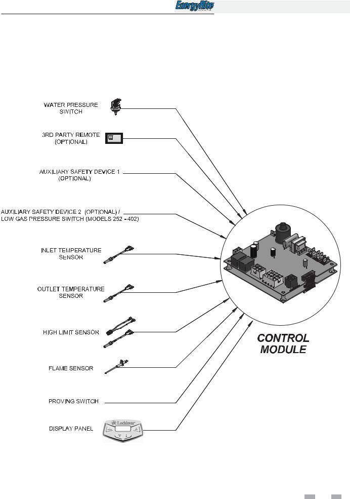
1Service (continued)
Control inputs
7
Service Manual
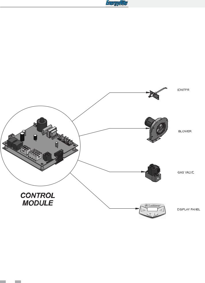
1Service
Control outputs
8

1Service (continued)
General Operation
How the pool heater operates
The EnergyRite uses a copper finned tube heat exchanger and an electronic control module. The blower provides both primary and secondary air to the burners and forces the flue products out of the combustion chamber and into the vent system. The combination gas valve both regulates the manifold pressure and provides gas to the manifold, which then supplies the burners. The control and gas supply system is a fixed rate and only performs ON/OFF operation.
How the control module operates
The EnergyRite control monitors the inlet sensor which is indicative of pool/spa water temperature. The control will begin an ignition sequence when the water temperature has dropped below the set point minus the differential. It will also monitor all safety circuits and will terminate or prevent an ignition cycle if a safety circuit is open. In addition, the control will monitor the outlet temperature and will terminate a call for heat if the outlet temperature gets too high.
Service Manual
9
Service Manual
1Service
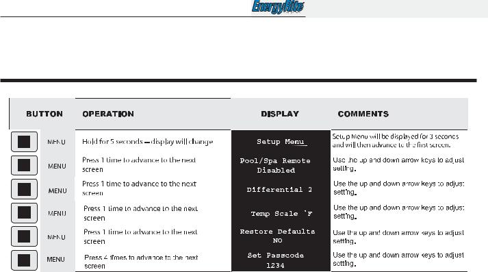
Access setup menu
Table 1A Use this procedure to access the Setup Menu from the display panel
The pool heater will continue to operate while the Setup Menu is being accessed. To adjust settings, press the MENU button until the desired screen is displayed. Use the UP and DOWN buttons to adjust the setting within the screen. By pressing the MENU or POOL/SPA button the new setting will be stored into memory and the next screen will be displayed.
When adjusting “set passcode” the 4 individual digits can be adjusted. The digit on the far left will be active first. Use the UP and DOWN buttons to adjust the digit. Once the MENU button is pushed, that digit is stored into memory and the next digit to the right is active. Continue on until all digits have been adjusted.
After 1 minute of inactivity, all settings are stored and the control will exit the Setup Menu. To manually exit the Setup Menu at any time, press the POOL/SPA button once.
Setup menu descriptions
Pool/spa remote
This setting allows the user to enable or disable the remote capability of switching from pool to spa. The default setting is disable.
There are three (3) options under this menu: T Stat, Switch, and Disable.
T Stat - Select this option when the heater is used in conjunction with a two wire remote system which includes its own thermostat. This option will automatically set the set point to 104° (max.) and all messages on the display will become generic (i.e. no references to pool or spa). Where there is no call for heat the pool heater will remain in Standby Mode.
 10
10 
Switch - Select this option when the heater is used in conjunction with a three wire remote system, also known as a three-way switch. The remote will control the pool heater if it is in Pool, Spa, or Standby Mode and will utilize the thermostat on the heater. When there is no call for Pool or Spa Mode, the pool heater will remain in Standby Mode.
When in T Stat or Switch Mode, the user can turn the control “OFF” by pressing the POOL/SPA button on the display.
Disable - This is the default setting. When this option is selected the heater will ignore all inputs on R, Ws, and Wp. The heater will not recognize any of the remotes.
For additional wiring instructions consult the third party remote manufacturer along with the EnergyRite Installation and Operation Manual.
Differential
This setting allows the user to choose how far below set point the water temperature must drop before the control will initiate a call for heat. The range of adjustment is from 1°F to 15°F. The default setting is 2°F.
Temperature scale
This setting allows the user the choice of showing the displayed temperature in degrees Fahrenheit or degrees Celsius. The default setting is Fahrenheit.
Restore defaults
This setting allows the user to restore the factory default settings for the Setup Menu and temperature settings.
Set passcode
This setting allows the user to set a personal passcode that would be required to lock and unlock the keypad. See Keypad Lockout on page 12 of this manual. The default passcode is 1234.
 Loading...