


Lochinvar 1002, 1302, 1501, 2001, 1701 User Manual
...PBX-PFX-I&O Rev E
Installation & Operation Manual
Models: 502, 752, 1002, 1302,
1501, 1701, and 2001
Up To 5:1 Turndown
WARNING:
This manual supplies information for the installation, operation, and servicing of the appliance. It is strongly recommended that this manual and the Power-fin Service Manual be reviewed completely before proceeding with an installation. Perform steps in the order given. Failure to comply could result in severe personal injury, death, or substantial property damage.
Save this manual for future reference.
|
Contents |
|
Hazard definitions . . . . . . . . . . . . . . . . . . . . . . . . . . . . . . . . . . . . . . . . . |
. . . . . . . . 2 |
|
Please read before proceeding . . . . . . . . . . . . . . . . . . . . . . . . . . . . . . . . |
. . . . . . . 3 |
|
Ratings . . . . . . . . . . . . . . . . . . . . . . . . . . . . . . . . . . . . . . . . . . . . . . . . . . . |
. . . . . . . 5 |
|
The Power-fin -- How it works . . . . . . . . . . . . . . . . . . . . . . . . . . . . . . . . . |
. . . . . . . 6 |
|
1. |
Determine unit location . . . . . . . . . . . . . . . . . . . . . . . . . . . . . . . . . . . |
. . . . . . . 9 |
2. |
Venting - Before You Begin . . . . . . . . . . . . . . . . . . . . . . . . . . . . . . . . |
. . . . . . . 13 |
|
Condensing vent options: CAT II & IV . . . . . . . . . . . . . . . . . . . . |
. . . . . . . 15 |
|
Non-Condensing vent options: CAT I . . . . . . . . . . . . . . . . . . . . . |
. . . . . . . 19 |
|
Common venting CAT I & II . . . . . . . . . . . . . . . . . . . . . . . . . . . . . |
. . . . . . . 21 |
|
CAT I, II, & IV general venting information . . . . . . . . . . . . . . . . . |
. . . . . . . 22 |
|
CAT IV specific venting information . . . . . . . . . . . . . . . . . . . . . . |
. . . . . . . 22 |
|
CAT II & IV drain tee requirements . . . . . . . . . . . . . . . . . . . . . . . |
. . . . . . . 23 |
|
CAT I specific venting information . . . . . . . . . . . . . . . . . . . . . . . |
. . . . . . . 23 |
|
Vertical air inlet . . . . . . . . . . . . . . . . . . . . . . . . . . . . . . . . . . . . . . |
. . . . . . . 24 |
|
Horizontal air inlet . . . . . . . . . . . . . . . . . . . . . . . . . . . . . . . . . . . . |
. . . . . . . 25 |
|
Vertical vent termination clearances . . . . . . . . . . . . . . . . . . . . . |
. . . . . . . 27 |
|
Sidewall vent termination clearances . . . . . . . . . . . . . . . . . . . . . |
. . . . . . . 29 |
3. |
Gas connections . . . . . . . . . . . . . . . . . . . . . . . . . . . . . . . . . . . . . . . . . |
. . . . . . . 31 |
4. |
Water connections . . . . . . . . . . . . . . . . . . . . . . . . . . . . . . . . . . . . . . . |
. . . . . . . 35 |
5. |
Electrical connections . . . . . . . . . . . . . . . . . . . . . . . . . . . . . . . . . . . . |
. . . . . . . 44 |
6. |
Condensate disposal . . . . . . . . . . . . . . . . . . . . . . . . . . . . . . . . . . . . . |
. . . . . . . 49 |
7. |
Start-up . . . . . . . . . . . . . . . . . . . . . . . . . . . . . . . . . . . . . . . . . . . . . . . . |
. . . . . . . 50 |
8. |
Operating information . . . . . . . . . . . . . . . . . . . . . . . . . . . . . . . . . . . . |
. . . . . . . 56 |
9. |
Domestic water heaters . . . . . . . . . . . . . . . . . . . . . . . . . . . . . . . . . . . |
. . . . . . . 68 |
10. Maintenance . . . . . . . . . . . . . . . . . . . . . . . . . . . . . . . . . . . . . . . . . . . . |
. . . . . . . 72 |
|
11. Wiring diagram . . . . . . . . . . . . . . . . . . . . . . . . . . . . . . . . . . . . . . . . . |
. . . . . . . 78 |
|
12. Ladder diagram . . . . . . . . . . . . . . . . . . . . . . . . . . . . . . . . . . . . . . . . . |
. . . . . . . 79 |
|
Revision Notes . . . . . . . . . . . . . . . . . . . . . . . . . . . . . . . . . . . . . . . . . . . . . |
Back Cover |
|
Hazard definitions
The following defined terms are used throughout this manual to bring attention to the presence of hazards of various risk levels or to important information concerning the life of the product.
DANGER
WARNING
CAUTION
CAUTION
NOTICE
DANGER indicates an imminently hazardous situation which, if not avoided, will result in death or serious injury.
WARNING indicates a potentially hazardous situation which, if not avoided, could result in death or serious injury.
CAUTION indicates a potentially hazardous situation which, if not avoided, may result in minor or moderate injury.
CAUTION used without the safety alert symbol indicates a potentially hazardous situation which, if not avoided, may result in property damage.
NOTICE indicates special instructions on installation, operation, or maintenance that are important but not related to personal injury or property damage.
2
Please read before proceeding
NOTICE |
This is a gas appliance and should be installed |
|
by a licensed electrician and/or certified gas |
||
|
||
|
supplier. Service must be performed by a |
|
|
qualified service installer, service agency or the |
|
|
gas supplier. |
WARNING If the information in these instructions is not followed exactly, a fire or explosion may result
causing property damage, personal injury, or death.
This appliance MUST NOT be installed in any location where gasoline or flammable vapors are likely to be present, unless the installation is such to eliminate the probable ignition of gasoline or flammable vapors.
What to do if you smell gas –
• Do not try to light any appliance.
• Do not touch any electric switch; do not use any phone in your building.
•Immediately call your gas supplier from a neighbors phone. Follow the gas supplier’s instructions.
•If you cannot reach your gas supplier, call the fire department.
Installation and service must be performed by a qualified installer, service agency, or the gas supplier.
Warranty –
Factory warranty (shipped with unit) does not apply to units improperly installed or improperly operated.
Experience has shown that improper installation or system design, rather than faulty equipment, is the cause of most operating problems.
1.Excessive water hardness causing a lime/scale build-up in the copper tube is not the fault of the equipment and is not covered under the manufacturer’s warranty (see
Water Treatment and Water Chemistry).
2.Excessive pitting and erosion on the inside of the copper tube may be caused by too much water velocity through the tubes and is not covered by the manufacturer’s warranty (see Boiler Flow Rates and Temperature Rise for flow requirements).
Installation & Operation Manual
WARNING Improper installation, adjustment, alteration, service or maintenance can cause injury or property damage. Refer to this manual for assistance or additional information, consult a qualified installer, service agency or the gas supplier.
Checking equipment –
Upon receiving equipment, check for signs of shipping damage. Pay particular attention to parts accompanying the appliances which may show signs of being hit or otherwise being mishandled. Verify total number of pieces shown on packing slip with those actually received. In case there is damage or a shortage, immediately notify the carrier.
Do not use this appliance if any part has been under water. The possible damage to a flooded appliance can be extensive and present numerous safety hazards. Any appliance that has been under water must be replaced.
Owner warning –
The information contained in this manual is intended for use by qualified professional installers, service technicians, or gas suppliers. Consult your local expert for proper installation or service procedures.
NOTICE |
Consult and follow all local Building and |
|
Fire Regulations and other Safety Codes |
||
|
||
|
||
|
that apply to this installation. Consult |
|
|
local gas utility company to authorize and |
|
|
inspect all gas and flue connections. |
A gas appliance that draws combustion air from the equipment room where it is installed must have a supply of fresh air circulating around it during burner operation for proper gas combustion and proper venting.
WARNING Should overheating occur or the gas supply fail to shut off, do not turn off or
disconnect the electrical supply to the pump. Instead, shut off the gas supply at a location external to the appliance.
Prevention of freezing –
Heat exchangers and headers damaged by freezing are not covered by warranty.
See Section 7, Startup - Freeze Protection for more information.
3

Installation & Operation Manual
Please read before proceeding
WARNING To minimize the possibility of serious personal injury, fire, or damage to your appliance, never violate the following safety rules:
1.Boilers and water heaters are heat producing appliances. To avoid damage or injury, do not store materials against the appliance or the vent-air intake system. Use proper care to avoid unnecessary contact (especially children) with the appliance and vent-air intake components.
2.Never cover your appliance, lean anything against it, store trash or debris near it, stand on it or in any way block the flow of fresh air to your appliance.
3.UNDER NO CIRCUMSTANCES must flammable materials such as gasoline or paint thinner be used or stored in the vicinity of this appliance, vent-air intake system or any location from which fumes could reach the appliance or vent-air intake system.
Codes –
The equipment shall be installed in accordance with those installation regulations in force in the local area where the installation is to be made. These shall be carefully followed in all cases. Authorities having jurisdiction shall be consulted before installations are made. In the absence of such requirements, the installation shall conform to the latest edition of the National Fuel Gas Code, ANSI Z223.1. Where required by the authority having jurisdiction, the installation must conform to American Society of Mechanical Engineers Safety Code for Controls and Safety Devices for Automatically Fired Boilers, ASME CSD-1. All boilers conform to the latest edition of the ASME Boiler and Pressure Vessel Code, Section IV. Where required by the authority having jurisdiction, the installation must comply with the Canadian Gas Association Code, CAN/CGA-B149.1 and/or B149.2 and/or local codes. This appliance meets the safe lighting performance criteria with the gas manifold and control assembly provided, as specified in the ANSI standards for gasfired hot water boilers, ANSI Z21.13 and gas water heaters, ANSI Z21.10.3.
4
Installation & Operation Manual
Ratings
Power-fin
I=B=R Rating
Model Number |
|
|
|
|
|
Net |
|
Input |
|
Gross |
I=B=R |
||
B = Boiler |
|
|
||||
|
MBH |
|
Output |
Ratings |
||
F = Water Heater |
|
|
||||
|
|
|
|
MBH |
Water, |
|
|
|
(Note 4) |
|
|||
Note: Change “N” to |
|
|
|
MBH |
||
|
|
|
|
|
||
“L” for L.P. gas models. |
Min |
|
Max |
|
(Note 1) |
(Note 2) |
|
|
|
||||
|
|
|
|
|
|
|
P(B/F)N0502-M9 |
100 |
|
500 |
425 |
370 |
|
|
|
|
|
|
|
|
P(B/F)N0752-M9 |
150 |
|
750 |
637 |
554 |
|
|
|
|
|
|
|
|
P(B/F)N1002-M9 |
200 |
|
1000 |
850 |
739 |
|
|
|
|
|
|
|
|
P(B/F)N1302-M9 |
260 |
|
1300 |
1105 |
961 |
|
|
|
|
|
|
|
|
|
|
|
|
|
|
|
P(B/F)N0502-F9 |
N/A |
|
500 |
425 |
370 |
|
|
|
|
|
|
|
|
P(B/F)N0752-F9 |
N/A |
|
750 |
637 |
554 |
|
|
|
|
|
|
|
|
P(B/F)N1002-F9 |
N/A |
|
1000 |
850 |
739 |
|
|
|
|
|
|
|
|
P(B/F)N1302-F9 |
N/A |
|
1300 |
1105 |
961 |
|
|
|
|
|
|
|
|
|
|
|
|
|
|
|
P(B/F)N1501-M9 |
300 |
|
1500 |
1275 |
1109 |
|
|
|
|
|
|
|
|
P(B/F)N1701-M9 |
340 |
|
1700 |
1445 |
1257 |
|
|
|
|
|
|
|
|
P(B/F)N2001-M9 |
440 |
|
2000 |
1700 |
1478 |
|
|
|
|
|
|
|
|
|
|
|
|
|
|
|
P(B/F)N1501-B9 |
900 |
|
1500 |
1260 |
1096 |
|
|
|
|
|
|
|
|
P(B/F)N1701-B9 |
1020 |
|
1700 |
1428 |
1242 |
|
|
|
|
|
|
|
|
P(B/F)N2001-B9 |
1200 |
|
2000 |
1680 |
1461 |
|
|
|
|
|
|
|
|
Other Specifications
Appliance |
|
|
Air / Vent |
|
Water |
Water |
Gas |
||
Sizes |
||||
Content |
Connections |
Connections |
||
|
||||
Gallons |
|
|
|
|
|
|
|
(Note 3) |
|
|
|
|
|
|
3.50 |
2.5" |
1" |
5" - 4" |
|
|
|
|
|
|
4.00 |
2.5" |
1 1/4" |
5" - 5" |
|
|
|
|
|
|
4.50 |
2.5" |
1 1/4" |
6" - 6" |
|
|
|
|
|
|
5.00 |
2.5" |
1 1/4" |
6" - 8" |
|
|
|
|
|
|
|
|
|
|
|
3.50 |
2.5" |
1" |
5" - 7" |
|
|
|
|
|
|
4.00 |
2.5" |
1 1/4" |
5" - 9" |
|
|
|
|
|
|
4.50 |
2.5" |
1 1/4" |
6" - 10" |
|
|
|
|
|
|
5.00 |
2.5" |
1 1/4" |
6" - 12" |
|
|
|
|
|
|
|
|
|
|
|
5.50 |
2.5" |
1 1/2" |
6" - 6" |
|
|
|
|
|
|
5.75 |
2.5" |
1 1/2" |
7" - 7" |
|
|
|
|
|
|
6.13 |
2.5" |
1 1/2" |
8" - 8" |
|
|
|
|
|
|
|
|
|
|
|
5.50 |
2.5" |
1 1/2" |
6" - 12" |
|
|
|
|
|
|
5.75 |
2.5" |
1 1/2" |
7" - 14" |
|
|
|
|
|
|
6.13 |
2.5" |
1 1/2" |
8" - 14" |
|
|
|
|
|
NOTICE Maximum allowed working pressure is located on the rating plate.
Notes:
1.The ratings are based on standard test procedures prescribed by the United States Department of Energy.
2.Net I=B=R ratings are based on net installed radiation of sufficient quantity for the requirements of the building and nothing need be added for normal piping and pickup. Ratings are based on a piping and pickup allowance of 1.15.
3.Power-fins require special gas venting. Use only the vent materials and methods specified in the Power-fin Installation and Operation Manual.
4.The Power-fin is equipped for operation up to 2000 feet, and including up to 4000 feet, with no field adjustments. The appliance output ratings up to 4000 feet shall be reduced by 4% for each 1000 feet above sea level. For operation above 4000 feet, consult the factory.
5

Installation & Operation Manual
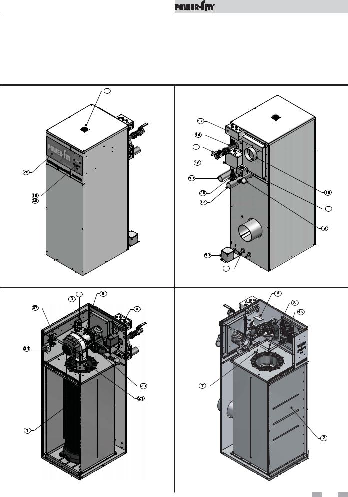
The Power-fin - How it works...
1. Heat exchanger |
15. SMART SYSTEM Control Module |
The heat exchanger allows system water to flow through specially designed tubes for maximum heat transfer. The glass lined headers and copper finned tubing are encased in a jacket that contains the combustion process.
2.Heat exchanger access cover
The heat exchanger access cover is a stainless steel door which allows access for service, maintenance, and removal of the heat exchanger from inside the combustion chamber.
3.Blower
The blower pulls in air and gas through the venturi (see item 5) and injects the fuel/air mixture into the burner, where they burn inside the combustion chamber.
4.Gas valve
The gas valve allows the proper amount of gas to pass into the burner for combustion. The gas valve on the Power-fin works under a negative pressure so gas should only be pulled through the valve when the blower is in operation.
5.Venturi
The venturi attaches to the inlet (or suction) side of the blower and generates the negative pressure needed by the gas valve.
6.Flue sensor (not shown)
The flue sensor is mounted in the exhaust collar of the unit and monitors the flue gas temperature. If the temperature in the stack exceeds the maximum temperature the unit will shut down to prevent a hazardous condition. In Category I models the flue sensor helps to control the amount of modulation to prevent condensation in the stack.
7.Outlet temperature sensor
This sensor monitors the outlet water temperature. If selected as the controlling sensor, the appliance will maintain set point by adjusting the firing rate of the unit according to this sensor.
8.Inlet temperature sensor
This sensor monitors inlet water temperature. If selected as the controlling sensor, the appliance will maintain set point by adjusting the firing rate of the unit according to this sensor.
9.Temperature and pressure gauge
The temperature and pressure gauge monitors the outlet temperature of the appliance as well as the system water pressure.
10.Electronic display
The electronic display consists of 7 buttons and a dual line 32-character liquid crystal display used to monitor the operation of the heater as well as enter and view the programming of the main control board.
11.Burner (not shown)
The burner is made of a woven fabric over steel screen construction. The burner uses pre-mixed air and gas and provides a wide range of firing rates.
12.Water outlet (system supply)
The water outlet is a 2 1/2" pipe connection that supplies water to the system with connections for a flow switch (see #28), a relief valve (see #25), and a temperature and pressure gauge (boilers only) (see #9).
13.Water inlet (system return)
The water inlet is a 2 1/2" pipe connection that receives water from the system and delivers it to the heat exchanger.
14.Gas connection pipe
The gas pipe connection on this appliance is 1", 1 1/4", or 1 1/2" NPT. To deliver the correct amount of gas volume to the appliance it may be necessary to have a larger gas line reduced to 1 1/4" at the appliance. Please reference the National Fuel Gas Code charts for more details.
The SMART System Control Module is the main control for the appliance. This module contains the programming that operates the blower, gas valve, and pumps in addition to other programmable features.
16.Air intake
The air intake pipe allows fresh air to flow directly to the appliance. The air inlet is part of the filter box assembly where air filtration is accomplished with a standard filter.
17.Line voltage terminal strip
The line voltage terminal strip provides a location to connect all of the line voltage (120 VAC) contact points to the unit.
18.Low voltage connection board
The low voltage connection board provides a location to tie in all of the low voltage contacts to the appliance. This is where most of the external safety devices are connected to the unit such as the louver proving switch.
19.Condensate trap
The condensate trap is designed to prevent flue gases from escaping the appliance through the combustion chamber drain.
20.Access cover - front
The front access cover provides access to the gas train as well as the blower and other key components for service and maintenance.
21.Hot surface igniter (HSI)
The hot surface igniter is a device that is used to ignite the air/gas mixture as well as monitor the performance of the flame during operation. This device acts as a flame sense electrode.
22.Flame inspection window (sight glass) (not shown on Models 502 - 1302)
The flame inspection window is a quartz glass window that allows a visual inspection of the burner and flame during operation.
23.Gas shut off valve (downstream test cock)
The downstream test cock is provided in the gas train to ensure complete shut off of the gas to the burner in case of maintenance, inspection, or testing of the valve.
24.High limit sensor
Device that monitors the outlet water temperature to ensure safe operation. If the temperature exceeds its setting (field adjustable), it will break the control circuit, shutting the appliance down.
25.Relief valve
The relief valve is a safety device that ensures the maximum pressure of the appliance is not exceeded. Boilers operate on pressure only and are shipped from the factory at a rating of 50 PSI. Water heaters operate on temperature and pressure and are shipped standard as 150 PSI and 210°F (98.9°C).
26.Power switch
The power switch is used to engage and disengage power to the appliance on the 120 VAC circuit.
27.Air pressure switch - low
The air pressure switch is a safety device which ensures proper blower operation. The air pressure switch is wired in series with the low voltage control circuit in such a way that if the fan does not engage or shuts down prematurely the device will break the control circuit and the unit will shut down.
28.Air pressure switch - high
This pressure switch is only monitored during startup and serves to ensure the blower is providing higher air flows required for purging.
6
Installation & Operation Manual
The Power-fin - How it works... (continued)
29.Flow switch
The flow switch is a safety device that ensures flow through the heat exchanger during operation. This appliance is low mass and should never be operated without flow. The flow switch makes contact when flow is detected and allows the unit to operate. If flow is discontinued during operation for any reason the flow switch will break the control circuit and the unit will shut down.
30.Drain port(s)
Location from which the heat exchanger can be drained.
31.Ventilation fan
Provides air circulation around the controls inside the unit.
32.Manual shutoff valve
Manual valve used to isolate the unit from the gas supply.
31
32
29
30 
Models 502 - 1302 Rear View
Models 502 - 1302 Front View
28
Models 502 - 1302 Right Side (inside unit) - M9 |
Models 502 - 1302 Left Side (inside unit) - F9 |
7

Installation & Operation Manual
The Power-fin - How it works...
|
31 |
|
32 |
|
29 |
|
30 |
Models 1501 - 2001 Front View |
Models 1501 - 2001 Rear View |
28 |
|
Models 1501 - 2001 Right Side (inside unit)
Models 1501 - 2001 Left Side (inside unit)
8
Installation & Operation Manual
1Determine unit location
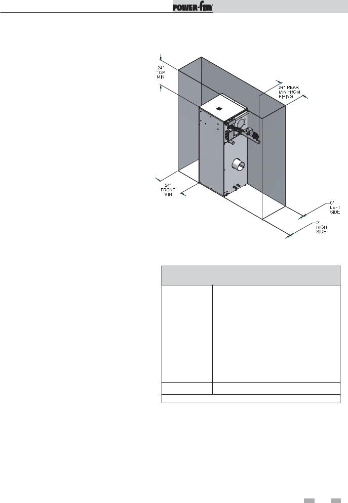
Location of unit |
Recommended service clearances |
1.Locate the appliance so that if water connections should leak, water damage will not occur. When such locations cannot be avoided, it is recommended that a suitable drain pan, adequately drained, be installed under the unit. The pan must not restrict combustion airflow. Under no circumstances is the manufacturer to be held responsible for water damage in connection with this unit, or any of its components.
2.The appliance must be installed so that the ignition system components are protected from water (dripping, spraying, rain, etc.,) during appliance operation and service (circulator replacement, control replacement, etc.,).
3.Appliances located in a residential garage and in adjacent spaces that open to the garage and are not part of the living space of a dwelling unit must be installed so that all burners and burner ignition devices have a minimum clearance of not less than 18" (46 cm) above the floor. The appliance must be located or protected so that it is not subject to physical damage by a moving vehicle.
4.DO NOT install this appliance in any location where gasoline or flammable vapors are likely to be present.
5.The appliance must be installed on a level floor. Combustible floor locations may be used. Maintain required clearances from combustible surfaces.
6.The appliance must not be installed on carpet.
7.The appliance must be installed indoors where it is protected from exposure to wind, rain, and weather.
8.This appliance may condense the products of combustion when operating at water temperatures below 140°F (60°C). Ensure that the appliance is located near an acceptable drain where condensate that may form in the venting system may be properly collected and disposed.
9.Access to rear of appliance MUST be maintained.
Figure 1-1_Recommended Service Clearances
TABLE - 1A
CLEARANCES FROM COMBUSTIBLE CONSTRUCTION
Location |
Clearances |
|
Right Side |
0" |
|
|
|
|
Rear |
6" (15cm) (Minimum 24" (0.61m) suggested |
|
for service to pump and components) |
||
|
||
|
|
|
Left Side |
0" |
|
|
|
|
Front - Alcove* |
(Minimum 24" (0.61m) suggested for service) |
|
|
|
|
Top |
6" (15cm) (Minimum 24" (0.61m) suggested |
|
for service) |
||
|
||
|
|
|
Flue |
2" (51mm) |
Hot Water Pipes 1" (25.4mm)
*An Alcove is a closet without a door.
NOTICE |
Clearances from combustible construction are |
|
noted on the appliance rating plate. |
||
|
9
Installation & Operation Manual
1Determine unit location
Maintain minimum specified clearances for adequate operation. All installations must allow sufficient space for servicing the vent connections, water pipe connections, piping and other auxiliary equipment, as well as the appliance. The clearance labels on each appliance note the same service and combustible clearance requirements as shown above.
Multiple appliances may be installed in a modular boiler or water heater installation. Multiple appliances may be installed side by side with no clearance between adjacent appliances because this appliance is approved for zero clearance from combustible surfaces and no service access is required from the sides.
Consult the Venting section of this manual for specific installation instructions for the appropriate type of venting system that you will be using. Direct Vent and DirectAire venting systems require installation with Category IV flue pipe, sealed air inlet pipe, and air inlet caps, which must meet the manufacturer’s specifications.
Combustion and ventilation air requirements for appliances drawing air from the equipment room
Provisions for combustion and ventilation air must be in accordance with Air for Combustion and Ventilation, of the latest edition of the National Fuel Gas Code, ANSI Z223.1, in Canada, the latest edition of CGA Standard B149 Installation Code for Gas Burning Appliances and Equipment, or applicable provisions of the local building codes.
The equipment room MUST be provided with properly sized openings to assure adequate combustion air and proper ventilation.
Figure 1-2_Combustion Air Direct from Outside
1. If air is taken directly from outside |
the building |
with no duct, provide two permanent |
openings to |
the equipment room (see FIG. 1-2): |
|
(a)Combustion air opening, with a minimum free area of one square inch per 4000 Btu/hr input (5.5 cm2 per kW). This opening must be located within 12" (30 cm) of the bottom of the enclosure.
(b)Ventilation air opening, with a minimum free area of one square inch per 4000 Btu/hr input
(5.5 cm2 per kW). This opening must be located within 12" (30 cm) of the top of the enclosure.
Figure 1-3_Combustion Air Through Ducts
 10
10 
Installation & Operation Manual
1Determine unit location (continued)
2. If combustion and ventilation air is taken from the outdoors using a duct to deliver the air to the equipment room, each of the two openings should be sized based on a minimum free area of one square inch per 2000 Btu/hr (11 cm2 per kW) of input (see FIG. 1-3).
Figure 1-4_Combustion Air from Interior Space
3.If air is taken from another interior space, each of the
two openings specified above should have a net free area of one square inch for each 1000 Btu/hr (22 cm2 per kW) of input, but not less than 100 square inches (645 cm2) (see FIG. 1-4).
Figure 1-5_Combustion Air from Outside - Single Opening
4.If a single combustion air opening is provided to bring combustion air in directly from the outdoors, the opening must be sized based on a minimum free area of one square inch per 3000 Btu/hr (7 cm2 per kW). This opening must be located within 12" (30 cm) of the top of the enclosure (see FIG. 1-5).
TABLE - 1B
MINIMUM RECOMMENDED COMBUSTION
AIR SUPPLY TO EQUIPMENT ROOM
|
|
*Outside Air from |
|
Inside Air from |
Inside Air from |
|
|||
|
Model |
2 Openings Directly from |
*Outside Air from |
2 Ducts Delivered from |
2 Ducts Delivered from Interior |
|
|||
|
Outdoors |
1 Opening Directly |
Outdoors |
Space |
|
||||
|
Number |
|
|||||||
|
Top |
Bottom |
from Outdoors, in2 |
Top |
Bottom |
Top |
Bottom |
|
|
|
|
|
|||||||
|
|
Opening, in2 |
Opening, in2 |
|
Opening, in2 |
Opening, in2 |
Opening, in2 |
Opening, in2 |
|
|
502 |
125 |
125 |
167 |
250 |
250 |
500 |
500 |
|
|
(807 cm2) |
(807 cm2) |
(1077 cm2) |
(1613 cm2) |
(1613 cm2) |
(3226 cm2) |
(3226 cm2) |
|
|
|
|
|
|||||||
|
752 |
188 |
188 |
250 |
375 |
375 |
750 |
750 |
|
|
(1213 cm2) |
(1213 cm2) |
(1613 cm2) |
(2420 cm2) |
(2420 cm2) |
(4839 cm2) |
(4839 cm2) |
|
|
|
|
|
|||||||
|
1002 |
250 |
250 |
333 |
500 |
500 |
1000 |
1000 |
|
|
(1613 cm2) |
(1613 cm2) |
(2149 cm2) |
(3226 cm2) |
(3226 cm2) |
(6452 cm2) |
(6452 cm2) |
|
|
|
|
|
|||||||
|
1302 |
325 |
325 |
433 |
650 |
650 |
1300 |
1300 |
|
|
(2097 cm2) |
(2097 cm2) |
(2794 cm2) |
(4194 cm2) |
(4194 cm2) |
(8388 cm2) |
(8388 cm2) |
|
|
|
|
|
|||||||
|
1501 |
375 |
375 |
500 |
750 |
750 |
1500 |
1500 |
|
|
(2420 cm2) |
(2420 cm2) |
(3226 cm2) |
(4839 cm2) |
(4839 cm2) |
(9678 cm2) |
(9678 cm2) |
|
|
|
|
|
|||||||
|
1701 |
425 |
425 |
567 |
850 |
850 |
1700 |
1700 |
|
|
(2742 cm2) |
(2742 cm2) |
(3658 cm2) |
(5484 cm2) |
(5484 cm2) |
(10968 cm2) |
(10968 cm2) |
|
|
|
|
|
|||||||
|
2001 |
500 |
500 |
667 |
1000 |
1000 |
2000 |
2000 |
|
|
(3226 cm2) |
(3226 cm2) |
(4303 cm2) |
(6452 cm2) |
(6452 cm2) |
(12904 cm2) |
(12904 cm2) |
|
|
|
|
|
|||||||
*Outside air openings shall directly communicate with the outdoors. When combustion air is drawn from the outside through a duct, the net free area of each of the two openings must have twice (2 times) the free area required for Outside Air/2 Openings. The above requirements are for the boiler only; additional gas fired appliances in the equipment room will require an increase in the net free area to supply adequate combustion air for all appliances.
 11
11 
Installation & Operation Manual
1Determine unit location
Combustion air requirements are based on the latest edition of the National Fuel Gas Code, ANSI Z223.1; in Canada refer to the latest edition of CGA Standard CAN B149.1 or B149.2. Check all local code requirements for combustion air.
All dimensions based on net free area in square inches. Metal louvers or screens reduce the free area of a combustion air opening a minimum of approximately 25%. Check with louver manufacturers for exact net free area of louvers. Where two openings are provided, one must be within 12" (30cm) of the ceiling and one must be within 12" (30cm) of the floor of the equipment room. Each opening must have net free area as specified in the chart on page 11 (Table 1B). Single openings shall commence within 12" (30cm) of the ceiling.
CAUTION |
Under |
no |
circumstances |
should the |
|
equipment room ever be under negative |
|||
|
pressure. Particular care should be taken |
|||
|
where exhaust fans, attic fans, clothes dryers, |
|||
|
compressors, air handling units, etc., may |
|||
|
take away air from the unit. |
|
||
|
The combustion air supply must be |
|||
|
completely free of any flammable vapors that |
|||
|
may ignite or chemical fumes which may be |
|||
|
corrosive to |
the appliance. |
Common |
|
|
corrosive chemical fumes which must be |
|||
|
avoided are fluorocarbons and other |
|||
|
halogenated |
compounds, most commonly |
||
|
present as refrigerants or solvents, such as |
|||
|
Freon, |
trichlorethylene, perchlorethylene, |
||
|
chlorine, etc. These chemicals, when burned, |
|||
|
form acids which quickly attack the heat |
|||
|
exchanger finned tubes, headers, flue |
|||
|
collectors, and the vent system. |
|
||
The result is improper combustion and a non-warrantable, premature appliance failure.
EXHAUST FANS: Any fan or equipment which exhausts air from the equipment room may deplete the combustion air supply and/or cause a downdraft in the venting system. Spillage of flue products from the venting system into an occupied living space can cause a very hazardous condition that must be immediately corrected. If a fan is used to supply combustion air to the equipment room, the installer must make sure that it does not cause drafts which could lead to nuisance operational problems with the appliance.
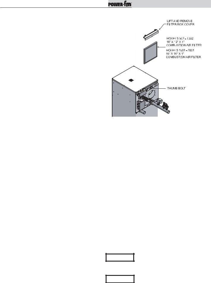
Figure 1-6_Filter Access |
Combustion air filter
This unit has a standard air filter located at the combustion air inlet as shown above in FIG. 1-6. This air filter is provided to help ensure clean air is used for the combustion process. Check this filter every month and replace when it becomes dirty. The filter size on Models 502 -1302 is 16" x 12" x 1" (40.6cm x 30.5cm x 2.5cm) and for Models 1501 - 2001 it’s 16" x 16" x 1" (40.6cm x 40.6cm x 2.5cm). You can find these commercially available filters at any home center or HVAC supply store. Follow the steps below when replacing the combustion air filter:
1.Locate the combustion air filter box mounted on the rear of the appliance.
2.Locate the flat thumb bolt at the top of the air filter box and turn it a 1/4 turn counterclockwise to align it with the slot in the air filter box.
3.Lift and remove the air filter box cover to gain access to the air filter.
4.Slide the air filter out the top of the air filter box.
5.Inspect the air filter for dirt and debris, replace if necessary.
6.Replace the air filter and the air filter box cover. Turn the thumb bolt clockwise a 1/4 turn to secure the air filter box cover to the air filter box.
NOTICE
During construction the air filter should be checked more frequently to ensure it does not become clogged with combustion dirt and debris.
Sustained operation of an appliance with a CAUTION clogged burner may result in nuisance
operational problems, bad combustion, and non-warrantable component failures.
 12
12 

Installation & Operation Manual
2Venting
BEFORE YOU BEGIN
Identify your appliance’s vent system:
This manual covers venting requirements for CAT II/IV and CAT I models. Be sure to correctly identify the type of vent system your appliance requires before proceeding.
Category II/IV Models: See page 15 |
|
|
|
||
Water |
PFN0502PM-M9 |
|
|
|
|
Heaters |
PFN0752PM-M9 |
|
|
|
|
|
PFN1002PM-M9 |
Venting options: |
|
||
|
PFN1302PM-M9 |
|
|||
|
A |
B C |
CAT II requires vent |
||
|
PFN1501PM-M9 |
||||
|
PFN1701PM-M9 |
increaser kit. |
|||
|
PFN2001PM-M9 |
||||
Boilers |
|
|
|
|
|
PBN0502-M9 |
|
|
|
|
|
|
PBN0752-M9 |
D |
E |
F |
|
|
PBN1002-M9 |
|
|||
|
PBN1302-M9 |
|
|||
|
PBN1501-M9 |
|
|
Category II venting is required when common |
|
|
PBN1701-M9 |
NOTICE |
|||
|
PBN2001-M9 |
|
|
venting multiple M9 models . |
|
Category I Models: See page 19
Water PFN0502PM-F9 Heaters PFN0752PM-F9 PFN1002PM-F9 PFN1302PM-F9
PFN1501PM-B9(*)
PFN1701PM-B9(*)
PFN2001PM-B9(*)
Boilers PBN0502-F9 PBN0752-F9 PBN1002-F9 PBN1302-F9 PBN1501-B9(*) PBN1701-B9(*) PBN2001-B9(*)
Venting options:

 G
G 
 H
H 
 I
I
*CAT I “B9” models require field supplied barometric dampers.
DANGER |
Failure to use correct venting materials can result in loss of life from flue gas spillage into working or |
|
living space. |
|
|
Venting Category Definitions: (Reference National Fuel Gas Code ANSI Z223.1)
CAT IV: Positive pressure condensing
An appliance that operates with a positive vent static pressure with a vent gas temperature that may cause excessive condensate production in the vent.
CAT II: Negative pressure condensing
An appliance that operates with a non-positive vent static pressure with a vent gas temperature that may cause excessive condensate production in the vent.
CAT I: Negative pressure non-condensing
An appliance that operates with a non-positive vent static pressure with a vent gas temperature that avoids excessive condensate production in the vent.
 13
13 
Installation & Operation Manual
2Venting
Vent Materials:
Category II/IV Vent Material Suppliers:
Category II/IV flue pipe materials and vent adapters (see FIG. 2-1) can be obtained from the following manufacturers:
Heat-Fab Inc., Saf-T CI Vent with AL29-4C stainless steel
Protech Systems Inc., Fas N Seal Vent with AL29-4C stainless steel
Flex-L International Inc., StaR 34 Vent with AL29-4C stainless steel
Metal-Fab Inc., Corr/Guard Vent with AL29-4C stainless steel
Z-Flex, Z-Vent with AL29-4C stainless steel
Or other listed Category IV vent systems suitable for a condensing, positive pressure, gas fired appliance.
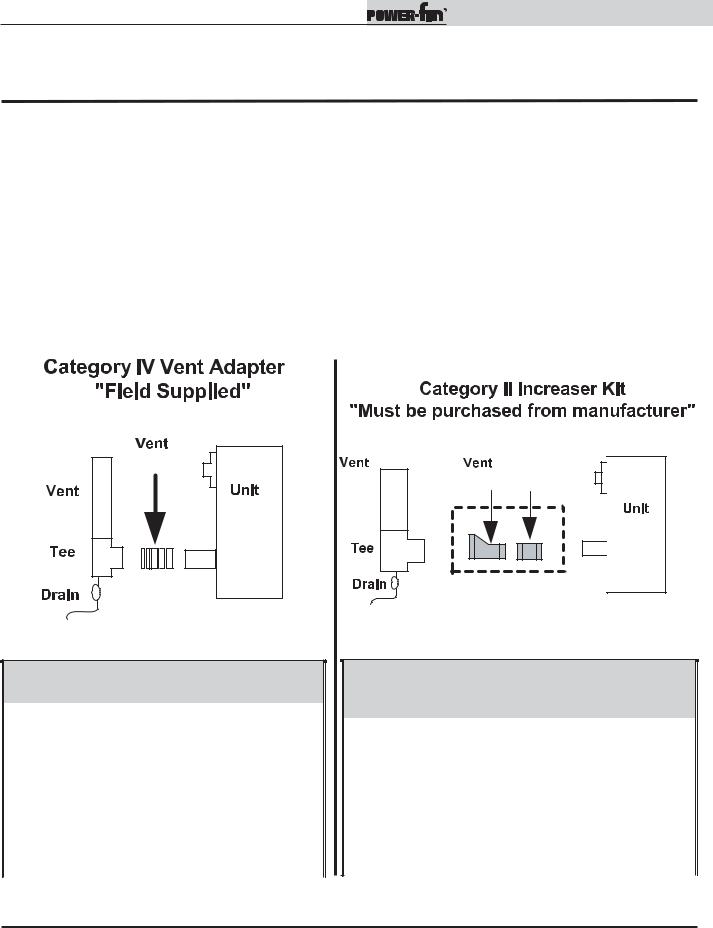
A Category IV flue MUST have all vent joints and seams sealed gastight and have provisions for a drain to properly collect and dispose of condensate that may occur in the venting system.


 *
*
Figure 2-1_Category IV Vent Adapter
TABLE - 2A
FLUE ADAPTER SIZES
|
MODEL |
FLUE ADAPTER SIZE |
|
|
PB/FN0502-M9 |
4" |
|
|
|
|
|
|
PB/FN0752-M9 |
5" |
|
|
|
|
|
|
PB/FN1002-M9 |
6" |
|
|
|
|
|
|
PB/FN1302-M9 |
8" |
|
|
|
|
|
|
PB/FN1501-M9 |
6" |
|
|
|
|
|
|
PB/FN1701-M9 |
7" |
|
|
|
|
|
|
PB/FN2001-M9 |
8" |
|
|
|
|
|
Increaser


 Connector
Figure 2-2_Category IV to II Conversion Kit
TABLE - 2B
CATEGORY IV TO CATEGORY II
CONVERSION KITS
|
MODEL |
FLUE SIZE |
KIT NUMBER |
|
|
PB/FN0502-M9 |
4" to 7" |
KIT3131 |
|
|
|
|
|
|
|
PB/FN0752-M9 |
5" to 9" |
KIT3132 |
|
|
|
|
|
|
|
PB/FN1002-M9 |
6" to 10" |
KIT3133 |
|
|
|
|
|
|
|
PB/FN1302-M9 |
8" to 12" |
KIT3134 |
|
|
|
|
|
|
|
PB/FN1501-M9 |
6" to 8" |
KIT3106 |
|
|
|
|
|
|
|
PB/FN1701-M9 |
7" to 9" |
KIT3107 |
|
|
|
|
|
|
|
PB/FN2001-M9 |
8" to 10" |
KIT3108 |
|
|
|
|
|
|
*Note: The manufacturer of the selected vent material can also provide a vent adapter to connect the vent material to the Power-fin’s vent connection.
Category I Vent Material Suppliers:
Category I venting materials are readily available from your local plumbing/HVAC supply houses.
 14
14 
Installation & Operation Manual
2Venting (continued)
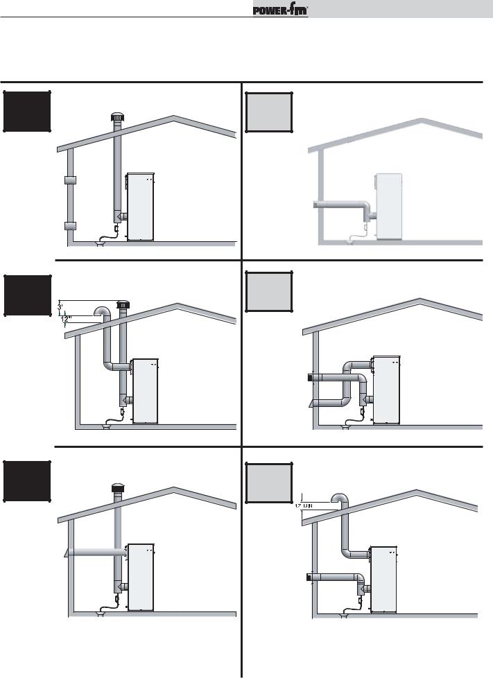
Condensing Vent Options: CAT II & IV
(CAT II vent options A, B, & C requires an adapter kit - see page 14)
A |
Vertical vent with combustion air from |
D |
Sidewall termination with combustion air from |
equipment room - see page 16. |
equipment room - see page 17. |
CAT II/IV |
CAT IV |
CAT II requires an adapter kit.
See page 14.
|
Vertical Direct Vent installation with rooftop |
E |
Horizontal Direct Vent installation with sidewall |
|
B |
combustion air inlet - see page 18. |
|||
combustion air inlet - see page 16. |
CAT II/IV |
CAT IV |
|
CAT II requires an adapter kit.
See page 14.
C |
Vertical DirectAire installation with sidewall |
F |
Horizontal DirectAire installation with vertical |
combustion air inlet - see page 17. |
combustion air inlet - see page 18. |
CAT II/IV |
|
|
|
|
|
|
CAT IV |
||
|
|||||||||
|
|
|
|
|
|
|
|
|
|
|
|
|
|
|
|
|
|
|
|
|
|
|
|
|
|
|
|
|
|
|
|
|
|
|
|
|
|
|
|
CAT II requires an adapter kit.
See page 14.
 15
15 
Installation & Operation Manual
2Venting
Condensing vent options: CAT II & IV
(CAT II vent options A, B, & C requires an adapter kit - see page 14)
A |
Vertical vent with combustion air from equipment room - see page 15. |
The flue outlet terminates on the rooftop. |
|
|
The termination point for the flue products must follow the vertical vent termination clearance requirements |
CAT II/IV |
on pages 27 and 28. These units can be identified by the Category IV and the control number M9 as noted on |
|
the unit’s rating plate. |
CAT II requires an adapter kit.
See page 14.
The flue from this Category IV appliance must have all vent joints and seams sealed gastight. A Category IV vent system has specific vent material and installation requirements.
The flue products in the vent system may be cooled below their dew point and form condensate in the flue. The materials used for a Category IV vent must be resistant to any corrosive damage from flue gas condensate. The flue from a Category IV vent system must have a condensate drain with provisions to properly collect and dispose of any condensate that may occur in the venting system.
Follow all requirements in the General Venting and Category IV General Venting sections for proper installation and for venting flue products to the outdoors with a vertical termination (see pages 22 and 23).
TABLE - 2C
VENT TERMINATION SIZES
|
MODEL |
CAT II |
CAT IV |
MODEL |
CAT II |
CAT IV |
|
|
VENT SIZE |
VENT SIZE |
VENT SIZE |
VENT SIZE |
|
||
|
|
|
|
||||
|
PB/FN0502-M9 |
7" |
4" |
PB/FN1501-M9 |
8" |
6" |
|
|
|
|
|
|
|
|
|
|
PB/FN0752-M9 |
9" |
5" |
PB/FN1701-M9 |
9" |
7" |
|
|
|
|
|
|
|
|
|
|
PB/FN1002-M9 |
10" |
6" |
PB/FN2001-M9 |
10" |
8" |
|
|
|
|
|
|
|
|
|
|
PB/FN1302-M9 |
12" |
8" |
-- |
-- |
-- |
|
|
|
|
|
|
|||
|
|
|
|
|
|
|
|
|
|
|
|
|
|
|
|
B |
Vertical direct vent installation with rooftop combustion air inlet - see |
|
page 15. |
||
|
||
|
The Vertical Direct Vent system is installed with a Category IV flue and a separate combustion air pipe to the |
|
CAT II/IV |
outdoors. The flue outlet and combustion air intake must both terminate on the rooftop. |
CAT II requires an adapter kit.
See page 14.
The termination point for the flue products must follow the vertical vent termination clearance requirements on pages 27 and 28. These units can be identified by the Category IV and the control number M9 as noted on the unit’s rating plate.
The optional Direct Vent system requires the installation of specific venting materials that are purchased locally.
Follow all requirements in the General Venting and Category IV General Venting sections for proper installation and for venting flue products to the outdoors with a vertical termination (see pages 22 and 23).
The Vertical Direct Vent system requires the installation of an additional pipe to supply combustion air from outdoors directly to the appliance. Follow all requirements under the Combustion Air Inlet section on pages 25 and 26.
TABLE - 2D
AIR & VENT TERMINATION SIZES
|
|
CAT II |
CAT IV |
|
CAT II |
CAT IV |
|
||||
|
MODEL |
|
|
|
|
MODEL |
|
|
|
|
|
|
AIR |
VENT |
AIR |
VENT |
AIR |
VENT |
AIR |
VENT |
|
||
|
|
SIZE |
SIZE |
SIZE |
SIZE |
|
SIZE |
SIZE |
SIZE |
SIZE |
|
|
|
|
|
|
|
|
|
|
|
|
|
|
PB/FN0502-M9 |
5" |
7" |
5" |
4" |
PB/FN1501-M9 |
6" |
8" |
6" |
6" |
|
|
|
|
|
|
|
|
|
|
|
|
|
|
PB/FN0752-M9 |
5" |
9" |
5" |
5" |
PB/FN1701-M9 |
7" |
9" |
7" |
7" |
|
|
|
|
|
|
|
|
|
|
|
|
|
|
PB/FN1002-M9 |
6" |
10" |
6" |
6" |
PB/FN2001-M9 |
8" |
10" |
8" |
8" |
|
|
|
|
|
|
|
|
|
|
|
|
|
|
PB/FN1302-M9 |
6" |
12" |
6" |
8" |
-- |
-- |
-- |
-- |
-- |
|
|
|
|
|
|
|
|
|||||
|
|
|
|
|
|
|
|
|
|
|
|
 16
16 
Installation & Operation Manual
2Venting (continued)
Condensing vent options: CAT II & IV
(CAT II vent options A, B, & C requires an adapter kit - see page 14)
C |
CAT II/IV
CAT II requires an adapter kit.
See page 14.
Air Inlet Cap
DirectAire Vertical installation with sidewall combustion air inlet - see page 15.
The DirectAire Vertical with a Sidewall Combustion Air Vent system terminates the flue at the rooftop and air inlet at the sidewall. The flue outlet and combustion air intake terminate in different pressure zones.
The optional DirectAire vent system requires the installation of specific venting materials that are purchased locally.
The termination point for the flue products must follow the vertical vent termination clearance requirements on pages 27 and 28. These units can be identified by the Category IV and the control number M9 as noted on the unit’s rating plate.
Follow all requirements in the General Venting and Category IV General Venting sections for proper installation and for venting flue products to the outdoors with a vertical termination (see pages 22 and 23).
The DirectAire Vertical system requires the installation of an additional pipe to supply combustion air from outdoors directly to the appliance. Follow all requirements under the Combustion Air Inlet section on pages 25 and 26.
Sidewall combustion air inlet: The air inlet cap for the sidewall air inlet must be purchased from the appliance manufacturer.
The part numbers for the required sidewall air inlet cap kit are listed by model. Each kit includes the special combustion air inlet cap for installation on an exterior sidewall. The sidewall air inlet cap supplied in the kit is sized to provide combustion air for a single appliance only.
TABLE - 2E
AIR INLET CAP TERMINATIONS
|
|
CAT II |
CAT IV |
CAT IV |
|
CAT II |
CAT IV |
CAT IV |
|
||||
|
MODEL |
|
|
|
|
KIT |
MODEL |
|
|
|
|
KIT |
|
|
AIR |
VENT |
AIR |
VENT |
AIR |
VENT |
AIR |
VENT |
|
||||
|
|
SIZE |
SIZE |
SIZE |
SIZE |
NUMBER |
|
SIZE |
SIZE |
SIZE |
SIZE |
NUMBER |
|
|
PB/FN0502-M9 |
5" |
7" |
5" |
4" |
SAK3003 |
PB/FN1501-M9 |
6" |
8" |
6" |
6" |
SAK3004 |
|
|
|
|
|
|
|
|
|
|
|
|
|
|
|
|
PB/FN0752-M9 |
5" |
9" |
5" |
5" |
SAK3003 |
PB/FN1701-M9 |
7" |
9" |
7" |
7" |
SAK3005 |
|
|
PB/FN1002-M9 |
6" |
10" |
6" |
6" |
SAK3004 |
PB/FN2001-M9 |
8" |
10" |
8" |
8" |
SAK3006 |
|
|
|
|
|
|
|
|
|
|
|
|
|
|
|
|
PB/FN1302-M9 |
6" |
12" |
6" |
8" |
SAK3004 |
-- |
-- |
-- |
-- |
-- |
-- |
|
|
|
|
|
|
|
|
|
|
|
|
|
|
|
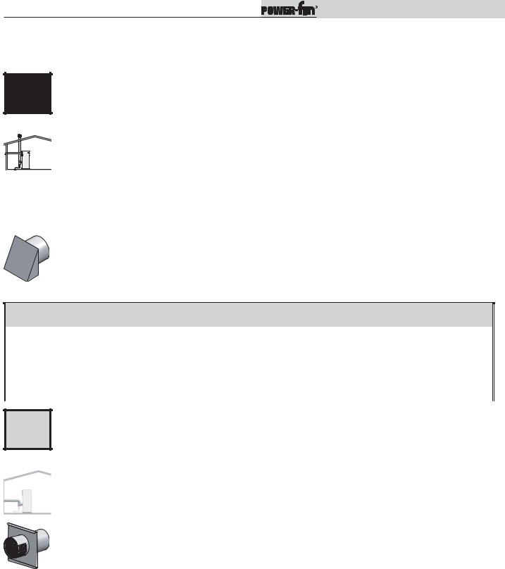
D |
Sidewall termination with combustion air from equipment room - see |
|
page 15. |
||
|
||
|
The connection from the appliance flue outlet to the sidewall vent cap MUST be made with listed Category IV vent |
|
CAT IV |
materials and accessories. The installer must supply suitable vent pipe material. The sidewall vent cap must be |
|
purchased from the appliance manufacturer. |
||
|
||
|
The sidewall vent cap kit includes the wall penetration assembly and the discharge screen assembly. All required |
|
|
Category IV vent pipe and fittings must be purchased locally. |
The termination point for the flue products must follow the sidewall vent termination clearance requirements on pages 28 and 29. These units can be identified by the Category IV and the control number M9 as noted on the unit’s rating plate. Note: PB/FN0502 - 1302 - F9 models with Category I sized vent connection can be sidewall vented with Category IV vent material using the vent decreaser included in the SVK Kit listed in Table 2F. This venting technique with corresponding vent decreasers is not available on the larger PB/FN1501 - 2001 models.
|
Follow all requirements in the General Venting and Category IV General Venting sections for proper installation and |
||||||||
Vent Cap |
for venting flue products to the outdoors with a sidewall termination (see pages 22 and 23). |
|
|||||||
|
|
|
|
|
|
|
|
|
|
|
|
|
|
|
|
|
|
|
|
|
|
|
|
TABLE - 2F |
|
|
|
|
|
|
|
|
FLUE VENT TERMINATION SIZES |
|
|
||||
|
MODEL |
CAT IV |
CAT IV |
MODEL |
CAT IV |
CAT IV |
MODEL |
CAT IV |
CAT IV |
|
VENT SIZE |
KIT |
VENT SIZE |
KIT |
VENT SIZE |
KIT |
|||
|
PB/FN0502-M9 |
4" |
SVK3069 |
PB/FN0502-F9 |
4" |
SVK3056 |
PB/FN1501-M9 |
6" |
SVK3018 |
|
|
|
|
|
|
|
|
|
|
|
PB/FN0752-M9 |
5" |
SVK3070 |
PB/FN0752-F9 |
5" |
SVK3057 |
PB/FN1701-M9 |
7" |
SVK3019 |
|
|
|
|
|
|
|
|
|
|
|
PB/FN1002-M9 |
6" |
SVK3018 |
PB/FN1002-F9 |
6" |
SVK3058 |
PB/FN2001-M9 |
8" |
SVK3068 |
|
|
|
|
|
|
|
|
|
|
|
PB/FN1302-M9 |
8" |
SVK3068 |
PB/FN1302-F9 |
8" |
SVK3059 |
-- |
-- |
-- |
|
|
|
|
|
|
|
|
|
|
 17
17 
Installation & Operation Manual
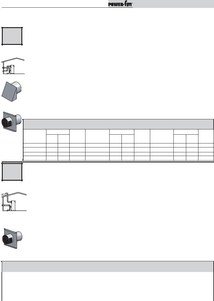
2Venting
Condensing vent options: CAT IV
E |
Horizontal direct vent installation with sidewall combustion air inlet - see page 15.
The horizontal direct vent system is installed with a Category IV flue and a separate combustion air pipe to the outdoors. The flue outlet and combustion air intake must both terminate on the same sidewall.
CAT IV
Air Inlet Cap
The connection from the appliance flue outlet to the sidewall vent cap MUST be made with listed Category IV vent materials and accessories. The installer must supply suitable vent pipe material. The horizontal direct vent must be purchased from the appliance manufacturer.
The termination point for the flue products must follow the sidewall vent termination clearance requirements on pages 28 and 29. These units can be identified by the Category IV and the control number M9 as noted on the unit’s rating plate. Note: PB/FN0502 - 1302 - F9 models with Category I sized vent connection can be sidewall vented with Category IV vent material using the vent decreaser included in the SVK Kit listed in Table 2H. This venting technique with corresponding vent decreasers is not available on the larger PB/FN1501 - 2001 models.
The horizontal direct vent kit includes the wall penetration assembly and the discharge screen assembly for the flue and a combustion air inlet cap. All required vent pipe and fittings must be purchased locally.
Follow all requirements in the General Venting and Category IV General Venting sections for proper installation and for venting flue products to the outdoors with a sidewall termination (see pages 22 and 23).
The horizontal direct vent system requires the installation of an additional pipe to supply combustion air from outdoors directly to the appliance. Follow all requirements under the Combustion Air Inlet section on pages 25 and 26.
|
|
|
|
|
TABLE - 2G |
|
|
|
|
|
||
|
|
|
SIDEWALL AIR AND VENT TERMINATION SIZES |
|
|
|
||||||
Vent Cap MODEL |
CAT IV |
CAT IV |
MODEL |
CAT IV |
CAT IV |
MODEL |
CAT IV |
CAT IV |
||||
AIR |
VENT |
AIR |
VENT |
AIR |
VENT |
|||||||
KIT |
KIT |
KIT |
||||||||||
|
SIZE |
SIZE |
|
|
SIZE |
SIZE |
|
|
SIZE |
SIZE |
|
|
PB/FN0502-M9 |
5" |
4" |
HDK3052 |
PB/FN0502-F9 |
5" |
4" |
HDK3040 |
PB/FN1501-M9 |
6" |
6" |
HDK3049 |
|
PB/FN0752-M9 |
5" |
5" |
HDK3053 |
PB/FN0752-F9 |
5" |
5" |
HDK3041 |
PB/FN1701-M9 |
7" |
7" |
HDK3050 |
|
PB/FN1002-M9 |
6" |
6" |
HDK3049 |
PB/FN1002-F9 |
6" |
6" |
HDK3042 |
PB/FN2001-M9 |
8" |
8" |
HDK3051 |
|
PB/FN1302-M9 |
6" |
8" |
HDK3054 PB/FN1302-F9 |
6" |
8" |
HDK3043 |
-- |
-- |
-- |
-- |
||
F |
CAT IV
Vent Cap
Horizontal DirectAire installation with vertical or sidewall combustion air - page 15.
The Horizontal DirectAire vent system terminates the flue at the sidewall and air inlet at either the rooftop or a sidewall opposite the vent termination. The flue outlet and combustion air intake terminate in different pressure zones.
The connection from the appliance flue outlet to the sidewall vent cap MUST be made with listed Category IV vent materials and accessories. The installer must supply suitable vent pipe material. The Horizontal DirectAire vent cap must be purchased from the appliance manufacturer.
The termination point for the flue products must follow the sidewall vent termination clearance requirements on pages 28 and 29. These units can be identified by the Category IV and the control number M9 as noted on the unit’s rating plate. Note: PB/FN0502 - 1302 - F9 models with Category I sized vent connection can be sidewall vented with Category IV vent material using the vent decreaser included in the SVK Kit listed in Table 2H This venting technique with corresponding vent decreasers is not available on the larger PB/FN1501 - 2001 models.
The Horizontal DirectAire vent system with a vertical air inlet requires a sidewall vent kit. The Horizontal DirectAire vent system with a sidewall air inlet requires a horizontal direct vent kit. All required vent pipe and fittings must be purchased locally.
Follow all requirements in the General Venting and Category IV General Venting sections for proper installation and for venting flue products to the outdoors with a sidewall termination (see pages 22 and 23).
The Horizontal DirectAire vent system requires the installation of an additional pipe to supply combustion air from outdoors directly to the appliance. Follow all requirements under the Combustion Air Inlet section on pages 24 and 25.
TABLE - 2H
SIDEWALL VENT TERMINATION SIZES
|
MODEL |
CAT IV |
CAT IV |
MODEL |
CAT IV |
CAT IV |
MODEL |
CAT IV |
CAT IV |
|
|||
|
AIR |
VENT |
KIT |
AIR |
VENT |
KIT |
AIR |
VENT |
KIT |
|
|||
|
|
SIZE |
SIZE |
|
SIZE |
SIZE |
|
SIZE |
SIZE |
|
|||
|
|
|
|
|
|
|
|
||||||
|
PB/FN0502-M9 |
5" |
4" |
SVK3069 |
PB/FN0502-F9 |
5" |
4" |
SVK3056 |
PB/FN1501-M9 |
6" |
6" |
SVK3018 |
|
|
PB/FN0752-M9 |
5" |
5" |
SVK3070 |
PB/FN0752-F9 |
5" |
5" |
SVK3057 |
PB/FN1701-M9 |
7" |
7" |
SVK3019 |
|
|
PB/FN1002-M9 |
6" |
6" |
SVK3018 |
PB/FN1002-F9 |
6" |
6" |
SVK3058 |
PB/FN2001-M9 |
8" |
8" |
SVK3068 |
|
|
PB/FN1302-M9 |
6" |
8" |
SVK3068 |
PB/FN1302-F9 |
6" |
8" |
SVK3059 |
-- |
-- |
-- |
-- |
|
 18
18 
Installation & Operation Manual
2Venting (continued)
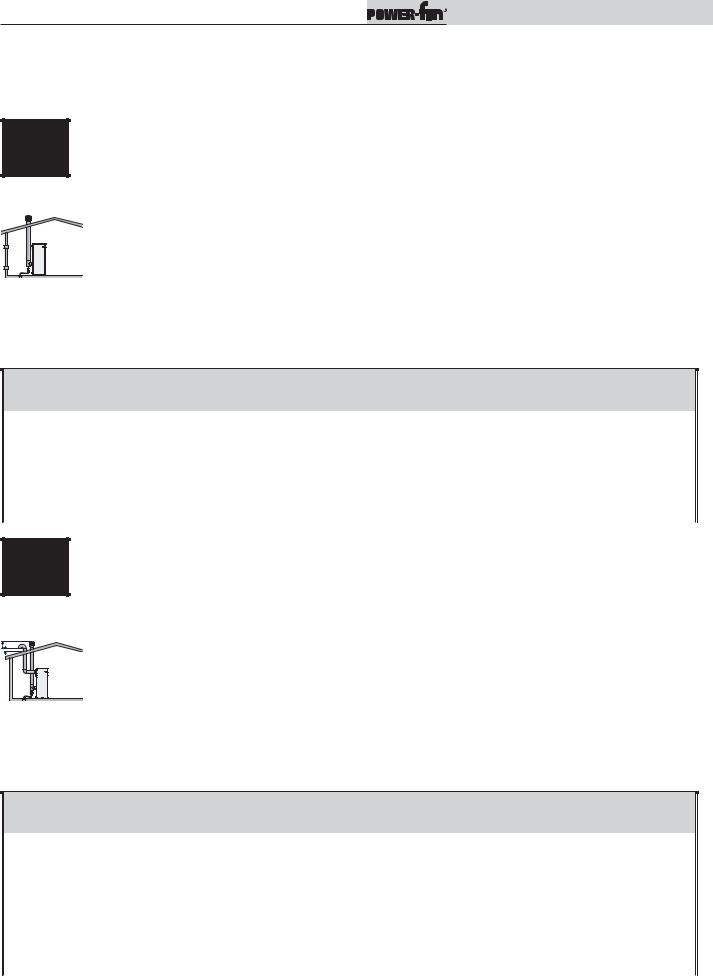
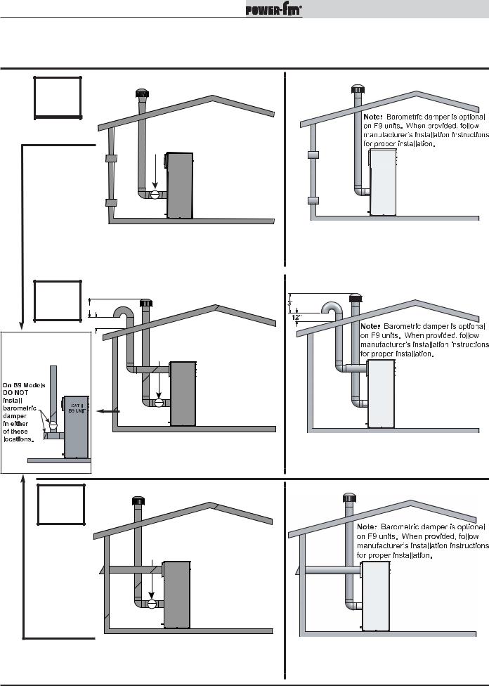
Non-Condensing Vent Options: CAT I
G
A required field supplied barometric damper MUST BE installed in location shown.
CAT I - B9
Vertical negative draft venting system - see pages 20 and 21.
H |
3' |
|
|
|
|
12" |
|
INCORRECT |
|
A required field supplied |
|
|
barometric damper MUST BE |
||
INSTALLATIONS |
|||
installed in location shown. |
|||
|
|
||
CAT I - F9
Vertical negative draft venting system - see page 20.
CAT I - B9
DirectAire vertical venting with vertical air inlet - see pages 20 and 21.
CAT I - F9
DirectAire vertical venting with vertical air inlet - see page 20.
I
A required field supplied barometric damper MUST BE installed in location shown.
CAT I - B9
DirectAire vertical venting with sidewall inlet - see pages 20 and 21.
CAT I - F9
DirectAire vertical venting with sidewall inlet - see page 20.
 19
19 
Installation & Operation Manual
2Venting
Non-Condensing vent options: CAT I
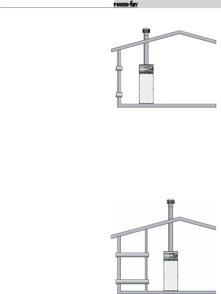
Vertical negative draft venting system - see page 19.
GUnits that may be vented with a Category I, Type “B” vent material operate with limited burner modulation. These units can be identified by the Category I and the control number F9 or B9 as noted on the unit’s rating plate. These are the only units that can be vented with standard double-wall vent material. See the General
|
CAT I |
Venting and the Negative Draft General Venting on pages 21 and 22. The flue must terminate at the rooftop and |
|||||||||
|
|
|
|
|
|
|
follow the clearance requirements on pages 27 and 28. Combustion air is supplied from the equipment room. |
||||
|
|
|
|
|
|
|
The installation of the vent must conform to the latest edition of the National Fuel Gas Code, ANSI Z223.1, in |
||||
|
|
|
|
|
|
|
|||||
|
|
|
|
|
|
|
|||||
|
|
|
|
|
|
|
Canada, the latest edition of CGA Standard B149 Installation Code for Gas Burning Appliances and Equipment. |
||||
|
|
|
|
|
|
|
The negative draft in a conventional vent installation must be within the range of 0.02 to 0.08 inches w.c. to |
||||
|
|
|
|
|
|
|
ensure proper operation. Make all draft readings while the unit is in stable operation (approximately 2 to 5 |
||||
|
|
|
|
|
|
|
|||||
|
|
|
|
|
|
|
minutes). |
|
|
|
|
|
|
|
|
|
|
|
|
|
|
|
|
|
|
|
|
|
|
|
|
|
|
|
|
|
|
|
|
|
|
|
|
|
TABLE - 2I |
|
|
|
|
|
|
|
|
|
|
FIELD PROVIDED TERMINATIONS |
|
||
|
|
|
|
|
|
|
MODEL |
VENT SIZES |
|
MODEL |
VENT SIZES |
|
|
|
|
|
|
|
PB/FN0502-F9 |
7" |
|
PB/FN1501-B9 |
12" |
|
|
|
|
|
|
|
PB/FN0752-F9 |
9" |
|
PB/FN1701-B9 |
14" |
|
|
|
|
|
|
|
PB/FN1002-F9 |
10" |
|
PB/FN2001-B9 |
14" |
|
|
|
|
|
|
|
PB/FN1302-F9 |
12" |
|
-- |
-- |
|
|
|
|
|
|
|
|
|
|
|
|
DirectAire vertical venting with vertical air inlet - see page 19.
HUnits that may be vented with a Category I, Type “B” vent material operate with limited burner modulation. These units can be identified by the Category I and the control number F9 or B9 as noted on the unit’s rating plate. These are the only units that can be vented with standard double-wall vent material. See the General
CAT I
Venting and the Negative Draft General Venting sections on pages 21 and 22. The flue must terminate at the rooftop and follow the clearance requirements on pages 27 and 28. Combustion air is supplied vertically from the rooftop. The installation of the vent must conform to the latest edition of the National Fuel Gas Code, ANSI Z223.1, in Canada, the latest edition of CGA Standard B149 Installation Code for Gas Burning Appliances and Equipment. The negative draft in a conventional vent installation must be within the range of 0.02 to 0.08 inches w.c. to ensure proper operation. Make all draft readings while the unit is in stable operation (approximately 2 to 5 minutes).
TABLE - 2J
FIELD PROVIDED TERMINATIONS
|
MODEL |
AIR SIZES |
VENT SIZES |
MODEL |
AIR SIZES |
VENT SIZES |
|
|
PB/FN0502-F9 |
5" |
7" |
PB/FN1501-B9 |
6" |
12" |
|
|
PB/FN0752-F9 |
5" |
9" |
PB/FN1701-B9 |
7" |
14" |
|
|
PB/FN1002-F9 |
6" |
10" |
PB/FN2001-B9 |
8" |
14" |
|
|
PB/FN1302-F9 |
6" |
12" |
-- |
-- |
-- |
|
DirectAire vertical with sidewall air inlet - see page 19.
IUnits that may be vented with a Category I, Type “B” vent material operate with limited burner modulation. These units can be identified by the Category I and the control number F9 or B9 as noted on the unit’s rating
|
CAT I |
|
plate. These are the only units that can be vented with standard double-wall vent material. See the General |
|||||||||||||||
|
Venting and the Negative Draft General Venting sections on pages 21 and 22. The flue must terminate at the |
|||||||||||||||||
|
|
|
|
|
|
|
|
|||||||||||
|
|
|
|
|
|
|
|
rooftop and follow the clearance requirements on pages 27 and 28. Combustion air is supplied horizontally |
||||||||||
|
|
|
|
|
|
|
|
|||||||||||
|
|
|
|
|
|
|
|
from the outside. The installation of the vent must conform to the latest edition of the National Fuel Gas Code, |
||||||||||
|
|
|
|
|
|
|
|
|||||||||||
|
|
|
|
|
|
|
|
|||||||||||
|
|
|
|
|
|
|
|
ANSI Z223.1, in Canada, the latest edition of CGA Standard B149 Installation Code for Gas Burning Appliances |
||||||||||
|
|
|
|
|
|
|
|
and Equipment. The negative draft in a conventional vent installation must be within the range of 0.02 to 0.08 |
||||||||||
|
|
|
|
|
|
|
|
inches w.c. to ensure proper operation. Make all draft readings while the unit is in stable operation |
||||||||||
|
|
|
|
|
|
|
|
|||||||||||
|
|
|
|
|
|
|
|
(approximately 2 to 5 minutes). |
|
|
|
|
|
|
||||
|
|
|
|
|
|
|
|
|
|
|
|
|
|
|||||
|
|
|
|
|
|
|
|
|
|
|
|
|
|
|
|
|
|
|
|
|
|
|
|
|
|
|
|
|
|
|
|
TABLE - 2K |
|
|
|
|
|
|
|
|
|
|
|
|
|
|
|
|
|
|
AIR INLET CAP |
|
|
|
|
|
|
|
|
|
|
|
|
|
|
|
|
|
|
|
|
|
|
||
|
|
|
|
|
|
|
|
|
|
MODEL |
AIR |
VENT |
KIT |
MODEL |
AIR |
VENT |
KIT |
|
|
|
|
|
|
|
|
|
|
|
SIZES |
SIZES |
NUMBER |
SIZES |
SIZES |
NUMBER |
|||
|
|
|
|
|
|
|
|
|
|
|
|
|||||||
|
|
|
|
|
|
|
|
|
|
PB/FN0502-F9 |
5" |
7" |
SAK3003 |
PB/FN1501-B9 |
6" |
12" |
SAK3004 |
|
|
Air Inlet Cap |
|
|
|
|
|
|
|
|
|
|
|||||||
|
|
|
PB/FN0752-F9 |
5" |
9" |
SAK3003 |
PB/FN1701-B9 |
7" |
14" |
SAK3005 |
||||||||
|
|
|
|
|
|
|
|
|
|
PB/FN1002-F9 |
6" |
10" |
SAK3004 |
PB/FN2001-B9 |
8" |
14" |
SAK3006 |
|
|
|
|
|
|
|
|
|
|
|
PB/FN1302-F9 |
6" |
12" |
SAK3004 |
-- |
-- |
-- |
-- |
|
|
|
|
|
|
|
|
|
|
|
|
|
|
|
|
|
|
|
|
 20
20 
Installation & Operation Manual
2Venting (continued)
Common Venting CAT II:
Flues of multiple Power-fins may be combined by incorporating a vent increaser to change the Category IV appliance to a Category II vent system which can be common vented using an engineered vent system. The increaser kit must be provided by the manufacturer and the combined engineered vent system must be designed to ensure that flue products will be properly exhausted from the building at all times. Failure to use the correct vent increaser or a properly sized vent system may result in a hazardous condition where flue gases spill into an occupied living space. Consult a vent designer to determine the diameter of the common vent pipe required for combined vent installation. It is recommended that all vent joints and seams are sealed gastight. This vent system has specific vent material and installation requirements. The negative draft in a conventional vent installation must be within the range of 0.02 to 0.08 inches w.c. to ensure proper operation. Make all draft readings while the unit is in stable operation (approximately 2 to 5 minutes).
Common Venting CAT I - Venting options: G, H, & I (F9 / B9)
The negative draft in a conventional vent installation must be within the range of 0.02 to 0.08 inches w.c. to ensure proper operation. Make all draft readings while the unit is in stable operation (approximately 2 to 5 minutes).
As noted in the diagrams on page 19, F9 models do not require a barometric damper in a single stack installation as illustrated. However, common venting of multiple negative draft appliances requires that you MUST install a barometric damper on each unit to regulate draft. Install per the requirements of the latest edition of the National Fuel Gas Code, ANSI Z223.1 and/or CAN/CGAB149 Installation Code.
Common Venting systems may be too large when an existing unit is removed. At the time of removal of an existing appliance, follow the steps below with each appliance remaining connected to the common venting system placed in operation, while other appliances remaining connected to the common venting system are not in operation:
a.Seal any unused opening in the common venting system.
b.Visually inspect the venting system for proper size and horizontal pitch and determine there is no blockage or restriction, leakage, corrosion, and other unsafe condition.
c.Insofar as is practical, close all building doors and windows and all doors between the space in which the appliances remaining connected to the common venting system are located and other spaces of the building. Turn on clothes dryers and any other appliances not connected to the common venting system. Turn on any exhaust fans, such as range hoods and bathroom exhausts, so they will operate at maximum speed. Do not operate a summer exhaust fan. Close fireplace dampers.
d.Place in operation the appliance being inspected. Follow the lighting (operating) instructions in this manual (see page 51). Adjust thermostat so appliance will operate continuously.
e. Test for spillage at the draft hood / relief opening after five (5) minutes of main burner operation. Use the flame of a match or candle, or smoke from a cigarette, cigar, or pipe.
f.After it has been determined that each appliance remaining connected to the common venting system vents properly when tested as above, return doors, windows, exhaust fans, fireplace dampers, and other gas burning appliances to their previous conditions of use.
g.Any improper operation of the common venting system should be corrected so that the installation conforms to the latest edition of the National Fuel Gas Code, ANSI Z223.1, in Canada, the latest edition of CGA Standard B149 Installation Code for Gas Burning Appliances and Equipment.
When resizing any portion of the common venting system, the common venting system should be resized to approach the minimum size as determined using the appropriate tables in the latest edition of the National Fuel Gas Code, ANSI Z223.1, in Canada, the edition of CGA Standard B149 Installation Code for Gas Burning Appliances and Equipment.
B9 Barometric Damper CAT I - Venting options: G, H, & I (Required for B9)
Category I B9 units require a field supplied barometric damper to be installed at the rear of the unit. The damper should be installed directly after the flue collar prior to going vertical with the flue pipe as shown in the figures on page 19. The damper position indicator should be visible after its installation. The damper should be sized appropriately for the flue pipe. 1501 B9 models require a 12" damper. 1701 and 2001 B9 models require a 14" damper. When using barometric dampers, make-up air must be supplied to the room in order for them to function. This location is important and specifically required for the B9 appliance and may not match suggested locations found in the damper manufacturer’s installation manual. Otherwise follow the manufacturer’s recommendations on damper installation and operation. The negative draft in a conventional vent installation must be within the range of 0.02 to 0.08 inches w.c. to ensure proper operation. Make all draft readings while the unit is in stable operation (approximately 2 to 5 minutes).
Note: Barometric dampers may also be required on 502, 752, 1002, and 1302 “F9” models for use in high draft areas and are required
when common venting multiple negative draft Category I appliances (see Common Venting CAT I section). |
21 |
|
Installation & Operation Manual
2Venting
CAT I, II,& IV General venting information-Vent options: All Categories
Vent installation for connection to gas vents or chimneys must be in accordance with “Venting of Equipment”, of the latest edition of the National Fuel Gas Code, ANSI Z223.1, in Canada, the latest edition of CAN/CGA Standard B149 Installation Code for Gas Burning Appliances and Equipment or applicable provisions of the local building codes.
All venting applications where combustion air is drawn from the equipment room must have adequate combustion and ventilation air supplied to the equipment room in accordance with the latest edition of CAN/CGA Standard B149 Installation Code for Gas Burning Appliances and Equipment or applicable provisions of the local building codes.
The distance of the vent terminal from adjacent buildings, windows that open and building openings MUST comply with the minimum clearances stated in this manual and the latest edition of the National Fuel Gas Code, ANSI Z223.1, in Canada, the latest edition of CAN/CGA Standard B149 Installation Code for Gas Burning Appliances and Equipment.
The vent connection is made directly to the flue outlet opening on the rear of the unit. The connection from the appliance vent to the stack must be made as direct as possible with no reduction in diameter.
NOTICE |
Examine the venting system at least once a year. Check all joints and vent pipe connections for tightness. Also |
|
check for corrosion or deterioration. Immediately correct any problems observed in the venting system. |
||
|
CAT IV Specific venting information: Vent Options A, B, C, D, E, & F
A Category IV venting system operates with a positive pressure in the vent. This positive pressure is generated by the internal combustion air blower which operates the combustion process and also exhausts the flue products from the building. The Category IV flue from this appliance cannot be combined with the vent from any other appliance. The Category IV flue from this appliance must be a dedicated stack, there is one exception however. The Category IV flues from multiple Power-fin appliances may only be combined when using an engineered vent system incorporating an induced draft fan to ensure that flue products will be properly exhausted from the building at all times. Failure to use a properly sized induced draft fan on a combined Category IV vent installation may result in a hazardous condition where flue gases spill into an occupied living space. Consult the induced draft fan manufacturer to size the induced draft fan and to determine the diameter of the common vent pipe required for a combined vent installation. The flue from this Category IV appliance must have all vent joints and seams sealed gastight. A Category IV vent system has specific vent material and installation requirements.
The flue products in the vent system may be cooled below their dew point and form condensate in the flue. The flue materials used for a Category IV vent must be resistant to any corrosive damage from flue gas condensate. The flue from a Category IV vent system must have a condensate drain with provisions to properly collect and dispose of any condensate that may occur in the venting system.
The connection from the appliance vent to the stack or vent termination outside the building must be made with listed Category IV vent material and must be as direct as possible. The Category IV vent and accessories such as firestop spacers, thimbles, caps, etc., must be installed in accordance with the vent manufacturer’s instructions. The vent connector and firestop must provide correct spacing to combustible surfaces and seal to the vent connector on the upper and lower sides of each floor or ceiling through which the vent connector passes.
Any vent materials specified must be listed by a nationally recognized test agency for use as a Category IV vent material.
The venting system must be planned so as to avoid possible contact with concealed plumbing or electrical wiring inside walls, floors, or ceilings. Locate the appliance as close as possible to a chimney or gas vent.
Horizontal portions of the venting system shall be supported to prevent sagging. Horizontal runs should slope upwards not less than a 1/4 inch per foot from the drain tee installed in the flue to the vertical portion of the flue or to the vent terminal on sidewall venting installations. This ensures proper removal of any condensate that may form in the flue. Follow the installation instructions from the vent material manufacturer.
 22
22 
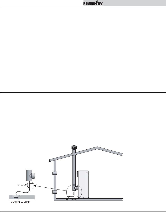
Installation & Operation Manual
2Venting (continued)
CAT IV Specific venting information (continued): Vent options A, B, C, D, E, &F
Do not use an existing chimney as a raceway if another appliance or fireplace is vented through the chimney. The weight of the venting system must not rest on the unit. Adequate support of the venting system must be provided in compliance with local codes and other applicable codes. All connections should be secured and sealed per the vent manufacturer’s specifications.
Vent connectors serving appliances vented by natural draft shall not be connected to any portion of the Category IV positive pressure vent system used by this appliance. Connection of a negative draft flue into the positive pressure stack from this appliance may cause flue products to be discharged into an occupied living space causing serious health injury.
When a Category IV vent system is disconnected for any reason, the flue must be reassembled and resealed according to the vent manufacturer’s instructions.
The flue may terminate either vertically at the rooftop or horizontally on a sidewall. Refer to the specific vent termination sections for information about recommended vent termination location and clearances.
Length of flue pipe
The installed length of the Category IV flue from the appliance to the point of termination, outside of the building, must not exceed a maximum of 50 equivalent feet (15.2m) in length. Subtract 5 feet (1.5m) of equivalent length for each 90° elbow installed in the vent. Subtract 2 1/2 feet (0.7m) of equivalent length for each 45° elbow installed in the vent.
CAT II/IV Drain Tee Requirements: Vent options A, B, C, D, E, &F
Drain tee installation
A drain tee must be installed in the Category II & IV vent pipe to collect and dispose of any condensate that may occur in the vent system. The drain tee should be installed at the point where the flue turns vertical for a rooftop termination or as one of the first fittings in a horizontal flue connector that will terminate on a sidewall. Ensure that horizontal portions of the vent are properly sloped to allow condensate to be evacuated at the drain tee. Plastic drain tubing, sized per the vent manufacturer’s instructions, shall be provided as a drain line from the tee. The drain tubing must have a trap provided by a 10" (25.4cm) diameter circular trap loop in the drain tubing. Prime the trap loop by pouring a small quantity of water into the drain hose before assembly to the vent. Secure the trap loop in position with nylon wire ties. Use caution not to collapse or restrict the condensate neutralization system or a suitable drain for disposal of condensate that may occur in the Category IV vent system. Ensure that the drain from the condensate tee is not exposed to freezing temperatures. See Section 7, Startup - Freeze Protection for more information.
Figure 2-3_Drain Tee Installation
CAT I Specific venting information:
Follow all requirements set forth in the latest edition of the National Fuel Gas Code, ANSI Z223.1, in Canada, the latest edition of the CAN/CGA Standard B149 Installation Code for Gas Burning Appliances and Equipment or applicable provisions of the local building codes.
 23
23 
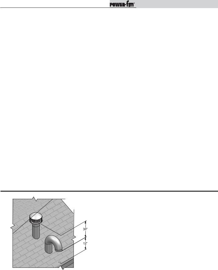
Installation & Operation Manual
2Venting
Vertical Air Inlet: Vent options B, F, & H
Vertical combustion air inlet
The air inlet cap for the vertical rooftop air inlet is assembled from components purchased locally. The air inlet cap consists of two 90° elbows installed at the point of termination for the air inlet pipe. The first 90° elbow is installed on the rooftop at the highest vertical point of the air inlet pipe and turned horizontal, the second 90° elbow is installed on the horizontal outlet of the first elbow and turned down.
A 90° elbow and a 90° street elbow may be used to make this assembly. If a straight piece of pipe is used between the two elbows, it should not exceed 6 inches (152mm) in length. The termination elbow on the air inlet must be located a minimum of 12 inches (0.30m) above the roof or above normal levels of snow accumulation.
Location of a vertical air inlet cap
Incorrect installation and/or location of the air inlet cap can allow the discharge of flue products to be drawn into the combustion process on the heater. This can result in incomplete combustion and potentially hazardous levels of carbon monoxide in the flue products. This will cause operational problems with the heater and possible spillage of flue products that can cause personal injury, death, or property damage.
The point of termination for the combustion air inlet cap MUST be at least 3 feet (0.91m) below the point of flue gas termination (vent cap) if it is located within a 10 foot (3.05m) radius of the flue outlet. Use care to ensure that the 90° elbow assembly is properly installed on the air inlet pipe.
The combustion air inlet cap must not be installed closer than 10 feet (3.05m) from an inside corner of an L-shaped structure.
The termination point of the combustion air inlet cap must be installed at least one foot (0.30m) above the rooftop and above normal snow levels.
The combustion air cap assembly used MUST adequately protect the combustion air inlet from wind and weather.
Combustion air supplied from outdoors must be free of contaminants (see Combustion and Ventilation Air, page 10). To prevent recirculation of flue products into the combustion air inlet, follow all instructions in this section.
The combustion air inlet caps for multiple appliance installations must maintain the minimum 3 foot (0.91m) clearance below the closest vertical flue outlet if within 10 feet (3.05m).
Figure 2-4_Vertical Air Inlet Clearances
 24
24 
 Loading...