


V0603MHS12WH
LITTELFUSE V0603MHS12WH, V0603MHS12NH, V0603MHS12H, V0603MHS03WH, V0603MHS03H Datasheet
...
Surface Mount Varistors
1
Multilayer High Speed Transient Voltage Surge Suppressor
MHS Varistor Series
The Multilayer High-Speed MHS Series is a very-low capacitance
extension to the Littelfuse ML family of Transient Voltage Surge
Suppression devices available in an 0402 and 0603-size surface
mount chip.
The MHS series provides protection from ESD and EFT in high-speed
data-line and other high frequency applications. The low capacitance of
the MHS Series permits usage in analog or digital circuits where it will
not attenuate or distort the desired signal or data.
Their small size is ideal for high-density printed circuit boards, being
typically applied to protect intergrated circuits and other sensitive
components. They are particularly well suited to suppress ESD events
including those specified in IEC 61000-4-2 or other standards used for
ElectroMagnetic Compliance (EMC) testing.
The MHS series is manufactured from semiconducting ceramics and is
supplied in a leadless, surface mount package. The MHS Series is also
compatible with modern reflow and wave soldering processes.
Littelfuse Inc. manufactures other Multilayer Varistor Series products,
see the ML, MLE, MLN and AUML series data sheets.
Features
• 3pF & 12pF Capacitance Versions Suitable for High Speed
Data-Rate Lines
• ESD Rated to IEC 61000-4-2 (Level 4)
• EFT/B Rated to IEC 61000-4-4 (Level 4)
• Low Leakage Currents
• -55
o
C to +125
o
C Operating Temperature Range
• Inherently Bi-directional
Applications
• Data, Diagnostic I/O Ports
• Universal Serial Bus (USB)
• Video & Audio Ports
• Portable/Hand-Held Products
• Mobile Communications
• Computer/DSP Products
• Industrial Instruments Including Medical
Absolute Maximum Ratings For ratings of individual members of a series, see device ratings and specifications table.
Continuous:
Steady State Applied Voltage: DC Voltage Range (V
M(DC)
):V0402/0603MHS03 . . . . . . . . . . . . . . . . . . . . . . . . . . . . . . . . . . ≤ 42 V
V0402/0603MHS12 . . . . . . . . . . . . . . . . . . . . . . . . . . . . . . . . . ≤ 18 V
Operating Ambient Temperature Range (T
A
) . . . . . . . . . . . . . . . . . . . . . . . . . . . . . . . . . . . . . . . . . . . . . . . . . . . . . . . . . . . . -55 to + 125
O
C
Storage Temperature Range (T
STG
) . . . . . . . . . . . . . . . . . . . . . . . . . . . . . . . . . . . . . . . . . . . . . . . . . . . . . . . . . . . . . . . . . . -55 to + 150
O
C
MHS SERIES UNITS
Multilayer High Speed Transient Voltage Surge Suppressor
MHS Varistor Series
Surface Mount Varistors
2
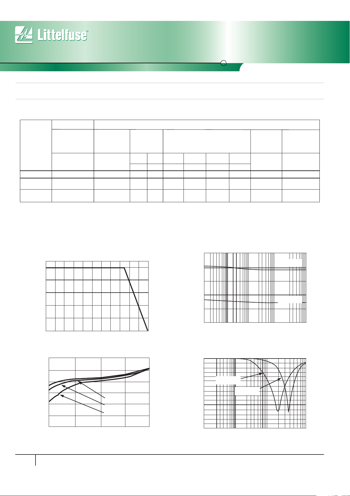
Device Ratings and Specifications
Temperature De-rating
For applications exceeding 125oC ambient temperature, the peak surge
current and energy ratings must be reduced as shown in Figure 1.
PAR T
NUMBER
MAX RATINGS
(125°C)
PERFORMANCE SPECIFICATIONS (25°C)
MAXIMUM
ESD CLAMP
VO LTAGE
(NOTE 1)
W
TM Clamp
(Note 2)
8kV
CONTACT
NOTES:
1.
2.
Tested to IEC-61000-4-2 Human Body Model (HBM) discharge test circuit.
3.
Direct discharge to device terminals (IEC preferred test method).
4.
Corona discharge through air (represents actual ESD event).
Capacitance may be customized, contact your Littelfuse Sales Representative.
3.5V
V0402MHS12 0.025 125 160 0.1
V0402MHS03 0.010 300 400 0.1
MAXIMUM NON-
REPETITIVE
SURGE ENERGY
(10/1000µS)
Clamp
(Note 3)
15kV
AIR
MAXIMUM LEAKAGE CURRENT AT
SPECIFIED DC VOLTAGE
5.5V 9V
15V
I
L
(J) (V) (V) (µA)
(µA) (µA)
(µA)
TYPICAL
CAPACITANCE
AT 1MHz
(1V p-p)
(NOTE 4)
C
(pF)
TYPICAL
INDUCTANCE
(from Impedance
Analysis)
L
(nH)
0.15
0.15
1.00
0.25
5.00
0.50
12
3
<1.0
<1.0
MAXIMUM
CLAMPING
VO LTAGE
AT 1A (8X20µs)
(Vc)
55
110
P I
L
I
L
V0603MHS12 0.025 125 160 0.1
V0603MHS03 0.010 300 400 0.1
0.15
0.15
1.00
0.25
5.00
0.50
12
3
<1.0
<1.0
55
110
100
80
60
40
20
0
-55 50 60 70 80 90 100 110 120 130 140 150
PERCENT OF RATED VALUE
AMBIENT TEMPERATURE (
o
C)
FIGURE 1. PEAK CURRENT AND ENERGY DERATING CURVE
FIGURE 3. NOMINAL VOLTAGE STABILITY TO MULTIPLE
ESD IMPULSES (8KV CONTACT DISCHARGES
PER IEC 61000-4-2)
60
10
1
CURRENT (A)
NOMINAL VOLTAGE AT 1mADC
10
100
1000
10000
20
30
40
50
V0402MHS03
V0402MHS12
V0603MHS03
V0603MHS12
0.0001
0.001
CURRENT (mA)
0
0.01 0.1 1
5
10
20
25
30
15
25
85
125
VARISTOR VOLTAGE (V)
o
o
o
FIGURE 2: STANDBY CURRENT AT NORMALIZED VARISTOR
VOLTAGE AND TEMPERATURE
FIGURE 4. INSERTION LOSS (S21) CHARACTERISTICS
-30
FREQUENCY (MHz)
INSERTION LOSS (dB)
10
100
1000
10000
-20
-10
0
V0402MHS12
V0402MHS03
V0603MHS12
V0603MHS03
 Loading...