


DCS 6000
User Manual
Digital Conference System
CU 6005/6010/6011 Central Unit
Central Unit for series DCS 6000 Voting Units, Conference Units, Interpreter Units, Ambient Noise Microphone, Channels Selectors and Audio Output Units
Danish Interpretation Systems |
DIS |
Danish Interpretation Systems |
User Manual |
Copyright © 2007 DIS CU6005 6010 6011 REV V.DOC 16-07-2007
No part of this publication may be reproduced or utilised in any form or by any means without permission in writing from the publisher.

Danish Interpretation Systems |
User Manual |
List of Contents |
|
List of Contents..................................................... |
3 |
Important .............................................................. |
5 |
Compliancy........................................................ |
5 |
Important safety instructions........................... |
5 |
Labels ................................................................. |
5 |
Installation precautions .................................... |
5 |
Cleaning & Repacking...................................... |
6 |
Warranty ........................................................... |
6 |
Description of the DCS 6000 system ................... |
7 |
Features.............................................................. |
7 |
System components........................................... |
8 |
Central equipment etc...................................... |
8 |
Interpreter equipment ...................................... |
8 |
Voting equipment............................................ |
8 |
Conference equipment and channel selectors . 8 |
|
Operating instructions ......................................... |
9 |
CU 6010 Central Unit ....................................... |
9 |
General description ......................................... |
9 |
Features ........................................................... |
9 |
Feature License ............................................... |
9 |
User Controls, indications & connectors....... |
10 |
System settings.............................................. |
12 |
Normal Operation.......................................... |
20 |
CU 6011 Central Unit ..................................... |
21 |
General description ....................................... |
21 |
CU 6005 Central Unit ..................................... |
22 |
General description ....................................... |
22 |
Features ......................................................... |
22 |
Feature License ............................................. |
22 |
User Controls, indications & connectors....... |
23 |
System settings .............................................. |
23 |
Normal Operation .......................................... |
23 |
|
|
System Setup........................................................ |
24 |
General guidelines ........................................... |
24 |
Built into 19” Racks............................... .......... |
24 |
Maximum number of units to be connected.. |
25 |
CM/DM 60x0P Chairman/Delegate Units – CU |
|
6010/6011 ...................................................... |
25 |
CM/DM 60x0P Chairman/Delegate Units – CU |
|
6005 ............................................................... |
25 |
CM/DM 60x0P Chairman/Delegate Units & JB |
|
6002 Junction Box – CU 6010/6011.............. |
25 |
CM/DM 6060F/6510F Chairman/Delegate |
|
Units – CU 6010/6011 ............................... .... |
26 |
CM/DM 6560F Chairman/Delegate Units – CU |
|
6010/6011 ...................................................... |
26 |
DC 6990P Conference Units – CU 6010/6011 |
|
....................................................................... |
27 |
DC 6990P Conference Units – CU 6005 ....... |
27 |
MU 6040C/D and MU 6042D without |
|
connected loudspeaker – CU 6010/6011 ....... |
28 |
IS 6132P Interpreter Units – CU 6010/6011..28 |
|
IS 6132P w/JB 6004 and LS 6032 – CU |
|
6010/6011 ...................................................... |
29 |
CS 6032F Channel Selector w/back light on – |
|
CU 6010/6011................................................ |
29 |
Typical schematics........................................... |
30 |
Small conference microphone system with CU |
|
6005 ............................................................... |
30 |
Small conference microphone system with CU |
|
6010 ............................................................... |
30 |
Large size conference microphone system .... |
31 |
Microphone conference system with |
|
interpretation CU 6010 .................................. |
31 |
Copyright © 2007 DIS CU6005 6010 6011 REV V.DOC 16-07-2007
No part of this publication may be reproduced or utilised in any form or by any means without permission in writing from the publisher.

Danish Interpretation Systems |
User Manual |
Microphone conference system with 3+1 ch. |
|
interpretation & IR, CU 6005........................ |
32 |
Microphone conference system with 15+1 ch. |
|
interpretation & IR, CU 6010........................ |
32 |
Various configurations with RP 6004 Repeater |
|
and PS 6000 Power Supply ........................... |
33 |
Small system with SW 6000 Conference |
|
Management Software................................... |
34 |
Large system with SW 6000 Conference |
|
Management Software................................... |
35 |
Appendix .............................................................. |
36 |
Technical appendix.......................................... |
36 |
Cabling........................................................... |
36 |
Accessories (not supplied) ............................. |
37 |
Technical specifications ................................. |
38 |
Copyright © 2007 DIS CU6005 6010 6011 REV V.DOC 16-07-2007
No part of this publication may be reproduced or utilised in any form or by any means without permission in writing from the publisher.
Danish Interpretation Systems |
User Manual |
Important
Compliancy
The equipment has been tested and found to comply with the limits of the following standards for digital devices:
∙EN55103-1 (Emission)
∙EN55103-2 (Immunity)
∙EN60065 safety
∙UL6500 safety
∙FCC rules part 15, class A (Emission)
The device complies with part 15 of the FCC rules. Operation is subject to the following conditions: (1) The device may not cause harmful interference, and
(2) the device must accept any interference received, including interference that may cause undesired operation.
These limits are designed to provide reasonable protection against harmful interference when the equipment is operated in residential, commercial or light industrial environments. The equipment generates, uses, and can radiate radio frequency energy and if not installed and used in accordance with the user manual it may cause harmful interference to radio communications.
You are cautioned that any changes or modifications not expressly approved in this manual could void your authority to operate this equipment.
Important safety instructions
Check that the voltage of your local power supply is within the operating voltage of the unit (100-240V AC). If a voltage conversion is required, consult your DIS dealer or qualified personnel.
Should any liquid or solid object fall into the cabinet, unplug the unit and have it checked by qualified personnel before operating it further.
Set the Power switch to OFF if it is not used for several days.
The equipment must be connected to earth
Warning – To reduce the risk of fire or electric shock, do not expose this apparatus to rain or moisture.
Apparatus shall not be exposed to dripping or splashing and no objects filled with liquids, such as vases, shall be placed on the apparatus.
Labels
Lightning Flash Symbol, with "The Lightning Flash with arrowhead symbol within an equilateral triangle, is intended to alert the user to the presence of uninsulated "dangerous voltage" within the product
enclosure that may be of sufficient magnitude to constitute a risk of shock to persons"
Exclamation Point Symbol, with "The exclamation point within an equilateral triangle is intended to alert the user to the presence of important operating and maintenance (servicing) instructions in the
literature accompanying the product"
Installation precautions
Allow adequate air circulation to prevent internal heat built-up. Do not place the unit on a surface (rugs, blankets, etc.) that may block the ventilation holes.
Do not install the unit in a location near heat sources such as radiators or air ducts, or in a place exposed to direct sunlight, excessive dust or humidity, mechanical vibration or shock.
Manual 01 18 04438 |
5 |
|

Danish Interpretation Systems |
User Manual |
To avoid moisture condensations do not install the unit where the temperature may rise rapidly.
When installing the unit inside a 19” rack, observe that the rack is properly ventilated. The maximum allowed temperature inside the rack is 40 °C.
Cleaning & Repacking
To keep the cabinet in its original condition, periodically clean it with a soft cloth. Stubborn stains may be removed with a cloth lightly dampened with a mild detergent solution. Never use organic solvents such as thinners or abrasive cleaners since these will damage the cabinet.
Save the original shipping cardboard box and packing material; they will become handy if you ever have to ship the unit. For maximum protection, re-pack the unit as originally packed from the factory.
Warranty
The unit is minimum covered by 12 months warranty against defects in materials or workmanship.
6 |
Manual 01 18 04438 |
|

Danish Interpretation Systems |
User Manual |
Description of the DCS 6000 system
Features
The DCS 6000 system has the following main features:
∙Fully digital
∙Excellent sound quality
∙“State of the Art” fully digital integrated interpretation, discussion and voting system offering interpretation, language distribution, conference microphone and voting facilities with attendance check with Chip Card ™.
∙Unique digital DATA and AUDIO bus.
∙39 incoming channels (8 floor channels + 31 interpreted channels) and one Line input.
∙34 distributed channels (3 x floor + 31 interpreted channels)
∙The Delegate and Interpreter units are powered and controlled by the CU 6005 Central Unit, which drives up to app. 50 units on 2 chains or by the CU 6010/6011 Central Unit, which drives up to app. 200 units on 4 chains.
∙EX 6010 Extension Units or PS 6000 Power Supplies available if more units are required
∙A total of 4000 units (delegate and/or interpreter units) can be connected to the system.
∙Using screened CAT5 or CAT5e cabling (FTP or STP) ensuring a very cost effective installation and easy set-up of portable systems
∙Firmware in Delegate units, Interpreter Units, Central Units etc. upgradeable through serial PC-connection (RS232 or RS422)
∙Can be operated with or without a PC.
∙Added functionality and comprehensive features provided by SW 6000 software package running on PC
RS232/RS422 connection on CU 6005/6010/6011 for external operation of the system of a PC or control system such as AMX or Crestron
The SW 6000 is an optional software package, which expands the functionality of the DCS 6000 system. The software runs on standard computer technology (Standard PC with Windows 2000 or XP).
Main features of the SW 6000 are:
∙Microphone management
∙Mimic panel operation
∙Interpretation management
∙Voting management
∙Message handling
∙Agenda handling
∙Data stored on SQL data base
∙Web service interface available for easy links to external applications
∙Multi language user interfaces
∙Supports different User types with different priorities, user interfaces and control possibilities
∙Variety of printing facilities such as speaker’s log, voting results, delegates list etc.
Manual 01 18 04438 |
7 |
|
Danish Interpretation Systems |
User Manual |
System components
The CU 6005/6010/6011 Central Unit supports all available units in the DCS 6000 series:
Central equipment etc.
EX 6010 Extension Unit
PS 6000 Power Supply AO 6004 Audio Output box AO 6008 Audio Output box
RP 6004 Repeater for four chains
JB 6002 Junction Box with 2 outputs JB 6004 Junction Box with 4 outputs
Interpreter equipment
IS 6132P Interpreter Set
LS 6132P Interpreter Loudspeaker
Voting equipment
DV 6501F Voting Unit
Conference equipment and channel selectors
CS 6032F V/H |
Channel Selector (flush mounted) |
|||
DC 6990P |
Conference Unit (portable) with |
|||
|
touch screen |
|
|
|
DM 6010P |
Conference Unit (portable) |
|
||
DM 6060P |
Conference Unit (portable) with |
|||
|
one built-in channel selector |
|
||
CM/DM 6070P |
Conference Unit (portable) with |
|||
|
two built-in channel selectors |
|||
CM/DM 6090P |
Conference Unit (portable) with |
|||
|
two built-in channel selectors and |
|||
|
XLR microphone connector |
|
||
CM/DM 6060F |
Conference Unit (flush mounted) |
|||
|
with one built-in channel |
|||
|
selectors |
|
|
|
CM/DM 6510F |
Conference Unit (flush mounted) |
|||
|
with Chip-card and 3 voting |
|||
|
buttons |
|
|
|
CM/DM 6560F |
Conference Unit (flush mounted) |
|||
|
with one built-in channel |
|||
|
selector, Chip-card and 3 voting |
|||
|
buttons |
|
|
|
MU 6040C/D |
Microphone |
Unit |
for use |
with |
|
customised |
front |
plate |
with |
|
Loudspeaker, |
Microphone |
and |
|
|
Buttons. Available |
in Delegate |
||
|
(D) and Chairman (C) version |
|||
MU 6042D |
Dual Microphone Unit for use |
|||
|
with FD/FC front plate with |
|
||
|
Loudspeaker, Microphone and |
|||
|
two delegate Buttons |
|
||
AM 6040 |
Ambient Noise Microphone |
|
||
Important: For the use of above mentioned equipment connected to a CU 6005/6010/6011 Central Unit, please refer to the User Manuals for the equipment.
8 |
Manual 01 18 04438 |
|
Danish Interpretation Systems |
User Manual |
Operating instructions
CU 6010 Central Unit
General description
The CU 6010 Central Unit for the DCS 6000 is the heart of the system. One CU 6010 is needed in each DCS 6000 system. The CU 6010 consist of four main parts:
∙Main processor board with Power PC and DSP
∙DCS-LAN Network Control Card with 4 individual DCS-LAN outputs
∙4 individual Power supplies
∙LCD display and buttons for system settings
The design with built in power supply makes the unit suitable for running a small system alone or to be the Central Controller for a large system.
Features
The main features of the CU 6010 Central Unit are:
∙Controls up to 4000 units (Conference units, Interpreter units or other controllable units). This number does not include Channel Selectors, Repeaters etc. In practical use there are no limits for the number of Channel Selectors in a system.
∙Designed for 31 interpreted channels and 8 open microphones
∙Operated either stand alone or from an IBM compatible PC with SW 6000 software running under Windows 2000 or XP.
∙Built in Power Supplies for app 200 units (Delegate) or app. 600 Channel Selectors
∙4 outputs for connection to Delegate Units, Interpreter Units etc.
∙Delayed switching on of power to the four chains, to minimise the total ‘in-rush’ current on the Mains supply.
∙Designed in a standard 2HE 19” cabinet.
∙Functionality on the CU 6010 depends on the Feature License uploaded into the unit.
Feature License
The CU 6010 Central Unit has as standard basic functionality.
∙ |
Conference Units: |
max. 50 |
|
This count includes DM, CM, DV units. |
|
∙ |
Dual Delegate units count for 2 units. |
|
Secure audio transmission: |
No |
|
∙ |
Vox, voice activating: |
No |
∙ |
Voting: |
No |
∙ |
Interpretation Channels: |
1-4 |
By obtaining feature licenses, the functionality can be expanded to include further functionality like:
∙Conference Units, max.100, max. 500, max. 1000 or max. 3800
This count includes DM, CM, DV units. Dual Delegate units count for 2 units
∙Secure audio transmission
∙Voting option
∙VOX, Voice Activation
∙Interpreter Channels, 1-8 channels, 1-16 channels or 1-31 channels
∙3 part voting control using RS232 port on CU 6010
The file with the Feature License key is delivered from your authorised DIS Distributor or Dealer and can be uploaded in the CU using a standard PC or Laptop. For details about uploading the Feature license, please consult the User Manual “DCS6000 Feature License Key”.
This manual describes all features available
Manual 01 18 04438 |
9 |
|
Danish Interpretation Systems |
User Manual |
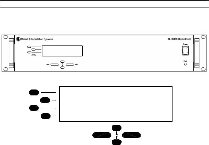
User Controls, indications & connectors
Front plate layout
The front plate layout of the CU 6010 Central Unit consists of a large illuminated LCD display and 8 buttons for setting up/controlling the system:
Details of display
-Audio Control -Delegate setup -Interpreter setup -Units info
MENU |
ENTER |
Front plate controls
The CU 6010 Central unit features the following controls and display:
Power switch
Switches power on to the whole system. When power is switched ON at the CU 6010 any connected EX 6010 Extension Units will automatically be powered up. An indication in the switch is lighting, when power is switched ON
Fault LED
This indication lights up, if the internal power supply is malfunctioning i.e. because of overheating or overload of a chain.
The Fault LED will always light up some seconds after the unit is switched on caused by the delayed switching on of the four supplies.
As a warning the light is flashing at an internal
temperature above 45°C. At a temperature above 55°C or if one of the DCS-LAN outputs is
supplying no voltage, the LED is lighting constantly.
Please note that the maximum ambient temperature for the CU 6010 is 40 deg. Celsius.
LCD Display
This display is used for information purposes and set-up purposes.
10 |
Manual 01 18 04438 |
|
Danish Interpretation Systems |
User Manual |
Buttons |
‘-‘ |
The buttons below and to the left of the display are used when stepping through the different menus and for setting up the system:
∙Four select buttons
Four buttons placed on the left-hand side of the display. Each button is associated with a line pointing towards a text line in the display. This indicates, that pushing the button ‘selects’ the functionality.
∙Enter button
The Enter button is used, when a selection is made in the Main Menu. Pressing the Enter button concludes the selection made, and at the same time it indicates a confirmation of the possible changes made within the selection. The Menu system returns to the previous menu. Notice, that some changes are applied immediately, and confirmation is thus not required.
∙Menu button
The Menu button is also used, when a selection is made in the Main Menu. The Menu button concludes the selection, but in contrast to the Enter button, the Menu button does not confirm a possible change made within the selection. Instead, the Menu system returns to the previous menu without confirming changes, if confirmation is required.
∙Up (▲) and Down (▼) buttons
The Up and Down buttons are used to scroll through menu items, or to increase/decrease values within a selection.
Symbols
The following symbols are used on the LCD display:
The dash symbol (‘-‘) preceding a line of text identifies a submenu or a changeable parameter. The submenu or parameter can be selected by pressing the corresponding select button.
‘>’
The ‘>’ symbol preceding a line of text identifies a selected parameter. The parameter can be changed by pressing the up and down buttons. The ‘>’ symbol is shown as long as the value of the parameter currently used is the same as the value shown in the display.
‘*’
The star symbol ‘*’ preceding a line of text identifies a selected parameter, where the value has been changed, but not yet confirmed. The changed value can be confirmed by pressing the Enter button, or it can be dismissed by pressing the Menu button.
‘▲▼’
The up and down symbols shown in the right side of the display (up is shown in the first line and down is shown in the last line) indicates that the current menu consists of more than 4 menu items. It is therefore necessary to use the up and down buttons to scroll through menu items.
Indications
Cursor
The cursor is used on the LCD display to indicate, when a value is being changed. For a parameter that is subject to a change, the cursor is placed at the value of the parameter, indicating that it is about to be changed.
Manual 01 18 04438 |
11 |
|
Danish Interpretation Systems |
User Manual |
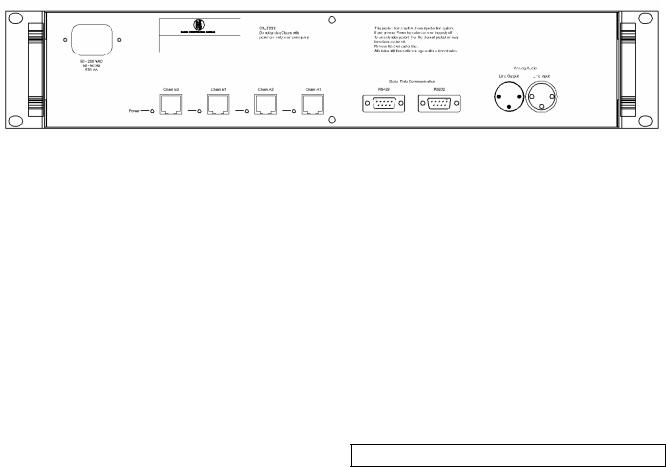
Back Panel Layout
Back Panel Connectors
Mains Power connector
Connection for mains power. See specs.
Analog Audio Line input
XLR Input connector.
For connection of external Line input signal i.e. the Floor (Speaker) signal from another Conference Microphone System or audio mixers. See specs.
Analog Audio Line output.
XLR Output connector.
This connector carries the “Floor” signal. It is us ed either for recording purposes or for feeding signal to an external loudspeaker system. See specs.
Serial Data Communication RS232
D-Sub9 connector
RS232 Serial connection for communication to PC etc. Either the RS232 or the RS422 can be used.
Serial Data Communication RS422
D-Sub 9 connector
RS422 Serial connection for communication to PC etc. Either the RS232 or the RS422 can be used.
Chain A1 & A2
RJ45 connector, 2 pieces
DCS-LAN connectors for connection to DM/CM 6xxx, IS 6032, IS 6132, CS 6032, EX 6010, AO 6004/6008 etc. For connecting Interpreter Sets for up to 16 languages. If more languages are required,
Interpreter sets for those languages have to be connected to Chain B1 or B2.
Chain B1 & B2
RJ45 connector, 2 pieces
DCS-LAN connectors for connection to DM/CM 6xxx, IS 6032, IS 6132, CS 6032, EX 6010, AO 6004/6008 etc. For connecting Interpreter Sets for up to 16 languages. If more languages are required, Interpreter sets for those languages have to be connected to Chain A1 or A2.
Power LED’s
Those LED’s light up when Power is available on the connector next to the LED and only if the voltage is over 24V (not overloaded).
System settings
Control of the system settings is done through selections made in the main menu. Pressing the Menu button will show the Main menu, which comprises the following entries:
∙Audio control
∙Delegate setup
∙Interpreter setup
∙Ambient Microphone
∙Units info
∙RS232 setup
∙Security setup
∙Configuration
∙License info
∙Firmware info
12 |
Manual 01 18 04438 |
|
 Loading...