


 Loading...
USER GUIDE
BUSINESS SERIES
Wireless-G Business
Ethernet Bridge
Model: WET200
About This Guide
About This Guide
Icon Descriptions
While reading through the User Guide you may see various icons that call attention to specific items. Below is a description of these icons:
NOTE: This check mark indicates that there is a note of interest and is something that you should pay special attention to while using the product.
WARNING: This exclamation point indicates that there is a caution or warning and it is something that could damage your property or product.
WEB: This globe icon indicates a noteworthy website address or e-mail address.
Online Resources
Website addresses in this document are listed without http:// in front of the address because most current web browsers do not require it. If you use an older web browser, you may have to add http:// in front of the web address.
Resource |
Website |
|
|
Linksys |
www.linksys.com |
Linksys International |
www.linksys.com/international |
Glossary |
www.linksys.com/glossary |
Network Security |
www.linksys.com/security |
|
|
Copyright and Trademarks
Linksys, Cisco and the Cisco Logo are registered trademarks or trademarks of Cisco Systems, Inc. and/or its affiliates in the U.S. and certain other countries. Copyright © 2008 Cisco Systems, Inc. All rights reserved. Other brands and product names are trademarks or registered trademarks of their respective holders.
Wireless-G Business Ethernet Bridge |
ii |

Table of Contents
Chapter 1: Introduction |
|
|
|
|
|
|
|
|
|
|
1 |
Chapter 2: Planning Your Wireless Network |
|
|
|
|
|
|
2 |
||||
Network Topology . . . . . . . . . . . |
. . . . . . |
2 |
|||||||||
Network Layout |
|
|
|
|
|
|
|
|
|
|
2 |
Example of WET200 in Infrastructure Mode . |
. |
. |
. . |
. |
. |
. |
. . . . 2 |
||||
Example of WET200 in Ad-Hoc Mode . . . |
. |
. . |
. . |
. |
. |
. |
. 3 |
||||
Chapter 3: Product Overview |
|
|
|
|
|
|
|
|
|
|
4 |
Front Panel |
|
|
|
|
|
|
|
|
|
|
4 |
Back Panel . . . . . . . . . |
. |
. |
. . . . . . . . . |
. 4 |
|||||||
Chapter 4: Installation |
|
|
|
|
|
|
|
|
|
|
5 |
Overview |
|
|
|
|
|
|
|
|
|
|
5 |
Connection . . . . . . . . |
. . |
. |
. . . . . . . . |
. 5 |
|||||||
Power over Ethernet |
|
|
|
|
|
|
|
|
|
|
5 |
Power Adapter . . . . . . . . . . . |
. . . . . |
. 5 |
|||||||||
Placement Options . . . . . . . . . . . |
. . . . . |
. 5 |
|||||||||
Stand Option . . . . . . . . . . . |
. . . . . . |
5 |
|||||||||
Wall-Mount Option . . . . . . . . . |
. |
. |
. . . |
. 6 |
|||||||
Chapter 5: Quick Configuration Overview |
|
|
|
|
|
|
|
7 |
|||
Overview |
|
|
|
|
|
|
|
|
|
|
7 |
Accessing the Web-Based Utility . . . . . |
. |
. . |
. . |
. |
. 7 |
||||||
Navigating the Web-Based Utility . . . . . |
. |
. |
. . |
. |
. |
. 7 |
|||||
Setup . . . . . . . . . |
. |
. |
. . . . . . . . . |
. 7 |
|||||||
Wireless |
|
|
|
|
|
|
|
|
|
|
7 |
Switch |
|
|
|
|
|
|
|
|
|
|
8 |
Administration . . . . . . . . . . . |
. . . . . |
. 8 |
|||||||||
System Status . . . . . . . . . . . |
. . . . . . |
8 |
|||||||||
Chapter 6: Advanced Configuration |
|
|
|
|
|
|
|
9 |
|||
Setup . . . . . . . . . . . |
. . . . . . . . . . . |
. 9 |
|||||||||
Wireless |
|
|
|
|
|
|
|
|
|
|
10 |
Wireless > Basic Settings . . . . . . . |
. |
. |
. . |
. |
10 |
||||||
Wireless > Wireless Security . . . . . |
. |
. . |
. . |
. |
. 11 |
||||||
Wireless > Advanced Settings |
|
|
|
|
|
|
|
|
|
13 |
|
Switch |
|
|
|
|
|
|
|
|
|
|
13 |
Switch > Port Management . . . . . |
. |
. . |
. . |
. |
. 13 |
||||||
Switch > Port Mirroring |
|
|
|
|
|
|
|
|
|
|
14 |
Switch > VLAN |
|
|
|
|
|
|
|
|
|
|
14 |
Switch > MAC Based ACL |
|
|
|
|
|
|
|
|
|
|
16 |
Switch > QoS . . . . . . . . . . . |
. . . . . . |
17 |
|||||||||
Switch > Spanning Tree |
|
|
|
|
|
|
|
|
|
|
17 |
Wireless-G Business Ethernet Bridge |
i |

Table of Contents
Switch > MAC Table . . . . . . . |
. |
. |
. |
. |
. |
. |
. |
18 |
|||
Administration . . . . . . . . . . . |
. |
. . . . . |
. |
18 |
|||||||
Administration > Password . . . . |
. |
. |
. |
. |
. |
. . |
. |
18 |
|||
Administration > Web Access . . . |
. |
. |
. |
. |
. |
. . |
. |
. |
18 |
||
Administration > SNMP |
|
|
|
|
|
|
|
|
|
|
19 |
Administration > Configuration Management . . . . . . . . |
. . . . 19 |
||||||||||
Administration > Factory Defaults . |
. |
. |
. |
. |
. |
. . |
. |
. . . |
19 |
||
Administration > Firmware Upgrade . . . . . . . . . . . . |
20 |
||||||||||
System Status |
|
|
|
|
|
|
|
|
|
|
20 |
System Status > System Status . . |
. . |
. |
. |
. |
. |
. . |
. |
. |
20 |
||
System Status > Wireless Status |
|
|
|
|
|
|
|
|
|
|
20 |
System Status > Port Statistics . . |
. . |
. |
. |
. |
. |
. . |
. |
. |
21 |
||
Appendix A: Wireless Security Checklist |
|
|
|
|
|
|
|
|
|
22 |
|
General Network Security Guidelines |
|
|
|
|
|
|
|
|
|
|
22 |
Additional Security Tips . . . . . . . |
. |
. |
. |
. |
. |
. |
. |
22 |
|||
Appendix B: Glossary |
|
|
|
|
|
|
|
|
|
|
23 |
Appendix C: Specifications |
|
|
|
|
|
|
|
|
|
|
27 |
Appendix D: Warranty Information |
|
|
|
|
|
|
|
|
|
|
28 |
Appendix E: Regulatory Information |
|
|
|
|
|
|
|
|
|
|
29 |
FCC Statement . . . . . . . . . . . |
. |
. . . . . |
. |
29 |
|||||||
FCC Radiation Exposure Statement . . |
. . |
. |
. |
. |
. |
. . |
. |
. |
29 |
||
Safety Notices |
|
|
|
|
|
|
|
|
|
|
29 |
Industry Canada Statement . . . . . . |
. |
. |
. |
. |
. |
. |
|
. |
29 |
||
Industry Canada Radiation Exposure Statement: |
|
|
|
|
|
29 |
|||||
Avis d’Industrie Canada |
|
|
|
|
|
|
|
|
|
|
30 |
Avis d’Industrie Canada concernant l’exposition aux radiofréquences : |
|
30 |
|||||||||
Wireless Disclaimer . . . . . . . . . |
. |
. |
. . . . |
. |
30 |
||||||
Avis de non-responsabilité concernant les appareils sans fil . . . . |
. . . . . . . |
. 30 |
|||||||||
User Information for Consumer Products Covered by EU Directive 2002/96/EC on Waste |
|||||||||||
Electric and Electronic Equipment (WEEE) |
|
|
|
|
|
|
|
|
|
31 |
|
Appendix F: Contact Information |
|
|
|
|
|
|
|
|
|
|
35 |
Wireless-G Business Ethernet Bridge |
ii |

Chapter 1 |
Introduction |
Chapter 1:
Introduction
Thank you for choosing the Wireless-G Business Ethernet Bridge.
The Linksys WET200 Wireless Bridge seamlessly bridges separate Ethernet networks together wirelessly and is ideal for small businesses with offices and resources that are in different office suites of a building or a closely adjacent building. The WET200 is a Power over Ethernet (PoE) end device so it can be installed anywhere an Ethernet cable can be run if there is not ready access to a power outlet. PoE enables delivery of both data and power to the WET200. An AC adapter is also included if the device installation site has a power outlet nearby.
Advanced security features include Wi-Fi Protected Access™ (WPA2 Enterprise) with up to 256-bit AES encryption using EAP (Extensible Authentication Protocol) giving small businesses the protection they need to communicate and transfer data securely. The integrated QoS features provide consistent voice and video quality on both the wired and wireless networks, enabling the deployment of business qualilty VoIP and video applications.
Additional support for VLANs, SNMP, Spanning Tree, and Port Mirroring make this an ideal solution for network administrators to incorporate into larger organizations.
Wireless-G Business Ethernet Bridge |
1 |
Chapter 2
Chapter 2:
Planning Your Wireless
Network
Network Topology
A wireless network is a group of computers, each equipped with one or more wireless adapters. Computers in a wireless network must be configured to share the same radio channel to talk to each other. Several PCs equipped with wireless cards or adapters can communicate with each other to form an ad-hoc network without the use of an access point.
Linksys wireless adapters also provide access to a wired network when using an access point or wireless router. An integrated wireless and wired network is called an infrastructurenetwork.EachwirelessPCinaninfrastructure network can talk to any computer in a wired or wireless network via the access point or wireless router.
An infrastructure configuration extends the accessibility of a wireless PC to a wired network, and may double the effective wireless transmission range for two wireless adapter PCs. Since an access point is able to forward data within a network, the effective transmission range in an infrastructure network may be doubled (depending on antenna characteristics).
Network Layout
The Wireless-G Business Ethernet Bridge can be used in either Infrastructure mode or Ad-Hoc mode. In Infrastructure mode, the WET200 can be used to bridge a separate Ethernet segment wirelessly to the company network backbone. In Ad-Hoc mode, the WET200 communicates directly with other wireless devices, much like a wireless client card. The WET200 has been designed for use with 802.11g and 802.11b products, such as the WAP200 Wireless-G Access Point, in addition to various wireless adapters for notebook and desktop PC.
Go to the Linksys website at www.linksys.com for more information about wireless products.
Planning Your Wireless Network
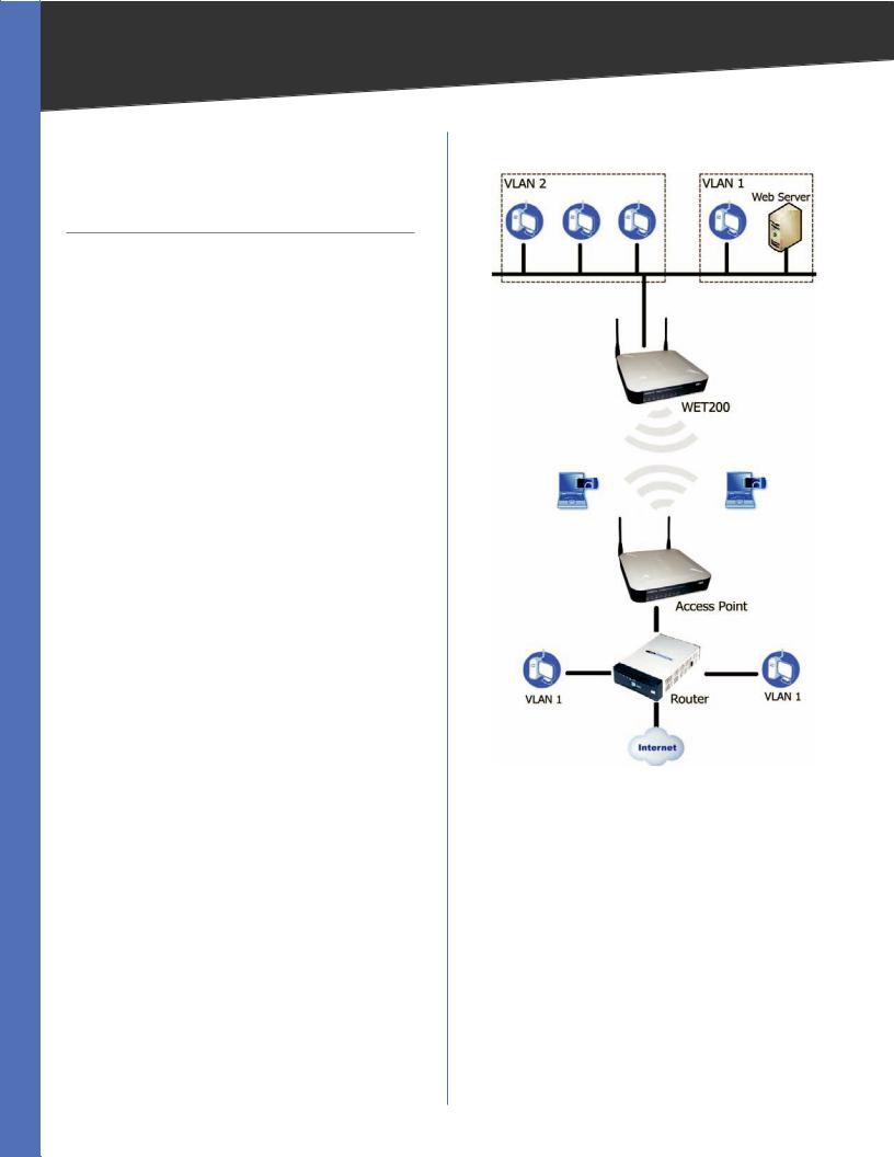
Example of WET200 in Infrastructure Mode
Example of WET200 in Infrastructure Mode
The above diagram shows a typical infrastructure wireless network setup where the WET200 is being used to manage multiple VLANs, with one VLAN connected wirelessly to the company network and Internet. In this example, the WET200 is connected to a wireless Access Point, which is in turn connected to the network backbone.
Wireless-G Business Ethernet Bridge |
2 |
Chapter 2 |
Planning Your Wireless Network |
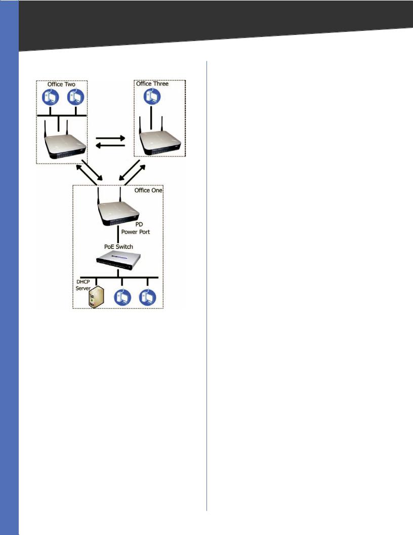
Example of WET200 in Ad-Hoc Mode
Example of WET200 in Ad-Hoc Mode
TheWET200 can also be used to quickly set up a temporary network, as shown above. The diagram shows three wired networks, Office One, Office Two, and Office Three, each with a direct connection to the other wired networks via an Ad-Hoc network connection. The Bridge in Office One is connected to a Linksys switch that provides power to the Bridge. In this example, a DHCP server is set up to assign IP addresses automatically, since the WET200 does not have a built-in DHCP server. Alternatively, static IP addresses can be used.
Wireless-G Business Ethernet Bridge |
3 |
Chapter 3
Chapter 3:
Product Overview
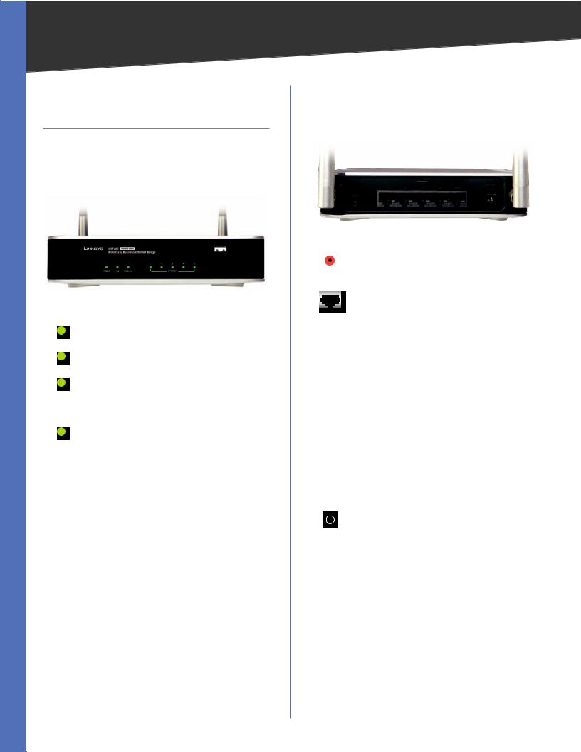
Front Panel
The Bridge’s LEDs, where information about network activity is displayed, are located on the front panel.
Front Panel
POWER (Green) Lights up when the Bridge is powered on.
PoE (Green) Lights up when power is being supplied through Ethernet cable.
WIRELESS (Green) Lights up when the wireless module is active on the Bridge. Flashes to indicate that the Bridge is actively sending or receiving data from a wireless device.
ETHERNET (1-5) Lights up to indicate a functional 10/100 Mbps network link through the corresponding port (1 through 5) with an attached device. Blinks to indicate that the Bridge is actively sending or receiving data over that port.
Product Overview
Back Panel
The reset button, the Ethernet ports, and the power port are located on the back panel of the Bridge.
Back Panel
RESET Press and hold the Reset button for approximately ten seconds to reset the Bridge to the factory default settings.
ETHERNET 1-5 These RJ-45 ports support network speeds of either 10 Mbps or 100 Mbps, and can operate in half and full-duplex modes. Auto-sensing technology enables each port to automatically detect the speed of the device connected to it (10 Mbps or 100 Mbps), and adjust its speed and duplex accordingly.
Port 5 also supports the IEEE 802.3af Power- over-Ethernet (PoE) PD standard that enables DC power to be supplied to the Bridge using wires in the connecting twisted-pair cable. This allows the Bridge to draw power directly from the Ethernet cable without requiring its own separate power source. If a PoE power source is not available, you can use the supplied AC power adaptor.
To connect a device to a port, you need to use Category 5 (or better) network cable.
POWER The Power port is where you connect the AC power. This port is not used if you are using Power over Ethernet (PoE) to supply power through the Ethernet cable.
Wireless-G Business Ethernet Bridge |
4 |

Chapter 4
Chapter 4:
Installation
Overview
This chapter explains how to place and connect the Bridge. Depending on your application, you might want to set up the device first before mounting the device. Refer to “Chapter 6: Advanced Configuration”.
Connection
There are two ways to install the Bridge: using Power over Ethernet (PoE), or using the supplied power adapter. Follow the appropriate procedure below.
Power over Ethernet
1.Connect one end of an Ethernet network cable to the LAN port on your PC, then connect the other end to Ethernet port 1, 2, 3, or 4 on the Bridge.
Connect the Bridge to a PC
2.Connect one end of an Ethernet network cable to your PoE-equipped network switch or router, and connect the other end of the cable to port 5 on the Bridge.
Connect the PoE Cable
3.The Power LED on the front panel lights up green as soon as the power is connected properly.”
Proceed to the section, “Placement Options.”
Installation
Power Adapter
1.Connect one end of an Ethernet network cable to the LAN port on your PC, then connect the other end to Ethernet port 1, 2, 3, 4, or 5 on the Bridge.
Connect the Bridge to a PC
2.Connect the included power adapter to the Bridge’s Power port. Then plug the power adapter into an electrical outlet.
Connect the Power Adapter
3.The Power LED on the front panel lights up green as soon as the power is connected properly.”
Proceed to the following section, “Placement Options.”
Placement Options
There are three ways to place the Bridge. The first way is to place it on a horizontal surface, so that it sits securely on its four rubber feet. The second way is to stand the Bridge upright on a horizontal surface by attaching the included stands. The third way is to mount it on a wall. The stand and wall-mount options are explained in further detail below.
Stand Option
1.Locate the Bridge’s left side panel.
2.The Bridge includes two stands. Position one of the stands with its two large prongs facing outward, then insert the short prongs into the small slots in the
Wireless-G Business Ethernet Bridge |
5 |

Chapter 4 |
Installation |
Bridge, and push the stand upward until it snaps into place. Repeat this step with the other stand.
Large Prongs
Stand Installation
Proceed to “Chapter 6: Advanced Configuration,” for directions on how to set up the Bridge.
Wall-Mount Option
1.On the Bridge’s back panel are two crisscross wallmount slots.
2-15/16"
Wall-Mount Slots on Bridge’s Back Panel
2.Determine where you want to mount the Bridge, and install two screws that are 2-15/16” apart.
3.Line up the Bridge so that the wall-mount slots line up with the two screws.
4.Place the wall-mount slots over the screws and slide the Bridge down until the screws fit snugly into the wall-mount slots.
Proceed to “Chapter 6: Advanced Configuration,” for directions on how to set up the Bridge..
Wireless-G Business Ethernet Bridge |
6 |
Chapter 5
Chapter 5:
Quick Configuration
Overview
Overview
The Ethernet switch of the WET200 is designed to be functional right out of the box with the default settings. In order to use the wireless bridge function, however, you must first perform a minimal configuration on the Bridge so that it can find and communicate with the access point. The Bridge can be configured through your web browser with the web based utility. This chapter explains how to use the utility.
The utility can be accessed via web browsers, such as Microsoft Internet Explorer or Mozilla Firefox through the use of a computer that is networked with the Bridge.
For a basic network setup, most users only have to use the following screens of the Utility:
•• Setup The Setup screen is the first screen displayed. Enter your basic network settings (IP address) here to allow your PC to access the web-based utility.
NOTE: If your network backbone has a DHCP server, you must first create a wireless connection between the bridge and the access point before you attempt to configure DHCP. Otherwise, the bridge will not be able to obtain an IP address and the web-based utility will be inaccessible. For information on how to create the wireless connection, see Chapter 6, “Advanced Configuration.”
•• Password Click the Administration tab, then select the Password sub tab. The Bridge’s default password is admin. To secure the Bridge, change the Password from its default.
•• Wireless Click the Wireless tab to access the Wireless screen to configure a wireless connection. This is most easily done using the Site Survey feature. Click Site Survey, then select your wireless network’s access point from the list. If you are prompted for security settings, enter the requested information (such as passphrase or shared secret), The wireless bridge will now be connected to the access point.
Quick Configuration Overview
Accessing the Web-Based Utility
To access the web-based utility, perform these steps:
1.Configure your PC with a static IP address in the same subnet as the Bridge’s default IP address, 192.168.1.226. If a DHCP server is to be connected to the switch, configure it to assign the IP address in subnet 192.168.1.0/24. Your PC will get an IP address in the subnet through the DHCP.
2.Launch your web browser, such as Internet Explorer or Mozilla Firefox, and enter the Bridge’s default IP address, 192.168.1.226, in the Address field. Press the
Enter key.
3.Enter admin in the User Name field. The first time you open the web-based utility, use the default password, admin. (You can set a new password from
Administration > Password) Then click OK.
When you are finished setting up the Bridge’s IP address, either by manually assigning it a new IP address or by configuring it to use DHCP, move your Bridge to the desired network. You will have to use the new IP address the next time you access the web-based utility.
Navigating the Web-Based Utility
The web-based utility consists of the following five main tabs: Setup, Wireless, Switch, Administration, and
System Status. Additional screens (sub tabs) will be available from most of the main tabs.
The following briefly describes the main and sub tabs of the Utility.
Setup
Setup Enter the Host Name and IP Address settings on this screen.
Wireless
You use the Wireless tabs to enter a variety of wireless settings for the Bridge.
Basic Settings Choose the wireless network mode (e.g. wireless-G), wireless channel, network type, and SSID configuration on this screen.
WirelessSecurity UsethisscreentoconfiguretheBridge’s security settings including security mode, authentication, and encryption information.
Advanced Settings This screen allows you to configure the Bridge’s more advanced wireless settings such as Transmission Rate, RTS Threshold, etc.
Wireless-G Business Ethernet Bridge |
7 |

Chapter 5
Switch
You use the Switch tabs to enter settings that are used by the Bridge’s switching features.
Port Management Use this screen to configure the Administrative Status, Flow Control, Link, Duplex, and Speed of the Bridge’s ports.
Port Mirroring Configure Port MIrroring on this screen.
VLAN This screen lets you configure Port-Based or 802.1Q VLAN settings.
MAC Based ACL Use this screen to create a MAC-based Access List (ACL) to control which MAC addresses can access your network.
QoS On this screen you configure the Quality of Service (QoS) settings on the Bridge’s ports.
Spanning Tree This screen is used to configure the Spanning Tree Protocol settings on the Bridge.
MAC Table Use this screen to configure the Bridge’s MAC address table settings.
Administration
You use the Administration tabs to manage the Bridge. Password Use this screen to change the password.
SNMP This screen is used to enter the Simple Network Management Protocol (SNMP) settings.
Config Management Use this screen to save the Bridge’s configuration to a file, and to restore the configuration from a file.
Factory Default Use this screen to reset the Bridge to its factory default settings.
Firmware Upgrade Upgrade the Bridge’s firmware on this screen.
System Status
The System Status tab lets you view status information for your local network, wireless networks, and network performance.
System Status This screen displays basic system information, including system up time, firmware version, MAC address, and LAN settings.
Wireless Status This screen displays wireless network settings including SSID, network type, wireless mode and channel, security mode, transmit rate, and link quality.
Port Statistics This screen displays the current traffic statistics of the Bridge’s Wireless and LAN ports.
Quick Configuration Overview
Wireless-G Business Ethernet Bridge |
8 |
Loading...