


 ®
®
A Division of Cisco Systems, Inc.
24-Port 10/100 + 2-Port Gigabit Switch
with WebView and Power over Ethernet User Guide
 WIRED
WIRED
Model No. SRW224P

24-Port 10/100 + 2-Port Gigabit Switch with Webview and Power over Ethernet
Copyright and Trademarks
Specifications are subject to change without notice. Linksys is a registered trademark or trademark of Cisco Systems, Inc. and/or its affiliates in the U.S. and certain other countries. Copyright © 2005 Cisco Systems, Inc. All rights reserved. Other brands and product names are trademarks or registered trademarks of their respective holders.
WARNING: This product contains chemicals, including lead, known to the State of California to cause cancer, and birth defects or other reproductive harm. Wash hands after handling.
How to Use This User Guide
This User Guide has been designed to make understanding networking with the Switch easier than ever. Look for the following items when reading this User Guide:
This checkmark means there is a note of interest and is something you should pay special attention to while using the Switch.
This exclamation point means there is a caution or warning and is something that could damage your property or the Switch.
This question mark provides you with a reminder about something you might need to do while using the Switch.
In addition to these symbols, there are definitions for technical terms that are presented like this:
word: definition.
Also, each figure (diagram, screenshot, or other image) is provided with a figure number and description, like this:
Figure 0-1: Sample Figure Description
Figure numbers and descriptions can also be found in the “List of Figures” section in the “Table of Contents”.
SRW224P-UG-51008 KL
24-Port 10/100 + 2-Port Gigabit Switch with Webview and Power over Ethernet
Table of Contents
Chapter 1: Introduction |
1 |
Welcome |
1 |
What’s in this Guide? |
2 |
Chapter 2: Getting to Know the Switch |
3 |
The Front Panel |
3 |
The Back Panel |
4 |
The Side Panel |
4 |
RJ-45 Ports |
5 |
The Gigabit Expansion Ports |
5 |
The Console Port |
5 |
Chapter 3: Connecting the Switch |
6 |
Overview |
6 |
Pre-Installation Considerations |
7 |
Hardware Installation |
8 |
Placement Options |
8 |
Uplinking the Switch |
9 |
Chapter 4: Configuration using the Console Interface |
10 |
Overview |
10 |
Configuring the Switch through the Console Interface |
11 |
Chapter 5: Configuring the Switch through the Web Utility |
24 |
Overview |
24 |
System Information |
25 |
IP Config |
31 |
Switch Config |
33 |
QoS |
43 |
DiffServ |
50 |
Security |
56 |
SNTP |
65 |
Statistics |
66 |
PoE |
68 |
Spanning Tree |
71 |
SNMP |
75 |
IGMP |
76 |
Maintenance |
80 |
24-Port 10/100 + 2-Port Gigabit Switch with Webview and Power over Ethernet |
|
Help |
82 |
Appendix A: Fast Ethernet and Gigabit Ethernet |
83 |
About Fast Ethernet |
83 |
About Gigabit Ethernet |
83 |
Appendix B: Cabling |
84 |
Overview |
84 |
Twisted Pair Cabling |
84 |
Fiber Optic Cabling |
84 |
Appendix C: Glossary |
85 |
Appendix D: Specifications |
88 |
Appendix E: Warranty Information |
89 |
Appendix F: Regulatory Information |
90 |
Appendix G: Contact Information |
96 |
24-Port 10/100 + 2-Port Gigabit Switch with Webview and Power over Ethernet
List of Figures
Figure 2-1: Front Panel |
3 |
Figure 2-2: Back Panel |
4 |
Figure 2-3: Side Panel |
4 |
Figure 3-1: Typical Network Configuration |
6 |
Figure 3-2: Attaching the Switch’s Rubber Feet |
8 |
Figure 3-3: Attaching Brackets to the Switch |
9 |
Figure 3-4: Mounting the Switch |
9 |
Figure 4-1: Finding Hyperterminal |
10 |
Figure 4-2: Connection Description |
10 |
Figure 4-3: Password Screen |
10 |
Figure 4-4: COM1 Properties |
11 |
Figure 4-5: Login |
11 |
Figure 4-6: Switch Main Menu |
12 |
Figure 4-7: System Configuration Menu |
12 |
Figure 4-8: System Information |
13 |
Figure 4-9: Versions |
13 |
Figure 4-10: General Information |
13 |
Figure 4-11: Serial Port Configuration |
14 |
Figure 4-12: CPU Performance |
14 |
Figure 4-13: User and Password Settings |
15 |
Figure 4-14: IP Configuration |
16 |
Figure 4-15: IP Address Configuration Screen |
16 |
Figure 4-16: HTTP |
16 |
Figure 4-17: SNMP |
17 |
Figure 4-18: Network Configuration/PING |
17 |
Figure 4-19: File Management |
18 |
Figure 4-20: Restore System Default Settings |
19 |
Figure 4-21: Reboot System |
19 |
Figure 4-22: Back to Main Menu |
20 |
Figure 4-23: Port Status |
21 |
24-Port 10/100 + 2-Port Gigabit Switch with Webview and Power over Ethernet
Figure 4-24: Port Configuration |
21 |
Figure 4-25: PoE Main Menu |
22 |
Figure 4-26: Power Configuration |
22 |
Figure 4-27: Power Port Status |
22 |
Figure 4-28: Power Port Configuration |
23 |
Figure 4-29: Logout |
23 |
Figure 5-1: Address Field |
24 |
Figure 5-2: Password Screen |
24 |
Figure 5-3: Sys. Info - System Description |
24 |
Figure 5-4: Sys. Info - System Information |
25 |
Figure 5-5: Sys. Info - System Mode |
26 |
Figure 5-6: Sys. Info - Forwarding Database |
27 |
Figure 5-7: Dynamic Address Screen |
28 |
Figure 5-8: Static Address Screen |
28 |
Figure 5-9: Sys. Info - Time Synchronization Screen |
29 |
Figure 5-10: Sys. Info - CPU Performance |
30 |
Figure 5-11: Sys. Info - Logout |
30 |
Figure 5-12: IP Config - IP Address |
31 |
Figure 5-13: Switch Config - Port Configuration |
33 |
Figure 5-14: Edit Port Configuration Screen |
34 |
Figure 5-15: Switch Config - VLAN |
36 |
Figure 5-16: Adding/Editing VLAN Screen |
37 |
Figure 5-17: Switch Config - VLAN Port |
38 |
Figure 5-18: Switch Config - LAG Configuration |
39 |
Figure 5-19: Create LAG Screen |
40 |
Figure 5-20: LAG Broadcast Control Screen |
40 |
Figure 5-21: VLAN LAG Configuration Screen |
40 |
Figure 5-22: Switch Config - Port Mirroring |
41 |
Figure 5-23: Switch Config - LACP |
42 |
Figure 5-24: LACP Membership Screen |
42 |
Figure 5-25: QoS - CoS Settings |
44 |
Figure 5-26: QoS - Queue Settings |
45 |
Figure 5-27: QoS - CoS to Queue |
45 |
24-Port 10/100 + 2-Port Gigabit Switch with Webview and Power over Ethernet
Figure 5-28: QoS - IP Precedence/DSCP |
46 |
Figure 5-29: QoS - IP Port |
47 |
Figure 5-30: QoS - ACL Priority |
48 |
Figure 5-31: QoS - Rate Limit |
49 |
Figure 5-32: DiffServ - Diffserv Class Map |
51 |
Figure 5-33: DiffServ Class Map - Setting Rules |
51 |
Figure 5-34: DiffServ Class Map - Adding a Class |
52 |
Figure 5-35: DiffServ - Diffserv Policy Map |
53 |
Figure 5-36: DiffServ Policy Map - Adding a Policy |
53 |
Figure 5-37: DiffServ Policy Map - Setting Rules |
54 |
Figure 5-38: DiffServ - Diffserv Service Policy |
55 |
Figure 5-39: Security - ACL Conf |
56 |
Figure 5-40: ACL Conf - Adding/Editing Standard ACL |
57 |
Figure 5-41: ACL Conf - Adding/Editing Extended ACL |
57 |
Figure 5-42: ACL Conf - Adding/Editing MAC ACL |
59 |
Figure 5-43: Security - ACL Port Binding |
60 |
Figure 5-44: Security - 802.1x Users |
61 |
Figure 5-45: Security - 802.1x Port Conf |
62 |
Figure 5-46: Security - RADIUS Server |
62 |
Figure 5-47: Security - Port Security |
63 |
Figure 5-48: Security - Storm Control |
63 |
Figure 5-49: Security - HTTPS Settings |
64 |
Figure 5-50: Security - System Password |
64 |
Figure 5-51: SNTP - Global Settings |
65 |
Figure 5-52: Statistics - Interface Statistics |
66 |
Figure 5-53: Statistics - Etherlike Statistics |
67 |
Figure 5-54: Statistics - RMON Statistics |
67 |
Figure 5-55: PoE - Power Config |
68 |
Figure 5-56: PoE - Power Port Config |
69 |
Figure 5-57: PoE - Power Port Status |
69 |
Figure 5-58: PoE - Power Status |
70 |
Figure 5-59: Spanning Tree - Information |
72 |
Figure 5-60: Spanning Tree - Configuration |
73 |
24-Port 10/100 + 2-Port Gigabit Switch with Webview and Power over Ethernet
Figure 5-61: Spanning Tree - Port/LAG Info |
73 |
Figure 5-62: Spanning Tree - Information |
74 |
Figure 5-63: SNMP - SNMP Config |
75 |
Figure 5-64: IGMP - IGMP Conf |
77 |
Figure 5-65: IGMP - IGMP Router Info |
78 |
Figure 5-66: IGMP - IGMP Router Conf |
78 |
Figure 5-67: IGMP - IP Multicast Reg Table |
79 |
Figure 5-68: IGMP - IGMP Member Conf |
79 |
Figure 5-69: Maintenance - Reset |
80 |
Figure 5-70: Maintenance - File Download |
80 |
Figure 5-71: Maintenance - File Upload |
81 |
Figure 5-72: Maintenance - Restore Defaults |
81 |
Figure 5-73: Maintenance - Save Config |
81 |
Figure 5-74: Maintenance - Integrated Cable Test |
82 |
Figure 5-75: Help |
82 |
24-Port 10/100 + 2-Port Gigabit Switch with Webview and Power over Ethernet
Chapter 1: Introduction
Welcome
Thank you for choosing the 24-port 10/100 + 2-Port Gigabit Switch with WebView and Power over Ethernet. This
Switch will allow you to network better than ever.
This new Linksys rackmount Switch delivers non-blocking, wire speed switching for your 10 and 100 megabit network clients, plus multiple options for connecting to your network backbone. Twenty-four 10/100 ports wire up your workstations, while the two integrated 10/100/1000BaseTX ports connect to other switches and the backbone at Gigabit speeds. And the mini-GBIC ports allow future expansion through alternate transmission media like optical fiber.
All the 10/100 ports on this Switch support IEEE 802.3af standard (802.3af) Power-over-Ethernet (PoE) capabilities. Each port can detect connected 802.3af-compliant network devices, such as IP phones or wireless access points, and automatically supply the required DC power.
The Switch can provide DC power to a wide range of connected devices, eliminating the need for an additional power source and cutting down on the amount of cables attached to each device. Once configured to supply power, an automatic detection process is initialized by the Switch that is authenticated by a PoE signature from the connected device. Detection and authentication prevent damage to non-PoE devices.
The Switch features WebView monitoring and configuration via your web browser, making it easy to manage the 128 VLANs and up to 4 lagging groups. Or if you prefer, you can use the integrated console port to configure the Switch. The non-blocking, wire-speed switching forwards packets as fast as your network can deliver them.
All ports have automatic MDI/MDI-X crossover detection. Each port independently and automatically negotiates for best speed and whether to run in halfor full-duplex mode. Head-of-line blocking prevention keeps your highspeed clients from bogging down in lower-speed traffic and fast store-and-forward switching prevents damaged packets from being passed on into the network.
Use the instructions in this User Guide to help you connect the Switch, set it up, and configure it to bridge your different networks. These instructions should be all you need to get the most out of the 24-port 10/100 + 2-Port Gigabit Switch with WebView and Power over Ethernet.
1
Chapter 1: Introduction
Welcome
24-Port 10/100 + 2-Port Gigabit Switch with Webview and Power over Ethernet
What’s in this Guide?
This user guide covers the steps for setting up and using the Switch.
•Chapter 1: Introduction
This chapter describes the Switch’s applications and this User Guide.
•Chapter 2: Getting to Know the Switch
This chapter describes the physical features of the Switch.
•Chapter 3: Connecting the Switch
This chapter describes how to connect the Switch.
•Chapter 4: Configuration using the Console Interface
This chapter instructs you on how to use the Switch’s console interface for configuring the Switch.
•Chapter 5: Configuring the Switch through the Web Utility
This chapter shows you how to configure the Switch using the Web Utility.
•Appendix A: Fast Ethernet and Gigabit Ethernet
This appendix describes the various types of ethernet.
•Appendix B: Cabling
This appendix discusses different types of cabling.
•Appendix C: Glossary
This appendix gives a brief glossary of terms frequently used in networking.
•Appendix D: Specifications
This appendix provides the Switch’s technical specifications.
•Appendix E: Warranty Information
This appendix supplies the Switch’s warranty information.
•Appendix F: Regulatory Information
This appendix supplies the Switch’s regulatory information.
•Appendix G: Contact Information
This appendix provides contact information for a variety of Linksys resources, including Technical Support.
2
Chapter 1: Introduction
What’s in this Guide?
24-Port 10/100 + 2-Port Gigabit Switch with Webview and Power over Ethernet
Chapter 2: Getting to Know the Switch
The Front Panel
The Switch's LEDs and ports are located on the front panel.
|
Figure 2-1: Front Panel |
LEDs |
|
System |
A green LED indicates that power is being supplied to the Switch. A solid, amber |
|
LED indicates that the Switch’s power-on-self-test (POST) is in progress, but |
|
when this blinks amber that indicates that the POST has failed. |
Link/Act |
A green LED indicates a functional network link through the corresponding port |
|
(1 through 26) with an attached device. A blinking LED indicates that the Switch |
|
is actively sending or receiving data over that port. |
PoE |
A green LED indicates a powered device is connected to the corresponding port |
|
(1 through 24). |
Speed |
A green LED indicates a link to the corresponding port (Gigabit ports 25 and 26) is |
|
operating at 1000Mbps. No light indicates either no link or a link operating at a |
|
speed of 10/100Mbps. |
3
Chapter 2: Getting to Know the Switch
The Front Panel
24-Port 10/100 + 2-Port Gigabit Switch with Webview and Power over Ethernet
Ports
LAN (1-24) |
The LAN ports connect to Ethernet network devices, such as other switches or |
|
routers. |
Gigabit1 (25)/Gigabit 2 (26) The Switch is equipped with two Gigabit RJ-45 ports that are shared with two
|
mini-GBIC ports. If a Gigabit mini-GBIC port is being used, the associated RJ-45 |
|
port cannot be used. They link to high-speed network peripheral system or |
|
clients at speeds of up to 1000Mbps. |
Console |
The Console port is where you connect a serial cable from a PC’s serial port. |
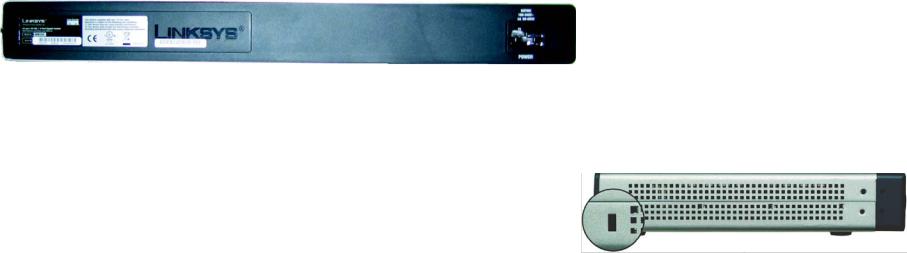
The Back Panel
The power port is located on the back panel.
Figure 2-2: Back Panel
Power |
The Power port is where you will connect the power cord. |
The Side Panel
A security slot, where you can attach a lock to protect the Switch, is located on a side panel.
Chapter 2: Getting to Know the Switch
The Back Panel
Figure 2-3: Side Panel
4
24-Port 10/100 + 2-Port Gigabit Switch with Webview and Power over Ethernet
RJ-45 Ports
The Switch is equipped with 24 auto-sensing RJ-45 ports. These RJ-45 ports support network speeds of either 10Mbps or 100Mbps, and can operate in half and full-duplex modes. Auto-sensing technology enables each port to automatically detect the speed of the device connected to it (10Mbps or 100Mbps), and adjust its speed and duplex accordingly.
The Switch’s RJ-45 ports also support the IEEE 802.3af Power-over-Ethernet (PoE) standard that enables DC power to be supplied to attached devices using wires in the connecting twisted-pair cable. Any 802.3afcompliant device attached to a port can directly draw power from the Switch over the twisted-pair cable without requiring its own separate power source. This capability gives network administrators centralized power control for devices such as IP phones and wireless access points, which translates into greater network availability.
For each attached 802.3af-compliant device, the Switch automatically senses the load and dynamically supplies the required power. The Switch delivers power to a device using the two data wire pairs in the twisted-pair cable. Each port can provide up to 15.4 W of power at the standard -48 VDC voltage.
To connect a device to a port, you will need to use a network cable. You will need to use Category 5 (or better) cable. For more information on twisted-pair cabling, refer to Appendix B: Cabling.
The Gigabit Expansion Ports
The Switch is equipped with two Gigabit Ethernet ports that have shared mini-GBIC ports, which provide for the installation of one expansion module. These ports provide links to high-speed network segments or individual workstations at speeds of up to 1000Mbps (Gigabit Ethernet).
To establish a Gigabit Ethernet connection using a mini-GBIC port, you will need to install an MGBT1, MGBSX2, or MGBLH1 Gigabit expansion module and use Category 5e cabling or fiber optic cabling. For more information on fiber optic cabling, refer Appendix B: Cabling
The Console Port
The Switch is equipped with a serial port labeled CONSOLE (located on the front of the Switch) that allows you to connect to a computer’s serial port (for configuration purposes) using the provided serial cable. You can use HyperTerminal to manage the Switch using the console port.
With this and many other Linksys products, your networking options are limitless. Go to the Linksys website at
www.linksys.com for more information about products that work with the Switch.
5
Chapter 2: Getting to Know the Switch
RJ-45 Ports
24-Port 10/100 + 2-Port Gigabit Switch with Webview and Power over Ethernet
Chapter 3: Connecting the Switch
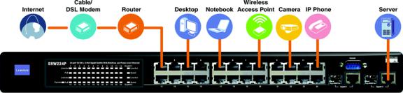
Overview
This chapter will explain how to connect network devices to the Switch. The following diagram shows a typical network configuration.
Figure 3-1: Typical Network Configuration
When you connect your network devices, make sure you don’t exceed the maximum cabling distances, which are listed in the following table:
Maximum Cabling Distances
From |
To |
Maximum Distance |
|
|
|
Switch |
Switch or Hub |
100 meters (328 feet) |
|
|
|
Hub |
Hub |
5 meters (16,4 feet) |
|
|
|
Switch or Hub |
Computer |
100 meters (328 feet) |
|
|
|
*A hub refers to any type of 100Mbps hub. A 10Mbps hub connected to another 10Mbps hub can span up to 100 meters (328 feet).
6
Chapter 3: Connecting the Switch
Overview
24-Port 10/100 + 2-Port Gigabit Switch with Webview and Power over Ethernet
Pre-Installation Considerations
Fast Ethernet Considerations
If you will be using the Switch for Fast Ethernet (100Mbps) applications, you must observe the following guidelines:
Full-Duplex
As previously mentioned, the Switch provides full-duplex support for its RJ-45 ports. Full-duplex operation allows data to be sent and received simultaneously, doubling a port’s potential data throughput.
If you will be using the Switch in full-duplex mode, the maximum cable length using Category 5 cable is 328 feet (100 meters).
Positioning the Switch
Before you choose a location for the Switch, observe the following guidelines:
1.Make sure that the Switch is accessible and that the cables can be connected easily.
2.Keep cabling away from sources of electrical noise, power lines, and fluorescent lighting fixtures.
3.Position the Switch away from water and moisture sources.
4.To ensure adequate air flow around the Switch, be sure to provide a minimum clearance of two inches (50mm).
5.Do not stack free-standing Switches more than four units high.
6.Connect Network Devices
7
Chapter 3: Connecting the Switch
Pre-Installation Considerations
24-Port 10/100 + 2-Port Gigabit Switch with Webview and Power over Ethernet
Hardware Installation
To connect network devices to the Switch, follow these instructions:
1.Make sure all the devices you will connect to the Switch are powered off.
2.Connect a Category 5 Ethernet network cable to one of the numbered ports on the Switch.
3.Connect the other end to a PC or other network device.
4.Repeat steps 2 and 3 to connect additional devices. If 802.3af-compliant PoE devices are connected to the Switch’s 10/100 ports, the Switch automatically supplies the required power.
5.If you are using the Gigabit port, connect a Category 5e Ethernet network cable to the Gigabit port on the Switch, and connect the other end to a Gigabit server or other network device.
6.If you are using a mini-GBIC port, then connect a mini-GBIC module to the mini-GBIC port. For detailed instructions, refer to the module’s documentation.
7.Connect the supplied power cord to the Switch’s power port, and plug the other end into an electrical outlet. When connecting power, always use a surge protector.
8.Power on the devices connected to the Switch. Each active port’s corresponding LED will light up on the Switch.
Placement Options
There are two ways to physically install the Switch, either set the Switch on its four rubber feet for desktop placement or mount the Switch in a standard-sized, 19-inch high rack for rack-mount placement.
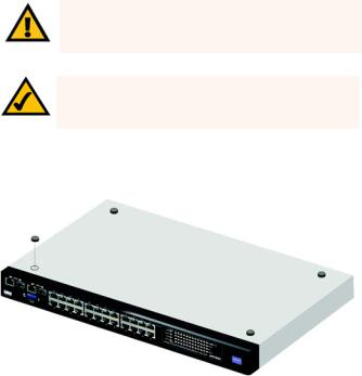
Desktop Placement
1.Attach the rubber feet to the recessed areas on the bottom of the Switch.
2.Place the Switch on a desktop near an AC power source.
3.Keep enough ventilation space for the Switch and check the environmental restrictions mentioned in Appendix D: Specifications as you are placing the Switch.
4.Connect the Switch to network devices according to the Hardware Installation instructions above.
Chapter 3: Connecting the Switch
Hardware Installation
IMPORTANT: Make sure to use the power cord that is supplied with the Switch. Use of a different power cord could damage the Switch.
NOTE: If you need to reset the Switch, remove the power cord from the back of the Switch and then reconnect it.
Figure 3-2: Attaching the Switch’s Rubber Feet
8
24-Port 10/100 + 2-Port Gigabit Switch with Webview and Power over Ethernet
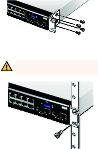
Rack-Mount Placement
To rack-mount the Switch in any standard 19-inch rack, follow the instructions described below.
1.Place the Switch on a hard flat surface with the front panel faced towards your front side
2.Attach a rack–mount bracket to one side of the Switch with the supplied screws.
3.Secure the brackets tightly.
4.Follow the same steps to attach the other bracket to the opposite side.
5.After the brackets are attached to the Switch, use suitable screws to securely attach the brackets to any standard 19-inch rack.
6.Connect the Switch to network devices according to the Hardware Installation instructions above.
Uplinking the Switch
To uplink the Switch, connect one end of a Cat5 (or better) cable into one of the 24 10/100 ports, and then connect the other end of the cable into the peripheral device’s uplink port. MDI/MDIX will automatically detect the speed and cable type.
The hardware installation is complete. Proceed to Chapter 4: Configuration using the Console Interface, for directions on how to set up the Switch.
Chapter 3: Connecting the Switch
Uplinking the Switch
Figure 3-3: Attaching Brackets to the Switch
IMPORTANT: Make sure to use the power cord that is supplied with the Switch. Use of a different power cord could damage the Switch.
Figure 3-4: Mounting the Switch
9
24-Port 10/100 + 2-Port Gigabit Switch with Webview and Power over Ethernet
Chapter 4: Configuration using the Console Interface
Overview
The Switch features a menu-driven console interface for basic configuration. You can easily manage your network from the screens through the console port. Before you can use the console interface, you will need to configure the HyperTerminal application.
Configuring the HyperTerminal Application
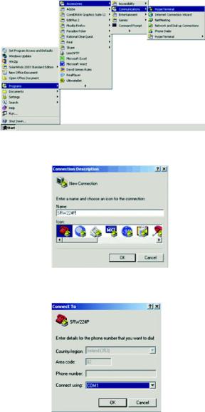
1.Click the Start button. Select Accessories and then select Communications. HyperTerminal should be one of the options listed in the next menu. Select HyperTerminal to run the utility program.
2.Enter a name for this connection. In the example shown, the name of connection is SRW224P. Select an icon for the application. Click OK.
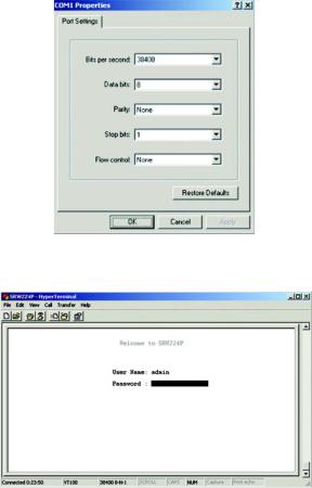
3.Select a port to communicate with the Switch. Select COM1 or COM2.
4.Set the serial port settings, as follows, then click OK. These settings should be:
•Bits per Second: 38400
•Databits: 8
•Parity: None
•Stop bits: 1
•Flow control: None
Chapter 4: Configuration using the Console Interface
Overview
Figure 4-1: Finding Hyperterminal
Figure 4-2: Connection Description
Figure 4-3: Password Screen
10
24-Port 10/100 + 2-Port Gigabit Switch with Webview and Power over Ethernet
Configuring the Switch through the Console Interface
Login
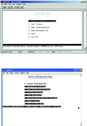
When you finish configuring HyperTerminal, the Login screen will appear. The first time you open the console interface, use the default username admin, and leave the password blank. You can set a new password later from the Password Setting screen.
Switch Screens
The console interface screens consist of a series of menus. Each menu has several options, which are listed vertically. A highlight in each menu lets you select the option you wish to choose; pressing the Enter key activates the highlighted option.
To navigate through the Console Interface use the Up Arrow or Down Arrow keys to move up or down, or use the number keys to select the respective option (for example, press the 5 key to highlight help) use the Enter key to select, and the Esc key to return to the previous selection; menu options and any values entered or present will get highlighted. The bottom of the window always has a listing of the appropriate key strokes.
Chapter 4: Configuration using the Console Interface
Configuring the Switch through the Console Interface
Figure 4-4: COM1 Properties
Figure 4-5: Login
11
24-Port 10/100 + 2-Port Gigabit Switch with Webview and Power over Ethernet
Switch Main Menu
The Main Menu screen displays six menu choices: System Configuration Menu, Port Status, Port Configuration, PoE Configuration, Help, and Logout.
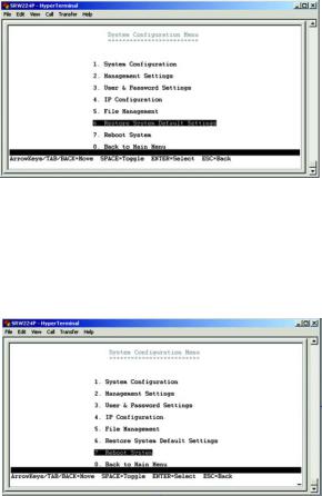
System Configuration Menu
System Configuration Menu displays:
1.System Configuration
2.Management Settings
3.User and Password Settings
4.IP Configuration
5.File Management
6.Restore System Default Setting
7.Reboot System
8.Back to Main Menu.
Chapter 4: Configuration using the Console Interface
Configuring the Switch through the Console Interface
Figure 4-6: Switch Main Menu
Figure 4-7: System Configuration Menu
12
24-Port 10/100 + 2-Port Gigabit Switch with Webview and Power over Ethernet
System Information
In System Information, you can check the Versions and General Information.
Versions
The version screen displays the Boot Version, Software Version, Loader Version and the Hardware Version.
Boot Version. This file runs when the Switch is turned on. It loads the operating system for the Switch.
Software Version. This file contains the programming code that runs the Switch.
Loader Version. This file loads the software from storage memory to main memory.
Hardware Version. The current hardware setup of the Switch.
General Information
The General Information screen displays the System Description, System Up Time, System Mac Address, System Contact, System Name and System Location
Chapter 4: Configuration using the Console Interface
Configuring the Switch through the Console Interface
Figure 4-8: System Information
Figure 4-9: Versions
Figure 4-10: General Information
13
24-Port 10/100 + 2-Port Gigabit Switch with Webview and Power over Ethernet
Management Settings
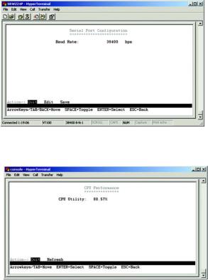
The Management Settings screen displays two menu choices: Serial Port Configuration and CPU Performance
Serial Port Configuration
The Serial Port Configuration screen displays the current setting for the baud rate. The baud rate can be changed by selecting edit then using the spacebar to toggle through the different baud rates. Use the save action to set the new baud rate.
Figure 4-11: Serial Port Configuration
CPU Performance
The CPU performance screen displays the percentage of processor power being used by the Switch.
Figure 4-12: CPU Performance
14
Chapter 4: Configuration using the Console Interface
Configuring the Switch through the Console Interface
24-Port 10/100 + 2-Port Gigabit Switch with Webview and Power over Ethernet
User and Password Settings
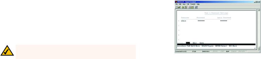
The User & Password Settings screen displays user account information on the Switch. The default account is the administrator account. To add a new user, use the arrow keys to select edit then enter the username of the new account and assign a password to the account. The password must be re-entered into the Again Password column to cofirm the password.
To save the new user account information, use the arrow key to select save and press enter.
NOTE: While only five accounts can be configured through the Switch’s console interface, up to 16 can be configured with the Switch’s web interface.
Chapter 4: Configuration using the Console Interface
Configuring the Switch through the Console Interface
Figure 4-13: User and Password Settings
15
24-Port 10/100 + 2-Port Gigabit Switch with Webview and Power over Ethernet
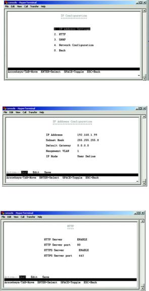
IP Configuration
The IP Configuration screen displays four menu choices: IP Address Settings, HTTP, SNMP and Network Configuration.
IP Address Settings
The IP Address Settings screen allows you to set the IP information for the Switch.
IP Address. This sets the Switch’s IP Address. The default setting is 192.168.1.254.
Subnet Mask. This combined with the IP Address defines the Switch’s network address.
Default Gateway. This defines the IP Address for the default gateway of the network.
Management VLAN. Set the ID number of the Management VLAN. This is the only VLAN through which you can gain management access to the Switch. By default, all ports on the Switch are members of VLAN 1, so a management station can be connected to any port on the Switch. However, if other VLANs are configured and you change the Management VLAN, you may lose management access to the Switch. In this case, you should reconnect the management station to a port that is a member of the Management VLAN.
IP Mode. Choose to have either a user defined IP address or to have it assigned by DHCP or BOOTP.
Figure 4-14: IP Configuration
Figure 4-15: IP Address Configuration Screen
HTTP
The HTTP screen allows you to set the Hyper Text Transfer Protocol information for the Switch.
HTTP Server. Enable or Disable the Switch’s HTTP server function.
HTTP Server port. Set the TCP port which HTTP packets are sent and received from.
HTTPS Server. Enable or Disable the Secure HTTP server function of the Switch.
HTTPS Server port. Set the TCP port witch HTTPS packets are sent and received from. |
Figure 4-16: HTTP |
16
Chapter 4: Configuration using the Console Interface
Configuring the Switch through the Console Interface
24-Port 10/100 + 2-Port Gigabit Switch with Webview and Power over Ethernet
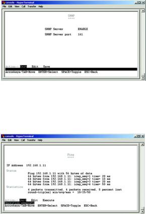
SNMP
The SNMP screen allows you to set the Switch’s SNMP settings.
SNMP Server. Enable or Disable the SNMP function for the Switch.
SNMP Port. Set the TCP port that will be used for sending and receiving SNMP packets.
Figure 4-17: SNMP
Network Configuration
The Network Configuration Screen allows you to use PING to test network connectivity. Enter the IP address of the interface or device you wish to PING and select the Execute action.
Figure 4-18: Network Configuration/PING
17
Chapter 4: Configuration using the Console Interface
Configuring the Switch through the Console Interface
24-Port 10/100 + 2-Port Gigabit Switch with Webview and Power over Ethernet
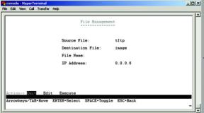
File Management
The File Management screen allows you to upload and download files to the Switch using TFTP.
Source File. Specify the location of the file to transfer. Select TFTP if the file is on a TFTP server, Image if the file is a local image file, or startup-config if the file is a local configuration file.
Destination File. Specify where the file is to be transferred. Select TFTP if the file is to be uploaded to a TFTP server, Image if the file is to be downloaded as a image file, startup-config if the file is a configuration file, or boot if the file is a boot file.
File Name. Enter the name of the file to be uploaded or downloaded.
IP Address. Enter the IP address of the TFTP server that will transfer the file.
Chapter 4: Configuration using the Console Interface
Configuring the Switch through the Console Interface
Figure 4-19: File Management
18
24-Port 10/100 + 2-Port Gigabit Switch with Webview and Power over Ethernet
Restore System Default Setting
To restore the Switch back to the factory default settings, select Restore System Default Setting and press Enter. A confirmation message will appear stating that All User Configuration data will be reset to Default. Continue? [y/ n]. Press the “y” key to continue or the “n” key to cancel the action.
Figure 4-20: Restore System Default Settings
Reboot System
If you would like to reboot the Switch, select Reboot System and press Enter.
Figure 4-21: Reboot System
19
Chapter 4: Configuration using the Console Interface
Configuring the Switch through the Console Interface
24-Port 10/100 + 2-Port Gigabit Switch with Webview and Power over Ethernet
Back to Main Menu
Select Back to Main Menu if you want to return to the main menu.
Figure 4-22: Back to Main Menu
20
Chapter 4: Configuration using the Console Interface
Configuring the Switch through the Console Interface
24-Port 10/100 + 2-Port Gigabit Switch with Webview and Power over Ethernet
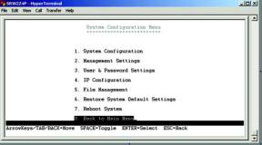
Port Status
This screen allows you to view the status of a port. The Port, Enable, Link Status, Spd/Dpx, and Flow Control are displayed.
Ports 1 through 24 are ethernet RJ-45 ports and ports 25 and 26 are Gigabit RJ-45 ports, Giga1 and Giga2. Each Gigabit port has a shared mini-Gbic port. If there is a connection to one of the mini-Gbic ports then the corresponding Gigabit RJ-45 port cannot be used.
Port Configuration
You can use the Port Configuration or screen to enable/disable an interface, set auto-negotiation and the interface capabilities to advertise, or manually fix the speed, duplex mode, and flow control.
Enable – Allows you to manually enable or disable an interface. You can disable an interface due to abnormal behavior (for example, excessive collisions), and then enable it again, once the problem has been resolved. You may also disable an interface for security reasons.
Auto-negotiation (Port Capabilities) – Allows auto-negotiation to be enabled/disabled. When auto-negotiation is enabled, you need to specify the capabilities to be advertised. When auto-negotiation is disabled, you can force the settings for speed, mode, and flow control.The following capabilities are supported.
•10half - Supports 10 Mbps half-duplex operation
•10full - Supports 10 Mbps full-duplex operation
•100half - Supports 100 Mbps half-duplex operation
•100full - Supports 100 Mbps full-duplex operation
•1000full (Gigabit only)- Supports 1000 Mbps full-duplex operation
(Default: Autonegotiation enabled; Advertised capabilities for 100BASE-TX – 10half, 10full, 100half, 100full; 1000BASE-T – 10half, 10full, 100half, 100full, 1000full; 1000BASE-SX/LX/LH (SFP) – 1000full; 100BASE-FX (SFP) – 100full
Speed/Duplex. Allows manual selection of port speed and duplex mode (that is, with auto-negotiation disabled).
Flow Control. Allows automatic or manual selection of flow control.
Chapter 4: Configuration using the Console Interface
Configuring the Switch through the Console Interface
Figure 4-23: Port Status
Figure 4-24: Port Configuration
21
24-Port 10/100 + 2-Port Gigabit Switch with Webview and Power over Ethernet
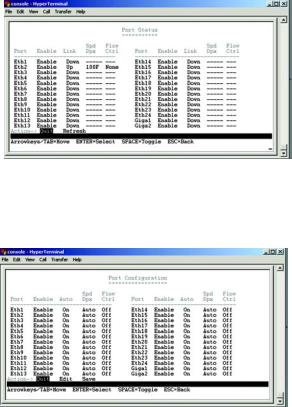
PoE Configuration
The PoE Main Menu screen displays three menu choices: System PoE Configuration, Port PoE Status and Port PoE Configuration.
System PoE Configuration
The Power Configuration screen allows you to set the PoE power allocation from the Switch to connected devices.
The Switch’s power management enables total Switch power and individual port power to be controlled within a configured power budget. Port power can be automatically turned on and off for connected devices, and a perport power priority can be set so that the Switch never exceeds its allocated power budget. When a device is connected to a port, its power requirements are detected by the Switch before power is supplied. If the power required by a device exceeds the power budget of the port or the whole Switch, power is not supplied.
Port PoE Status
The Power Port Status screen allows you to view the current PoE settings for each port on the Switch.
Ports can be set to one of three power priority levels, critical, high, or low. To control the power supply within the Switch’s budget, ports set at critical or high priority have power enabled in preference to those ports set at low priority. For example, when a device is connected to a port set to critical priority, the Switch supplies the required power, if necessary by dropping power to ports set for a lower priority. If power is dropped to some low-priority ports and later the power demands on the Switch fall back within its budget, the dropped power is automatically restored.
Chapter 4: Configuration using the Console Interface
Configuring the Switch through the Console Interface
Figure 4-25: PoE Main Menu
Figure 4-26: Power Configuration
Figure 4-27: Power Port Status
22
 Loading...