


 Loading...
USER GUIDE
BUSINESS SERIES
WebView Switches
Model: SRW2048, SRW2024, SRW2016, SRW248G4, SRW224G4
About This Guide
About This Guide
Icon Descriptions
While reading through the User Guide you may see various icons that call attention to specific items. Below is a description of these icons:
NOTE: This check mark indicates that there is a note of interest and is something that you should pay special attention to while using the product.
WARNING: This exclamation point indicates that there is a caution or warning and it is something that could damage your property or product.
WEB: This globe icon indicates a noteworthy website address or e-mail address.
Online Resources
Website addresses in this document are listed without http:// in front of the address because most current web browsers do not require it. If you use an older web browser, you may have to add http:// in front of the web address.
Resource |
Website |
|
|
Linksys |
www.linksys.com |
Linksys International |
www.linksys.com/international |
Glossary |
www.linksys.com/glossary |
Network Security |
www.linksys.com/security |
|
|
Copyright and Trademarks
Linksys is a registered trademark or trademark of Cisco Systems, Inc. and/ or its affiliates in the U.S. and certain other countries. Copyright © 2008 Cisco Systems, Inc. All rights reserved. Other brands and product names are trademarks or registered trademarks of their respective holders.
WebView Switches |
ii |

Table of Contents
Chapter 1: Introduction |
|
|
|
|
|
|
|
|
1 |
Chapter 2: Product Overview |
|
|
|
|
|
|
|
|
2 |
SRW2048 |
|
|
|
|
|
|
|
|
2 |
Front Panel |
|
|
|
|
|
|
|
|
2 |
LEDs . . . . . . . . . . . |
. . . . . . . . |
. . |
|
2 |
|||||
Back Panel . . . . . . . . |
. . |
. |
. . . . . . |
. |
|
. 2 |
|||
SRW2024 |
|
|
|
|
|
|
|
|
3 |
Front Panel |
|
|
|
|
|
|
|
|
3 |
LEDs . . . . . . . . . . . |
. . . . . . . . |
. . |
|
3 |
|||||
Back Panel . . . . . . . . |
. . |
. |
. . . . . . |
. |
|
. 3 |
|||
SRW2016 |
|
|
|
|
|
|
|
|
4 |
Front Panel |
|
|
|
|
|
|
|
|
4 |
LEDs . . . . . . . . . . . |
. . . . . . . . |
. . |
|
4 |
|||||
The Back Panel . . . . . . |
. . |
. |
. |
. |
. . . . |
. |
|
. 4 |
|
SRW248G4 |
|
|
|
|
|
|
|
|
5 |
Front Panel |
|
|
|
|
|
|
|
|
5 |
LEDs . . . . . . . . . . . |
. . . . . . . . |
. . |
|
5 |
|||||
Back Panel . . . . . . . . |
. . |
. |
. . . . . . |
. |
|
. 5 |
|||
SRW224G4 |
|
|
|
|
|
|
|
|
6 |
Front Panel |
|
|
|
|
|
|
|
|
6 |
LEDs . . . . . . . . . . . |
. . . . . . . . |
. . |
|
6 |
|||||
Back Panel . . . . . . . . |
. . |
. |
. . . . . . |
. |
|
. 6 |
|||
Chapter 3: Connecting the Switch |
|
|
|
|
|
|
|
8 |
|
Overview |
|
|
|
|
|
|
|
|
8 |
Placement Options . . . . . . |
. . |
. |
. |
. |
. . . . |
. |
|
. 8 |
|
Desktop Placement . . . . |
. . |
. |
. |
. |
. |
. . . |
. |
|
. 8 |
Rack-Mount Placement . . . . . . . . . . . . . . . . . . . . . . . . . . . . . . . . . . . . |
. . |
. |
8 |
||||||
Hardware Installation . . . . . . |
. |
. |
. . |
. |
|
. . . |
. |
. |
9 |
Configuring the Switch |
|
|
|
|
|
|
|
|
9 |
Chapter 4: Configuration Using the Console Interface |
|
10 |
|||||||
Overview |
|
|
|
|
|
|
|
|
10 |
Configuring the HyperTerminal Application |
|
|
|
|
|
10 |
|||
Connecting to the Switch through a Telnet Session |
|
|
10 |
||||||
Configuring the Switch through the Console Interface |
|
|
11 |
||||||
Switch Main Menu |
|
|
|
|
|
|
|
|
11 |
System Configuration Menu |
|
|
|
|
|
|
|
|
11 |
Port Status . . . . . . . . |
. . |
. |
. . . . . . |
. |
|
18 |
|||
Port Configuration . . . . . |
. |
. . |
. |
. |
. |
. . |
. . |
|
19 |
Help . . . . . . . . . . . |
. . . . . . . . |
. . |
|
19 |
|||||
WebView Switches |
i |

Table of Contents
Chapter 5: Advanced Configuration |
20 |
Overview
Accessing the Web-based Utility . . .
Setup > Summary . . . . . . . . .
Device Information . . . . . .
System Information . . . . . .
Setup > Network Settings . . . . . .
Identification . . . . . . . . .
IP Configuration . . . . . . . .
Setup > Time . . . . . . . . . . .
Set Time
Local Time . . . . . . . . . .
Daylight Saving SNTP Servers
Setup > Green Ethernet . . . . . .
Port Management > Port Settings . . Port Settings > Port Configuration
Port Management > Link Aggregation Link Aggregation > Detail . . . .
Port Management > LACP . . . . . .
VLAN Management > Create VLAN . . Single VLAN . . . . . . . . . .
VLAN Range . . . . . . . . . .
VLAN Table
VLAN Management > Port Setting VLAN Management > Ports to VLAN . VLAN Management > VLAN to Ports . VLAN Management > GVRP . . . . .
Statistics > RMON Statistics . . . . .
Statistics > RMON History . . . . . .
Log Table . . . . . . . . . . .
RMON History
Statistics > RMON Alarm . . . . . .
Statistics > RMON Events
Add Event . . . . . . . . . .
RMON Events Log . . . . . . .
Statistics > Port Utilization
Statistics > 802.1x Statistics . . . . .
Statistics > GVRP Statistics
ACL > IP Based ACL . . . . . . . .
ACL > MAC Based ACL . . . . . . .
Security > ACL Binding . . . . . . .
|
|
|
|
|
|
|
|
|
|
|
|
|
|
|
20 |
. |
. . |
|
. . |
. |
. |
. |
. 20 |
||||||||
. |
. . . |
|
. . |
|
. . 20 |
||||||||||
. . |
. . |
. . . |
. 20 |
||||||||||||
. . |
. . |
. . . |
. 21 |
||||||||||||
. . |
. . |
. . . |
.21 |
||||||||||||
. |
. . . |
|
. . |
|
. . 21 |
||||||||||
. . |
. . . |
. . |
.21 |
||||||||||||
. . |
. . |
|
. . |
|
. . 22 |
||||||||||
|
|
|
|
|
|
|
|
|
|
|
|
|
|
|
22 |
. . . |
. . |
. . |
. 22 |
||||||||||||
|
|
|
|
|
|
|
|
|
|
|
|
|
|
|
22 |
|
|
|
|
|
|
|
|
|
|
|
|
|
|
|
22 |
. . |
. . |
. . . |
. 23 |
||||||||||||
. . |
. . |
. . |
. . |
|
. . 23 |
||||||||||
|
|
|
|
|
|
|
|
|
|
|
|
|
|
|
24 |
. . |
. . |
. . |
. . |
|
. . |
|
. . 25 |
||||||||
. . |
. . |
. . |
. . 25 |
||||||||||||
. . |
. . |
. . . |
.26 |
||||||||||||
. |
. |
. |
. |
. . |
. |
. |
. |
|
. 26 |
||||||
. . . |
. . |
. . |
.26 |
||||||||||||
. . . |
. . |
. . |
.26 |
||||||||||||
|
|
|
|
|
|
|
|
|
|
|
|
|
|
|
26 |
|
|
|
|
|
|
|
|
|
|
|
|
|
|
|
27 |
. |
. . |
|
. . |
. |
. |
. |
. |
. |
. 27 |
||||||
. |
. . |
|
. . |
. |
. |
. |
. |
. |
. 28 |
||||||
. |
. . |
|
. . |
. . . 28 |
|||||||||||
. |
. . |
|
. . |
. . . 29 |
|||||||||||
. . |
. . |
. . . |
.30 |
||||||||||||
. . |
. . |
|
. . |
|
. . 30 |
||||||||||
|
|
|
|
|
|
|
|
|
|
|
|
|
|
|
30 |
. . |
. . |
. . . |
. 31 |
||||||||||||
|
|
|
|
|
|
|
|
|
|
|
|
|
|
|
32 |
. . . |
. . |
. . |
. |
32 |
|||||||||||
. |
. . |
|
. . . |
|
. . 32 |
||||||||||
|
|
|
|
|
|
|
|
|
|
|
|
|
|
|
32 |
. |
. . |
|
. . |
. . . 33 |
|||||||||||
|
|
|
|
|
|
|
|
|
|
|
|
|
|
|
33 |
. . |
. . . |
. . |
. 34 |
||||||||||||
. |
. . |
|
. . . |
|
. . 35 |
||||||||||
. |
. . |
|
. . . |
|
. . 36 |
||||||||||
WebView Switches |
ii |

Table of Contents
Security > RADIUS . . . . . . . . . . |
. |
. |
|
|
|
|
|
|
|
|
|
|
. . . . |
. |
36 |
||
Security > TACACS+ . . . . . . . . . |
. |
. |
. |
|
|
|
|
|
|
|
|
|
|
. . . |
. |
37 |
|
Security > 802.1x Settings . . . . . . |
. |
. |
. |
. . |
. |
. |
|
.37 |
|||||||||
802.1x Settings > Setting Timer |
|
|
|
|
|
|
|
|
|
|
|
|
|
|
|
|
38 |
Security > Port Security |
|
|
|
|
|
|
|
|
|
|
|
|
|
|
|
|
38 |
Security > Multiple Hosts |
|
|
|
|
|
|
|
|
|
|
|
|
|
|
|
|
39 |
Security > Storm Control |
|
|
|
|
|
|
|
|
|
|
|
|
|
|
|
|
40 |
QoS . . . . . . . . . . . . . |
. . . . . . . . . |
. |
40 |
||||||||||||||
QoS > CoS Settings . . . . . . . . . |
. |
. |
. |
. . . |
. |
40 |
|||||||||||
CoS Default . . . . . . . . . . |
. |
. |
. . . . . |
|
.41 |
||||||||||||
QoS > Queue Settings . . . . . . . . |
. |
. |
. |
. |
. . |
. |
41 |
||||||||||
QoS > DSCP Settings . . . . . . . . |
. |
. |
. |
. |
. . . |
|
.41 |
||||||||||
QoS > Bandwidth . . . . . . . . . . |
. |
. |
. . . . |
. |
41 |
||||||||||||
QoS > Basic Mode . . . . . . . . . . |
. |
. |
. . . . |
. |
42 |
||||||||||||
QoS > Advanced Mode |
|
|
|
|
|
|
|
|
|
|
|
|
|
|
|
|
42 |
Advanced Mode > Out of Profile DSCP . . . . . . . . . . |
. |
. 42 |
|||||||||||||||
Advanced Mode > Policy Name |
|
|
|
|
|
|
|
|
|
|
|
|
|
|
|
|
43 |
Advanced Mode > New Class Map |
|
|
|
|
|
|
|
|
|
|
|
|
|
|
|
|
43 |
Advanced Mode > New Aggregate Policer |
|
|
|
|
|
|
|
|
|
|
|
|
|
43 |
|||
Spanning Tree |
|
|
|
|
|
|
|
|
|
|
|
|
|
|
|
|
43 |
Spanning Tree > STP Status . . . . . . |
. |
. |
. |
. |
. |
. |
|
. |
44 |
||||||||
Spanning Tree > Global STP . . . . . . |
. |
. |
. |
. |
. |
. |
|
. |
44 |
||||||||
Global Setting |
|
|
|
|
|
|
|
|
|
|
|
|
|
|
|
|
44 |
Bridge Settings . . . . . . . . . |
. |
. |
. |
. . . |
. |
45 |
|||||||||||
Spanning Tree > STP Port Settings |
|
|
|
|
|
|
|
|
|
|
|
|
|
|
|
|
45 |
Spanning Tree > RSTP Port Settings . . |
. |
. |
. |
. . |
. |
|
. |
. |
|
. |
. |
46 |
|||||
Spanning Tree > MSTP Properties . . . |
. |
. |
. |
. . |
|
. . |
|
. |
. |
47 |
|||||||
Spanning Tree > MSTP Instance Settings |
|
|
|
|
|
|
|
|
|
|
|
|
|
|
|
|
48 |
Spanning Tree > MSTP Interface Settings . . . . . . . . . . |
. . 48 |
||||||||||||||||
Multicast > IGMP Snooping . . . . . . |
. |
. |
. |
. |
. |
. |
|
. |
49 |
||||||||
Multicast > Bridge Multicast |
|
|
|
|
|
|
|
|
|
|
|
|
|
|
|
|
50 |
Multicast > Bridge Multicast Forward All |
|
|
|
|
|
|
|
|
|
|
|
|
|
|
|
|
50 |
SNMP > Global Parameters . . . . . . |
. |
. |
. |
. |
. |
. |
|
. |
51 |
||||||||
SNMP > Views |
|
|
|
|
|
|
|
|
|
|
|
|
|
|
|
|
51 |
SNMP > Group Profile |
|
|
|
|
|
|
|
|
|
|
|
|
|
|
|
|
52 |
SNMP > Group Membership |
|
|
|
|
|
|
|
|
|
|
|
|
|
|
|
|
52 |
SNMP > Communities |
|
|
|
|
|
|
|
|
|
|
|
|
|
|
|
|
53 |
Base Table . . . . . . . . . . . |
. |
. . . . . |
. |
54 |
|||||||||||||
Advanced Table |
|
|
|
|
|
|
|
|
|
|
|
|
|
|
|
|
54 |
SNMP > Notification Filter . . . . . . |
. |
. |
. |
. . |
. |
. |
|
.54 |
|||||||||
SNMP > Notification Recipient . . . . |
. |
. |
. |
. . |
. |
|
. |
. |
55 |
||||||||
Admin > User Authentication |
|
|
|
|
|
|
|
|
|
|
|
|
|
|
|
|
55 |
Admin > Jumbo Frames . . . . . . . |
. |
. |
. |
. . |
. |
. |
56 |
||||||||||
WebView Switches |
iii |

Table of Contents
Admin > Static Address |
|
|
|
|
|
|
|
|
|
56 |
Query . . . . . . . . . . . |
. . |
. . . . . . . |
56 |
|||||||
Admin > Dynamic Address . . . . |
. |
. |
. |
. |
. |
. |
. |
. |
. |
57 |
Query . . . . . . . . . . . |
. |
|
|
. |
. . . . . . . |
57 |
||||
Admin > Logging . . . . . . . . |
. |
. |
. |
. |
. . . . . |
57 |
||||
Admin > Port Mirroring |
|
|
|
|
|
|
|
|
|
58 |
Admin > Cable Test . . . . . . . |
. |
. |
. |
. |
. |
. . . . |
58 |
|||
Admin > Save Configuration . . . |
. |
. |
. |
. |
. |
. . |
|
. . |
|
59 |
Via TFTP |
|
|
|
|
|
|
|
|
|
59 |
Via HTTP . . . . . . . . . . |
. |
. |
. . . . . . . |
59 |
||||||
Backup . . . . . . . . . . |
. |
. . |
. . . . . . |
.59 |
||||||
Admin > Firmware Upgrade |
|
|
|
|
|
|
|
|
|
59 |
Admin > Reboot . . . . . . . . |
. |
. |
. |
. |
. . . . . |
.60 |
||||
Admin > Factory Defaults . . . . |
. |
. |
. |
. |
. . |
. |
. |
. |
.60 |
|
Admin > Server Logs . . . . . . |
. |
. |
. |
. |
. . |
. . . |
.60 |
|||
Admin > Memory Logs . . . . . . |
. |
. |
. |
. |
. |
. |
. . . |
61 |
||
Admin > Flash Logs . . . . . . . |
. |
. |
. |
. |
. |
. . . . |
61 |
|||
Appendix A: About Gigabit Ethernet and Fiber Optic Cabling |
|
62 |
||||||||
Gigabit Ethernet . . . . . . . . |
. |
. |
. |
. |
. . . . . |
.62 |
||||
Fiber Optic Cabling . . . . . . . |
. |
. |
. |
. |
. |
. . . . |
62 |
|||
Appendix B: Windows Help |
|
|
|
|
|
|
|
|
|
63 |
TCP/IP |
|
|
|
|
|
|
|
|
|
63 |
Shared Resources . . . . . . . . |
. |
. |
. |
. |
. . . . . |
63 |
||||
Network Neighborhood/My Network Places . . . . . . . . . . . . |
63 |
|||||||||
Appendix C: Downloading using Xmodem |
|
|
|
|
|
64 |
||||
Startup Menu Procedures . . . . |
. |
. |
. |
. |
. . |
. |
. |
. |
.64 |
|
Appendix D: Glossary |
|
|
|
|
|
|
|
|
|
66 |
Appendix E: Specifications |
|
|
|
|
|
|
|
|
|
70 |
Appendix F: Warranty Information |
|
|
|
|
|
|
|
|
|
75 |
Limited Warranty |
|
|
|
|
|
|
|
|
|
75 |
Exclusions and Limitations |
|
|
|
|
|
|
|
|
|
75 |
Obtaining Warranty Service . . . . |
. |
. |
. |
. |
. |
. |
. |
. |
. |
75 |
Technical Support . . . . . . . . |
. |
. |
. |
. |
. . . . . |
76 |
||||
Appendix G: Regulatory Information |
|
|
|
|
|
|
|
77 |
||
FCC Statement . . . . . . . . . |
. |
. |
. |
. . . . . . |
77 |
|||||
Safety Notices |
|
|
|
|
|
|
|
|
|
77 |
Industry Canada Statement . . . . |
. |
. |
. |
. |
. |
. |
. |
. |
. |
77 |
Avis d’Industrie Canada |
|
|
|
|
|
|
|
|
|
77 |
WebView Switches |
iv |

Table of Contents
User Information for Consumer Products Covered by EU Directive 2002/96/EC on Waste
Electric and Electronic Equipment (WEEE) |
|
78 |
||
Appendix H: Software License Agreement |
82 |
|||
Software in Linksys Products: . . . . |
. |
. |
. . . . . . |
82 |
Software Licenses: . . . . . . . . . |
. |
. |
. . . . . |
. 82 |
Schedule 1 Linksys Software License Agreement |
82 |
|||
Schedule 2 . . . . . . . . . . |
. |
. . . . . . . |
83 |
|
Schedule 3 . . . . . . . . . . |
. |
. . . . . . . |
86 |
|
Appendix I: Contact Information |
|
|
|
89 |
WebView Switches |
v |

Chapter 1
Chapter 1:
Introduction
Thank you for choosing Linksys WebView Switches. This User Guide covers five product models:
•• SRW2048 48-port 10/100/1000 Gigabit Switch with WebView. Includes 48 10/100/1000 RJ-45 ports and 4 shared SFP (MiniGBIC) slots.
•• SRW2024 24-Port 10/100/1000 Gigabit Switch with WebView. Includes 24 10/100/1000 RJ-45 ports and 2 shared SFP (MiniGBIC) slots.
•• SRW2016 16-Port 10/100/1000 Gigabit Switch with WebView. Includes 16 10/100/1000 RJ-45 ports and 2 shared SFP (MiniGBIC) slots.
•• SRW248G4 48-port 10/100 + 4-Port Gigabit Switch with WebView. Includes 48 10/100 RJ-45 ports and 4 10/100/1000 RJ-45 ports and 2 shared SFP (MiniGBIC) slots.
•• SRW224G4 24-port 10/100 + 4-Port Gigabit Switch with WebView Includes 24 10/100 RJ-45 ports and 4 10/100/1000 RJ-45 ports and 2 shared SFP (MiniGBIC) slots.
For the purpose of this manual, whenever a feature applies to all models, the name WebView Switch will be referenced. If a specific model number is mentioned, then the feature is specific to that model.
The Linksys WebView Managed Switch allows you to expand your network securely. Configuration of the switch is secured using SSL for Web access. User control is secured using 802.1x security using a RADIUS authentication mechanism and can also be controlled using MAC-based filtering.
Extensive QoS features makes the solution ideal for realtime applications like Voice and Video. The 4 priority queues together with the Weighted Round Robin and Strict Priority scheduling techniques facilitate efficient coexistence of real-time traffic with data traffic allowing them each to meet their QoS needs.
Individual users or applications can be prioritized above others using various Class of Service options - by port, layer 2 priority (802.1p), and Layer 3 priority (TOS or DSCP). Intelligent Broadcast, and Multicast storm control minimizes and contain the effect of these types of traffic on regular traffic. IGMP Snooping limits bandwidth-intensive video traffic to only the requestors without flooding to all users.
Incoming traffic can be policed and outgoing traffic can be shaped allowing you to control network access and traffic flow.
Introduction
There are features that allow you to expand and grow your network of switches. Link aggregation allows multiple high-bandwidth trunks between switches to be setup.
This also provides a level of reliability in that the system continues to operate if one of the links break. Spanning Tree (STP), Fast Linkover, Rapid Spanning Tree (RSTP) and Multiple Spanning Tree (MSTP) allows you to build a mesh of switches increasing the availability of the system.
The rich management functionality of the WebView switches includes SNMP, RMON, Telnet, and HTTP Management options, allowing you to flexibly integrate and manage these devices in your network.
WebView Switches |
1 |
Chapter 2
Chapter 2:
Product Overview
SRW2048
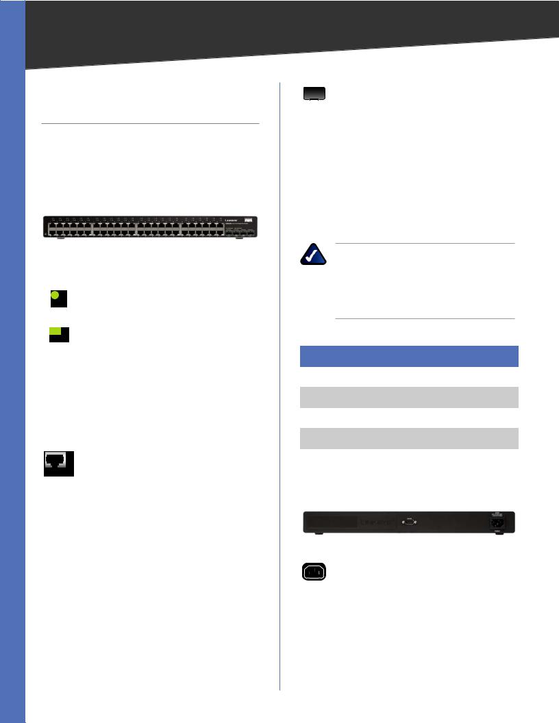
Front Panel
The Switch’s LEDs and ports are located on the front panel.
Front Panel of the SRW2048
LEDs
POWER (Green) Lights up green to indicate that power is being supplied to the Switch.
LINK/ACT (1-48) (Green/Amber) Lights up green to indicate a functional 10/100-Mbps network link through the corresponding port (1 through 48) with an attached device. It flashes to indicate that the Switch is actively sending or receiving data over that port. Lights up amber to indicate a 1000-Mbps connection on the corresponding port (1 through 48) with an attached device. It flashes to indicate that the Switch is actively sending or receiving data over that port.
ETHERNET 1-48 The Switch is equipped with 48 auto-sensing, Ethernet network ports, which use RJ-45 connectors. The Fast Ethernet ports support network speeds of 10 Mbps, 100 Mbps, or 1000 Mbps. They can operate in half and full-duplex modes. Auto-sensing technology enables each port to automatically detect the speed of the device connected to it (10 Mbps, 100 Mbps, or 1000 Mbps), and adjust its speed and duplex accordingly.
Product Overview
MiniGBIC (1-4) The miniGBIC (gigabit interface converter) port is a connection point for a miniGBIC expansion module, so the Switch can be uplinked via fiber to another switch. The MiniGBIC port provides a link to a high-speed network segment or individual workstation at speeds of up to 1000 Mbps.
Use the Linksys MGBT1, MGBSX1, or MGBLH1 miniGBIC modules with the Switch. The MGBSX1 and the MGBLH1 require fiber cabling with LC connectors, while the MGBT1 requires a Category 5e Ethernet cable with an RJ-45 connector.
NOTE: On the SRW2048, MiniGBIC ports are shared with standard ports. If a miniGBIC port is used, then the shared standard port on the Switch cannot be used. The following table provides port mapping details of the SRW2048 Switch.
SRW2048 Shared Port Mapping
miniGBIC Port |
Standard Port |
|
|
miniGBIC 1 |
Port 23 |
miniGBIC 2 |
Port 24 |
miniGBIC 3 |
Port 47 |
miniGBIC 4 |
Port 48 |
|
|
Back Panel
The power port is located on the back panel of the Switch.
Back Panel of the SRW2048
POWER The Power port is where you will connect the AC power.
WebView Switches |
2 |

Chapter 2 |
Product Overview |
CONSOLE The Switch is equipped with a serial port labeled Console (located on the back of the switch) that allows you to connect to a computer’s serial port (for configuration purposes) using the provided serial cable. You can use HyperTerminal to manage the Switch using the console port.
Refer to Chapter 4: Configuration Using the Console Interface for more information.
NOTE: If you need to reset the Switch, unplug the power cord from the back of the Switch. Wait a few seconds and then reconnect it.
SRW2024
Front Panel
The Switch’s LEDs and ports are located on the front panel.
Front Panel of the SRW2024
LEDs
POWER (Green) Lights up green to indicate that power is being supplied to the Switch.
LINK/ACT (1-24) (Green/Amber) Lights up green to indicate a functional 10/100-Mbps network link through the corresponding port (1 through 24) with an attached device. It flashes to indicate that the Switch is actively sending or receiving data over that port. Lights up amber to indicate a 1000-Mbps connection on the corresponding port (1 through 24) with an attached device. It flashes to indicate that the Switch is actively sending or receiving data over that port.
ETHERNET 1-24 The Switch is equipped with 24 auto-sensing Ethernet network ports, which use RJ-45 connectors. The Fast Ethernet ports support network speeds.The Fast Ethernet ports support network speeds of 10 Mbps, 100 Mbps, or 1000 Mbps. They can operate in half and full-duplex modes. Auto-sensing technology enables each port to automatically detect the speed of the device connected to it (10 Mbps, 100 Mbps, or 1000 Mbps), and adjust its speed and duplex accordingly.
MiniGBIC (1-2) The miniGBIC (gigabit interface converter) port is a connection point for a miniGBIC expansion module, so the Switch can be uplinked via fiber to another switch. The MiniGBIC port provides a link to a high-speed network segment or individual workstation at speeds of up to 1000 Mbps.
Use the Linksys MGBT1, MGBSX1, or MGBLH1 miniGBIC modules with the Switch. The MGBSX1 and the MGBLH1 require fiber cabling with LC connectors, while the MGBT1 requires a Category 5e Ethernet cable with an RJ-45 connector.
NOTE: On the SRW2024, MiniGBIC ports are shared with standard ports. If a miniGBIC port is used, then the shared standard port on the Switch cannot be used. The following table provides port mapping details of the SRW2024 Switch.
SRW2024 Shared Port Mapping
miniGBIC Port |
Standard Port |
|
|
miniGBIC 1 |
Port 12 |
miniGBIC 2 |
Port 24 |
|
|
Back Panel
The power port is located on the back panel of the Switch.
Back Panel of the SRW2024
POWER The Power port is where you will connect the AC power.
WebView Switches |
3 |
Chapter 2 |
Product Overview |
CONSOLE The Switch is equipped with a serial port labeled Console (located on the back of the switch) that allows you to connect to a computer’s serial port (for configuration purposes) using the provided serial cable. You can use HyperTerminal to manage the Switch using the console port.
Refer to Chapter 4: Configuration Using the Console Interface for more information.
NOTE: If you need to reset the Switch, unplug the power cord from the back of the Switch. Wait a few seconds and then reconnect it.
SRW2016
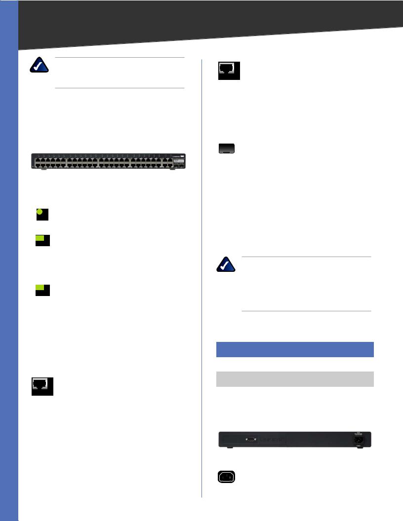
Front Panel
The Switch’s LEDs and ports are located on the front panel.
Front Panel of the SRW2016
LEDs
POWER (Green) Lights up green to indicate that power is being supplied to the Switch.
LINK/ACT (1-16) (Green) Lights up green to indicate a functional 10/100-Mbps network link through the corresponding port (1 through 16) with an attached device. It flashes to indicate that the Switch is actively sending or receiving data over that port.
Gigabit (1-16) (Amber) Lights up amber to indicate a 1000-Mbps connection on the corresponding port (1 through 16) with an attached device.
ETHERNET 1-16 The Switch is equipped with 16 auto-sensing, Ethernet network ports, which use RJ-45 connectors. The Fast Ethernet ports support network speeds of 10 Mbps, 100 Mbps, or 1000 Mbps. They can operate in half and full-duplex modes. Auto-sensing technology enables each port to automatically detect the speed of the device connected to it (10 Mbps, 100 Mbps, or 1000 Mbps), and adjust its speed and duplex accordingly.
MiniGBIC (1-2) The miniGBIC (gigabit interface converter) port is a connection point for a miniGBIC expansion module, so the Switch can be uplinked via fiber to another switch. The MiniGBIC port provides a link to a high-speed network segment or individual workstation at speeds of up to 1000 Mbps.
Use the Linksys MGBT1, MGBSX1, or MGBLH1 miniGBIC modules with the Switch. The MGBSX1 and the MGBLH1 require fiber cabling with LC connectors, while the MGBT1 requires a Category 5e Ethernet cable with an RJ-45 connector.
NOTE: On the SRW2016, MiniGBIC ports are shared with standard ports. If a miniGBIC port is used, then the shared standard port on the Switch cannot be used. The following table provides port mapping details of the SRW2016 Switch.
SRW2016 Shared Port Mapping
miniGBIC Port |
Standard Port |
|
|
miniGBIC 1 |
Port 8 |
miniGBIC 2 |
Port 16 |
|
|
The Back Panel
The power port is located on the back panel of the Switch.
Back Panel of the SRW2016
POWER The Power port is where you will connect the AC power.
CONSOLE The Switch is equipped with a serial port labeled Console (located on the back of the switch) that allows you to connect to a computer’s serial port (for configuration purposes) using the provided serial cable. You can use HyperTerminal to manage the Switch using the console port.
Refer to Chapter 4: Configuration Using the Console Interface for more information.
WebView Switches |
4 |
Chapter 2 |
Product Overview |
NOTE: If you need to reset the Switch, unplug the power cord from the back of the Switch. Wait a few seconds and then reconnect it.
SRW248G4
Front Panel
The Switch’s LEDs and ports are located on the front panel.
Front Panel of the SRW248G4
LEDs
POWER (Green) Lights up green to indicate that power is being supplied to the Switch.
LINK/ACT (1-48) (Green) Lights up green to indicate a functional 10/100-Mbps network link through the corresponding port (1 through 48) with an attached device. It flashes to indicate that the Switch is actively sending or receiving data over that port.
LINK/ACT (G1-G4) (Green/Amber) Lights up green to indicate a functional 10/100Mbps network link through the corresponding port (G1 through G4) with an attached device. It flashes to indicate that the Switch is actively sending or receiving data over that port.
Lights up orange to indicate a 1000-Mbps connection on the corresponding port (G1 through G4) with an attached device. It flashes to indicate that the Switch is actively sending or receiving data over that port.
ETHERNET 1-48 The Switch is equipped with 48 auto-sensing Ethernet network ports, which use RJ-45 connectors. The Fast Ethernet ports support network speeds of 10 Mbps or 100 Mbps. They can operate in half and full-duplex modes. Auto-sensing technology enables each port to automatically detect the speed of the device connected to it (10 Mbps or 100 Mbps), and adjust its speed and duplex accordingly.
ETHERNET G1-G4 The Switch is equipped with 4 auto-sensing Gigabit Ethernet network ports, whichuseRJ-45connectors.TheGigabitEthernet ports support network speeds of 10 Mbps, 100 Mbps, or 1000 Mbps. They can operate in half and full-duplex modes. Auto-sensing technology enables each port to automatically detect the speed of the device connected to it (10 Mbps, 100 Mbps, or 1000 Mbps), and adjust its speed and duplex accordingly.
MiniGBIC (1-2) The miniGBIC (gigabit interface converter) port is a connection point for a miniGBIC expansion module, so the Switch can be uplinked via fiber to another switch. The MiniGBIC port provides a link to a high-speed network segment or individual workstation at speeds of up to 1000 Mbps.
Use the Linksys MGBT1, MGBSX1, or MGBLH1 miniGBIC modules with the Switch. The MGBSX1 and the MGBLH1 require fiber cabling with LC connectors, while the MGBT1 requires a Category 5e Ethernet cable with an RJ-45 connector.
NOTE: On the SRW248G4, MiniGBIC ports are shared with Gigabit Ethernet ports. If a miniGBIC port is used, then the shared Gigabit Ethernet port on the Switch cannot be used. The following table provides port mapping details of the SRW248G4 Switch.
SRW248G4 Shared Port Mapping
miniGBIC Port |
Standard Port |
|
|
miniGBIC 1 |
Port G3 |
miniGBIC 2 |
Port G4 |
|
|
Back Panel
The power port is located on the back panel of the Switch.
Back Panel of the SRW248G4
POWER The Power port is where you will connect the AC power.
WebView Switches |
5 |

Chapter 2 |
Product Overview |
CONSOLE The Switch is equipped with a serial port labeled Console (located on the back of the switch) that allows you to connect to a computer’s serial port (for configuration purposes) using the provided serial cable. You can use HyperTerminal to manage the Switch using the console port.
Refer to Chapter 4: Configuration Using the Console Interface for more information.
NOTE: If you need to reset the Switch, unplug the power cord from the back of the Switch. Wait a few seconds and then reconnect it.
SRW224G4
Front Panel
The Switch’s LEDs and ports are located on the front panel.
Front Panel of the SRW224G4
LEDs
POWER (Green) Lights up green to indicate that power is being supplied to the Switch.
LINK/ACT (1-24) (Green) Lights up green to indicate a functional 10/100-Mbps network link through the corresponding port (1 through 24) with an attached device. It flashes to indicate that the Switch is actively sending or receiving data over that port.
LINK/ACT (G1-G4) (Green) Lights up green to indicate a functional 10/100-Mbps network link through the corresponding port (G1 through G4) with an attached device. It flashes to indicate that the Switch is actively sending or receiving data over that port..
1000Mbps (G1-G4) (Amber) Lights up amber to indicate a 1000-Mbps connection on the corresponding port (G1 through G4) with an attached device.
ETHERNET 1-24 The Switch is equipped with 24 auto-sensing, Ethernet network ports, which use RJ-45 connectors. The Fast Ethernet ports support network speeds of 10 Mbps, 100 Mbps, or 1000 Mbps. They can operate in half and full-duplex modes. Auto-sensing technology enables each port to automatically detect the speed of the device connected to it (10 Mbps, 100 Mbps, or 1000 Mbps), and adjust its speed and duplex accordingly.
ETHERNET G1-G4 The Switch is equipped with 4 auto-sensing Gigabit Ethernet network ports, which use RJ-45 connectors. The Gigabit Ethernet ports support network speeds of 10 Mbps, 100 Mbps, or 1000 Mbps. They can operate in half and full-duplex modes. Autosensing technology enables each port to automatically detect the speed of the device connected to it (10 Mbps, 100 Mbps, or 1000 Mbps), and adjust its speed and duplex accordingly.
MiniGBIC (1-2) The miniGBIC (gigabit interface converter) port is a connection point for a miniGBIC expansion module, so the Switch can be uplinked via fiber to another switch. The MiniGBIC port provides a link to a high-speed network segment or individual workstation at speeds of up to 1000 Mbps.
Use the Linksys MGBT1, MGBSX1, or MGBLH1 miniGBIC modules with the Switch. The MGBSX1 and the MGBLH1 require fiber cabling with LC connectors, while the MGBT1 requires a Category 5e Ethernet cable with an RJ-45 connector.
SRW224G4 Shared Port Mapping
miniGBIC Port |
Standard Port |
|
|
miniGBIC 1 |
Port G3 |
miniGBIC 2 |
Port G4 |
|
|
Back Panel
The power port is located on the back panel of the Switch.
Back Panel of the SRW224G4
WebView Switches |
6 |

Chapter 2 |
Product Overview |
POWER The Power port is where you will connect the AC power.
CONSOLE The Switch is equipped with a serial port labeled Console (located on the back of the switch) that allows you to connect to a computer’s serial port (for configuration purposes) using the provided serial cable. You can use HyperTerminal to manage the Switch using the console port.
Refer to Chapter 4: Configuration Using the Console Interface for more information.
NOTE: If you need to reset the Switch, unplug the power cord from the back of the Switch. Wait a few seconds and then reconnect it.
WebView Switches |
7 |
Chapter 3
Chapter 3:
Connecting the Switch
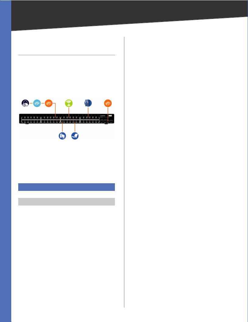
Overview
This chapter will explain how to connect network devices to the Switch. For an example of a typical network configuration, see the application diagram shown below.
|
Cable/DSL |
|
|
|
Uplink via Fiber |
Internet |
Modem |
Router |
Wireless Access Point |
Server |
to Switch |
10/100/1000 10/100 Desktop Notebook
Typical Network Configuration for the SRW2048
When you connect your network devices, make sure you don’t exceed the maximum cabling distances, which are listed in the following table:
Maximum Cabling Distances
From |
To |
Maximum Distance |
|
|
|
Switch |
Switch or Hub |
100 meters (328 feet) |
Hub |
Hub |
5 meters (16.4 feet) |
Switch or Hub |
Computer |
100 meters (328 feet) |
|
|
|
††A hub refers to any type of 100-Mbps hub, including regular hubs and stackable hubs. A 10-Mbps hub connected to another 10-Mbps hub can span up to 100 meters (328 feet).
Before You Install the Switch...
When you choose a location for the Switch, observe the following guidelines:
•• Make sure the Switch is accessible and that the cables can be easily connected.
•• Keep cabling away from sources of electrical noise, power lines, and fluorescent lighting fixtures.
•• Position the Switch away from water and moisture sources.
•• To ensure adequate air flow around the Switch, provide a minimum clearance of two inches (50 mm).
•• Do not stack free-standing Switches more than four units high.
Connecting the Switch
Placement Options
There are two ways to physically install the Switch, either set the Switch on its four rubber feet for desktop placement or mount the switch in a standard-sized, 482.6-mm wide, 1U-high rack for rack-mount placement.
Desktop Placement
•• Attach the rubber feet to the recessed areas on the bottom of the Switch.
•• Place the Switch on a desktop near an AC power source.
•• Keep enough ventilation space for the switch and check the environmental restrictions mentioned in the Specifications Appendix as you are placing the Switch.
•• Connect the Switch to network devices according to the Hardware Installation instructions below.
Rack-Mount Placement
When rack-mounting the Switch, please observe the following guidelines
•• Elevated Operating Ambient If installed in a closed or multi-unit rack assembly, the operating ambient temperature of the rack environment may be greater than the room ambient temperature. Therefore, consideration should be given to installing the equipment in an environment compatible with the maximum ambient temperature (Tma) specified by the manufacturer.
•• Reduced Air Flow Installation of the equipment in a rack should be such that the amount of air flow required for safe operation of the equipment is not compromised.
•• Mechanical Loading Mounting of the equipment in the rack should be such that a hazardous condition is not achieved due to uneven mechanical loading.
•• Circuit Overloading Consideration should be given to the connection of the equipment to the supply circuit and the effect that overloading of the circuits might have on overcurrent protection and supply wiring. Appropriate consideration of equipment nameplate ratings should be used when addressing this concern.
•• Reliable Earthing Reliable earthing of rack-mounted equipment should be maintained. Particular attention should be given to supply connections other than direct connections to the branch circuit (for example, use of power strips).
WebView Switches |
8 |
Chapter 3 |
Connecting the Switch |
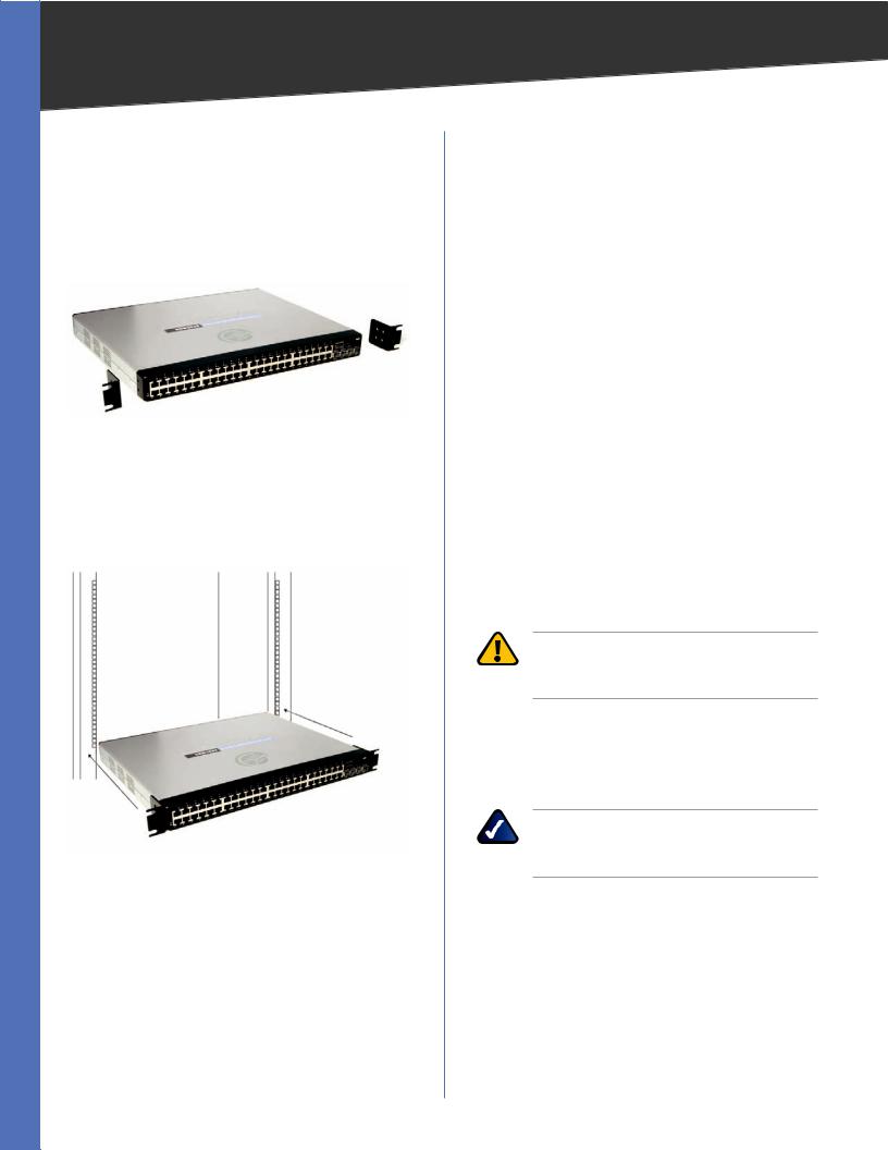
To rack-mount the Switch in any standard 482.6-mm wide, 1U high rack, follow the instructions described below.
1.Place the Switch on a hard flat surface with the front panel facing you.
2.Attach a rack–mount bracket to one side of the Switch with the supplied screws and secure the bracket tightly.
Attach the Brackets to the Switch
3.Follow the same steps to attach the other bracket to the opposite side.
4.After the brackets are attached to the Switch, use suitable screws to securely attach the brackets to any standard 482.6-mm rack.
Mount the Switch in the Rack
5.Connect the Switch to network devices according to the Hardware Installation instructions below.
Hardware Installation
To connect network devices to the Switch, follow these instructions:
1.Make sure all the devices you will connect to the Switch are powered off.
2.For 10/100-Mbps devices, connect a Category 5 Ethernet network cable to one of the numbered ports on the Switch. For a 1000-Mbps device, connect a Category 5e Ethernet network cable to one of the numbered ports on the Switch.
3.Connect the other end to a PC or other network device.
4.Repeat steps 2 and 3 to connect additional devices.
5.If you are using the miniGBIC port, then connect the miniGBIC module to the miniGBIC port. For detailed instructions, refer to the module’s documentation.
6.If you will use the Switch’s console interface to configure the Switch, then connect the supplied serial cable to the Switch’s Console port, and tighten the captive retaining screws. Connect the other end to your PC’s serial port. (This PC must be running the VT100 terminal emulation software, such as HyperTerminal.)
7.Connect the supplied power cord to the Switch’s power port, and plug the other end into an electrical outlet.
WARNING: Make sure you use the power cord that is supplied with the Switch. Use of a different power cord could damage the Switch.
8.Power on the network devices connected to the Switch. Each active port’s corresponding Link/Act LED will light up on the Switch. If a port has an active Gigabit connection, then its corresponding Gigabit LED will also light up.
NOTE: If you need to reset the Switch, unplug the power cord from the back of the Switch. Wait a few seconds and then reconnect it.
Configuring the Switch
To use the Switch’s console interface to configure the Switch, proceed to Chapter 4: Configuration Using the Console Interface for directions.
To use the Switch’s Web-based Utility to configure the Switch, proceed to Chapter 5: Advanced Configuration.
WebView Switches |
9 |
Chapter 4
Chapter 4:
Configuration Using the
Console Interface
Overview
The Switch features a menu-driven console interface for basic configuration of the Switch and management of your network. The Switch can be configured using CLI through the console interface or through a Telnet connection. This chapter describes console interface configuration. Configuration can also be performed through the web utility, which is covered in the next chapter.
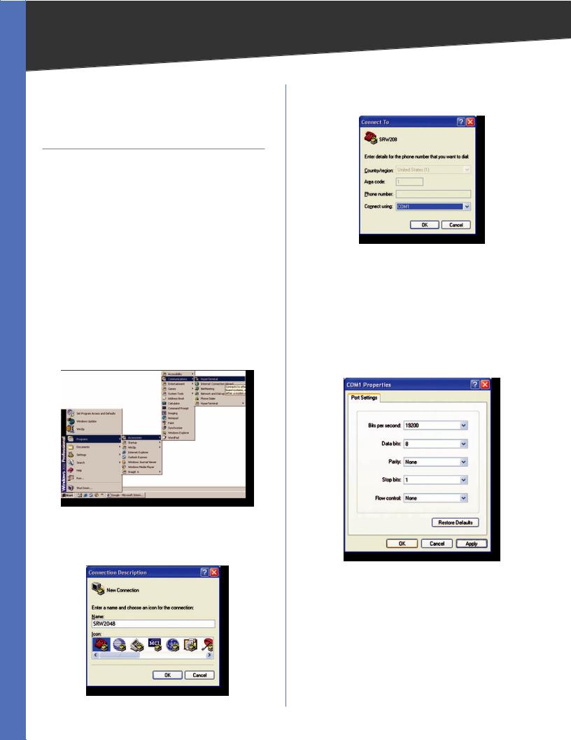
Configuring the HyperTerminal Application
Before using the console interface, configure the HyperTerminal application on your PC as follows:
1.Click the Start button.
2.Select Programs > Accessories > Communications > HyperTerminal.
Start > Programs > Accessories > Communications > HyperTerminal
3.Enter a name for this connection. In this example, the name of connection is SRW2048. Select an icon for the application, then click OK.
HyperTerminal Connection Description Screen
WebView Switches
Configuration Using the Console Interface
4.Select a port to communicate with the Switch: COM1,
COM2, or TCP/IP.
HyperTerminal Connect To Screen
5.Set the serial port settings as follows: Bits per second: 38,400
Data bits: 8 Parity: None Stop bits: 1
Flow control: None
6.Click OK.
HyperTerminal Properties Screen
Connecting to the Switch through a Telnet Session
Open a command-line editor and enter telnet 192.168.1.254. Then, press the Enter key.
The Login screen appears. The first time you open the command-line interface (CLI), select Edit and press Enter. Enter admin in the User Name field. Leave the Password field blank.
10
Chapter 4 |
Configuration Using the Console Interface |
Telnet Login Screen
Press the Esc button to return to the login screen. Use the right arrow button to navigate to the Execute option and press the Enter button to open CLI interface.
Configuring the Switch through the Console Interface
The console screens consist of a series of menus. Each menu has several options, which are listed vertically. You select a menu option when you highlight it; pressing the Enter key activates the highlighted option.
To navigate through the menus and actions of the console interface, use the up or down arrow keys to move up or down, and use the left or right arrow keys to move left or right. Use the Enter key to select a menu option, and use the Esc key to return to the previous selection. Menu options and any values entered or present will be highlighted. The bottom of the screen lists the actions available.
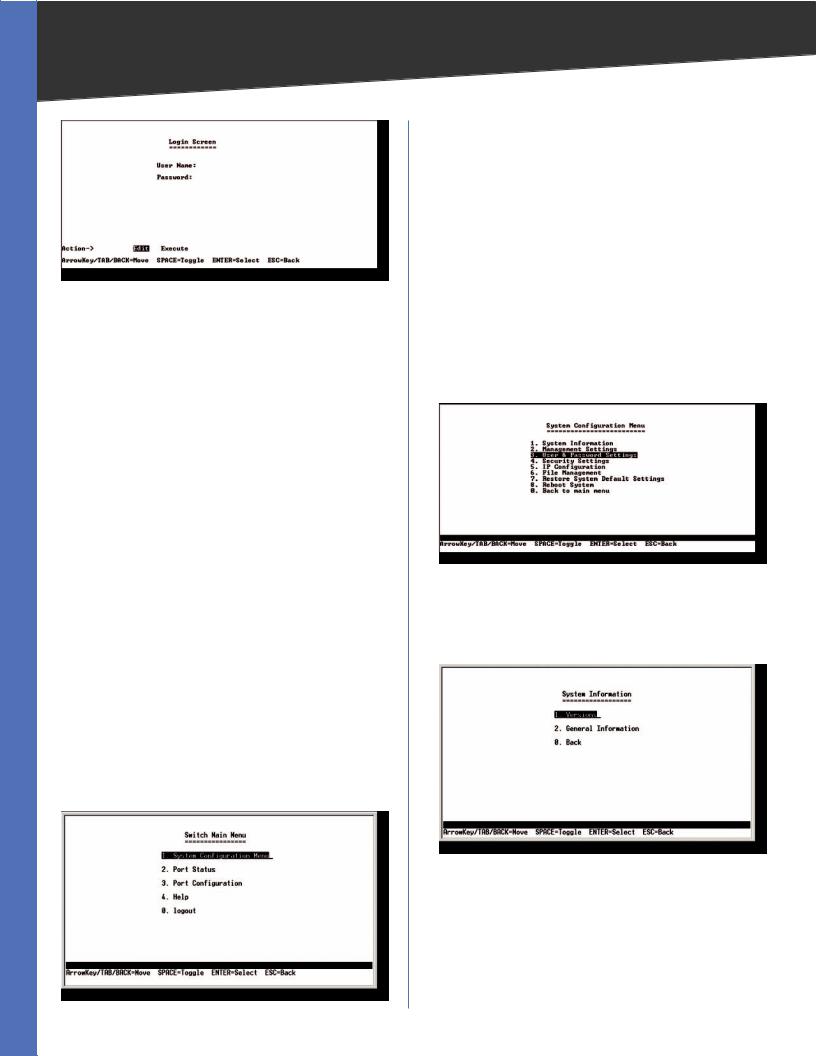
Switch Main Menu
The System Main Menu screen displays these choices:
1.System Configuration Information Menu
2.Port Status
3.Port Configuration
4.Help
5.Logout
Switch Main Menu
WebView Switches
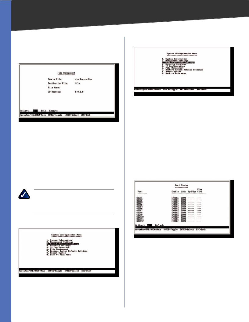
System Configuration Menu
On the System Configuration Menu screen, you can choose from the following:
1.System Information
2.Management Settings
3.User & Password Settings
4.Security Settings
5.IP Configuration
6.File Management
7.Restore System Default Settings
8.Reboot System
9.Back to main menu
System Configuration Menu
System Information
UsingSystemInformationscreen,youcanchecktheSwitch’s firmware versions and general system information.
System Configuration Menu
11
Chapter 4 |
Configuration Using the Console Interface |
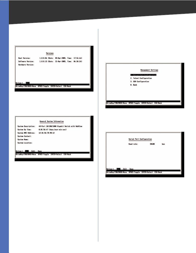
Versions
The Versions screen displays the Switch’s boot, software, and hardware firmware versions.
Versions
General System Information
The General System Information screen displays general information about the Switch.
General System Information
Select Edit and press the Enter key to make changes. When your changes are complete, press the Esc key to return to the Action menu. Select Save and press the Enter key to save your changes. To exit, select Quit and press the Enter key.
Management Settings
From the Management Settings screen, you can set the following options:
•• Serial Port Session Configuration
•• Telnet Session Configuration
•• Secure Telnet (SSH) Configuration.
Management Settings Menu
Serial Port Configuration
The Serial Port Configuration screen displays the Switch’s baud rate.
Serial Port Configuration
Select Edit and press the Enter key to make changes. Toggle to the desired speed and when your changes are complete, press the Esc key to return to the Action menu. Select Save and press the Enter key to save your changes. To exit, select Quit and press the Enter key.
WebView Switches |
12 |
Chapter 4 |
Configuration Using the Console Interface |
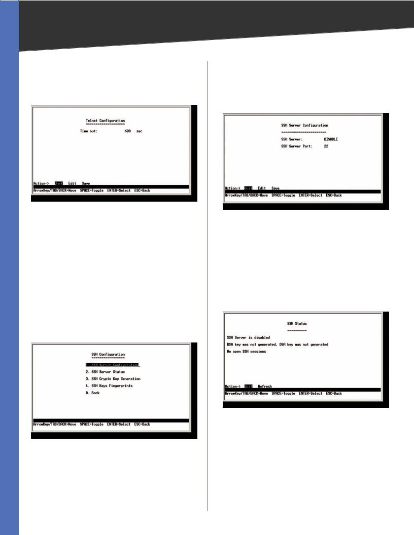
Telnet Configuration
The Telnet Configuration screen displays the timeout value. The value is entered in seconds. If you do not want the Telnet session to timeout, you may enter a value of 0 sec.
Telnet Configuration
Select Edit and press the Enter key to make changes. When your changes are complete, press the Esc key to return to the Action menu. Select Save and press the Enter key to save your changes. To exit, select Quit and press the Enter key.
SSH Configuration
The SSH Configuration screen displays the following options:
•• SSH Server Configuration
•• SSH Server Status
•• SSH Crypto Key Generation
•• SSH Keys Fingerprints
SSH Configuration
SSH Server Configuration
On the SSH Server Configuration screen, you can enable or disable the SSH Server by navigating to the SSH Server option and using the SPACE bar to toggle the option. The SSH Server Port can be modified by entering in the value.
SSH Server Configuration
Select Edit and press the Enter key to make changes. When your changes are complete, press the Esc key to return to the Action menu. Select Save and press the Enter key to save your changes. To exit, select Quit and press the Enter key.
SSH Status
The SSH Status screen displays whether the SSH Server is enabled, the RSA and DSA key status, and any open SSH sessions.
SSH Status
Select Refresh to update the screen if necessary. To exit, select Quit and press the Enter key.
WebView Switches |
13 |
Chapter 4 |
Configuration Using the Console Interface |
SSH Crypto Key Generation
On the SSH Crypto Key Generation screen, you can toggle between RSA and DSA using the SPACE bar. The SSH Public Key Length cannot be modified.
SSH Crypto Key Generation
Select Edit and press the Enter key to make changes. When your changes are complete, press the Esc key to return to the Action menu. Select Save and press the Enter key to save your changes. To exit, select Quit and press the Enter key.
SSH Keys Fingerprints
On the SSH Keys Fingerprints screen, the RSA and DSA keys are displayed if they have been generated.
Keys Fingerprints
Select Refresh to update the screen if necessary. To exit, select Quit and press the Enter key.
Username & Password Settings
From the Username & Password Settings screen, you can administer the user names and passwords of those accessing the Switch.
Username & Password Settings
Select Edit and press the Enter key to make changes. When your changes are complete, press the Esc key to return to the Action menu. Select Save and press the Enter key to save your changes. To exit, select Quit and press the Enter key.
NOTE: The Username & Password Settings screen can also be used to set passwords for other users.
Security Settings
The Security Settings screen enables you to configure security settings on the Switch, as well as generate and display the certificate.
Security Settings
WebView Switches |
14 |

Chapter 4 |
Configuration Using the Console Interface |
SSL Certificate Generation
Use the Certificate Generation screen to specify a devicegenerated certificate.
SSL Certificate Generation
Public Key Length Specifies the SSL RSA key length. (Range: 512–2048)
Organization Name Specifies the organization name. (Range: 1–64)
Locality or City Name Specifies the location or city name. (Range: 1–64)
State or Province Name Specifies the state or province name. (Range: 1–64)
Country Name Specifies the country name. (Range: 2–2)
Validity Term Specifies number of days certification is valid. (Range: 30–3650)
Show Certificate
Use the Show Certificate screen to display the internal certificate.
SSL Certificate
Disable Active Management Profile
To disable the active management profile, selecting
Disable Active Management Profile from the Security Settings screen. You are prompted for confirmation.
Security Settings
NOTE: This setting has no effect when Management Access Rules are not defined.
IP Configuration
The IPConfiguration screen lets you configure the following options:
•• IP Address Settings
•• HTTP Configuration
•• HTTPS Configuration
•• Network Configuration.
IP Configuration
WebView Switches |
15 |
Chapter 4 |
Configuration Using the Console Interface |
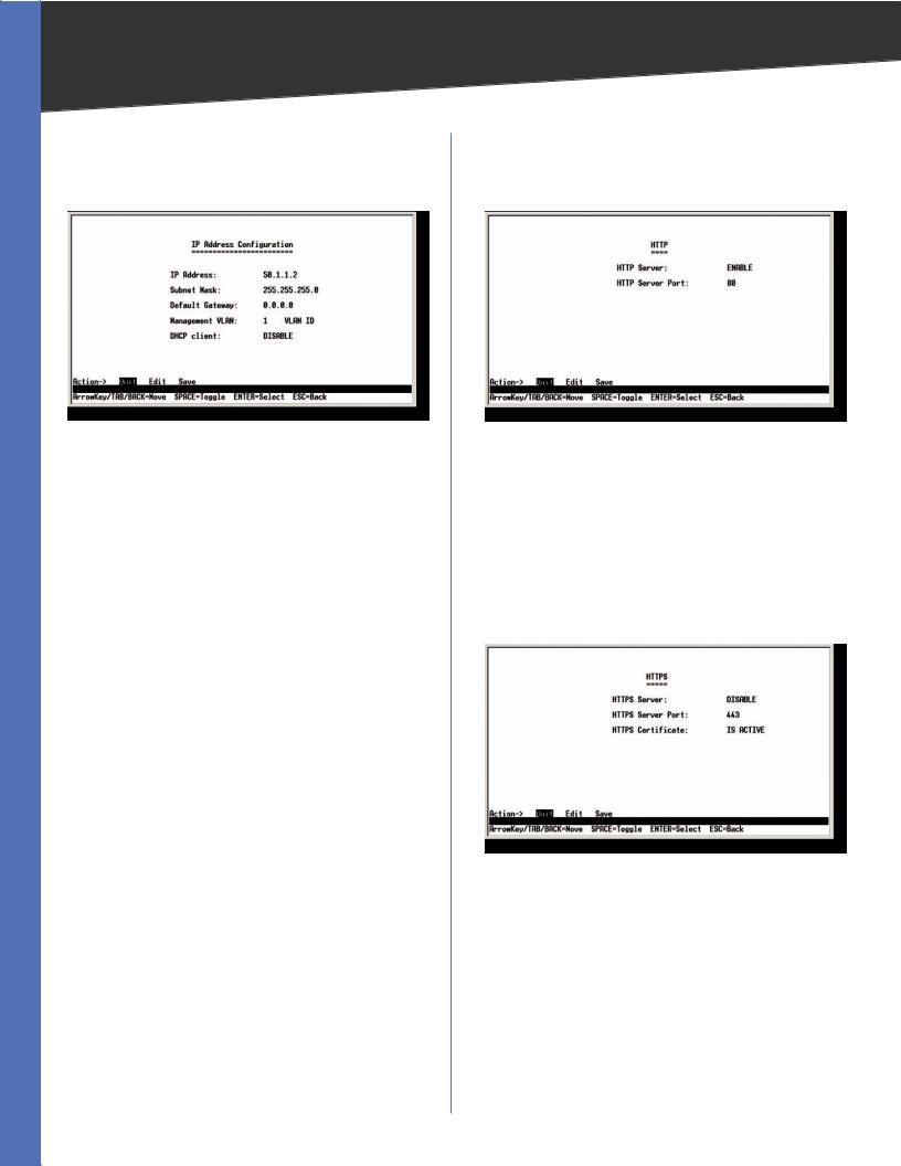
IP Address Configuration
The IP Address Configuration screen lets you configure the Switch’s IP address information.
IP Address Configuration
IP Address The IP Address of the Switch is displayed. (The default IP address is 192.168.1.254.) Verify that the address you enter is correct and does not conflict with another device on the network.
Subnet Mask The subnet mask of the Switch is displayed.
Default Gateway The IP address of your network’s default gateway is displayed.
Management VLAN The VLAN ID number is displayed.
DHCP client The status of the DHCP client is displayed. If you want the Switch to be a DHCP client, then select ENABLE. If you want to assign an static IP address to the Switch, then enter the IP settings and select DISABLE.
Select Edit to make changes. When your changes are complete, press the Esc key to return to the Action menu, and select Save to save your changes.
HTTP
The HTTP screen lets you configure the status and port number of the HTTP Server.
HTTP
Select Edit and press the Enter key to make changes. When your changes are complete, press the Esc key to return to the Action menu. Select Save and press the Enter key to save your changes. To exit, select Quit and press the Enter key.
HTTPS Configuration
The HTTPS Configuration screen lets you configure the HTTPS settings.You can enable or disable the HTTPS server and configure the port on which the session is enabled.
HTTPS Configuration
Select Edit and press the Enter key to make changes. When your changes are complete, press the Esc key to return to the Action menu. Select Save and press the Enter key to save your changes. To exit, select Quit and press the Enter key.
WebView Switches |
16 |
Chapter 4 |
Configuration Using the Console Interface |
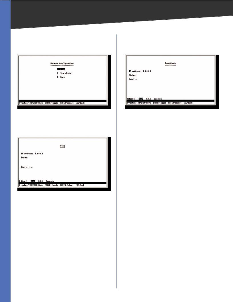
Network Configuration
The Network Configuration screen offers a choice of two tests: Ping and TraceRoute.
Network Configuration
Ping
The Ping screen displays the IP address of the location you want to contact.
Ping Test
Select Edit to change the IP address, and select Execute to begin the ping test.
After the ping test is complete, the Ping screen displays the IP address, status, and statistics of the ping test.
Select Edit and press the Enter key to make changes. When your changes are complete, press the Esc key to return to the Action menu. Select Save and press the Enter key to save your changes. To exit, select Quit and press the Enter key.
TraceRoute
The TraceRoute screen displays the IP address of the address whose route you want to trace.
TraceRoute Test
Select Edit to change the IP address, and select Execute to begin the traceroute test.
After the traceroute test is complete, the TraceRoute screen displays the IP address, status, and statistics of the traceroute test.
Select Edit and press the Enter key to make changes. When your changes are complete, press the Esc key to return to the Action menu. Select Save and press the Enter key to save your changes. To exit, select Quit and press the Enter key.
WebView Switches |
17 |
Chapter 4 |
Configuration Using the Console Interface |
File Management
The File Management screen allows you to upload or download files, such as the startup configuration, boot, or image file, using a TFTP server.
File Management
Select Edit to change the settings. When your changes are complete, press the Esc key to return to the Action menu, and select Execute to upload or download the designated file.
If you are downloading a new boot & image, please follow these steps:
1.Download the new boot code. DO NOT RESET THE DEVICE!
2.Download the new software image.
3.Reset the device now.
NOTE: When downloading a configuration file, be sure that it is a valid configuration file. If you have edited the file, ensure that only valid entries have been configured.
Restore System Default Settings
Restore System Default Settings
To restore the Switch back to the factory default settings, select Restore System Default Settings and press the
Enter key. You will be asked if you want to continue. Press the y key to restore the Switch’s default settings, or press the n key to cancel.
Reboot System
Reboot System
Select Reboot System and press the Enter key if you want to restart the Switch. You will be asked if you want to continue. Press the y key to reboot the Switch, or press the n key to cancel. After the Switch has rebooted, the Switch Main Menu screen will appear.
Back to main menu
Select Back to main menu and press the Enter key if you want to return to the Switch Main Menu screen.
Port Status
On the Switch Main Menu screen, select Port Status and press the Enter key if you want to view the status information for the Switch’s ports.
Port Status
The Port Status screen displays the port numbers, their status, Link status, speed and duplex mode, and status of flow control, which is the flow of packet transmissions.
If you want to change any settings for a port, you must use the Port Configuration screen.
WebView Switches |
18 |
Chapter 4 |
Configuration Using the Console Interface |
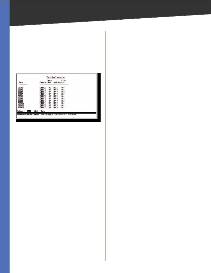
Port Configuration
OntheSwitchMainMenuscreen,selectPortConfiguration and press the Enter key if you want to configure the Switch’s ports.
The Port Configuration screen displays the port numbers, their status, auto-negotiation status, speed and duplex mode, and status of flow control, which is the flow of packet transmissions.
Port Configuration
Select Edit and press the Enter key to make changes. When your changes are complete, press the Esc key to return to the Action menu. Select Save and press the Enter key to save your changes. To exit, select Quit and press the Enter key.
Help
Select Help and press the Enter key if you want to view the help information. This screen explains how to navigate the various screens of the console interface.
WebView Switches |
19 |
Chapter 5
Chapter 5:
Advanced Configuration
Overview
This chapter describes the features included in the Webbased Utility. All of the features shown in this chapter, unless specifically identified, are included in all of the WebView Switches. The screen images were taken from the SRW2048 Switch. Additional features for specific Switches are noted. The SRW224G4, SRW248G4, SRW2016, and SRW2024 Switches may not support all functions.
Accessing the Web-based Utility
NOTE: The Web-based Utility is optimized for viewing with a screen resolution of 1024 x 768. Internet Explorer version 5.5 or above is recommended.
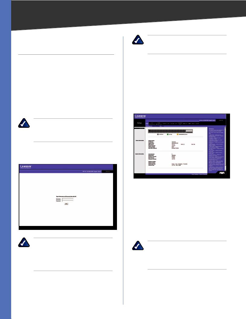
Open your web browser and enter 192.168.1.254 into the Address field. Press the Enter key and the login screen appears.
Login Screen
NOTE: The default IP address of the device is 192.168.1.254. If you have modified this address, enter the correct IP address. The device should be on the same subnet as the management station used to configure the device.
The first time you open the Web-based Utility, enter admin in the User Name field, and leave the Password field blank. Click the OK button. For security purposes, it is recommended that you set a new password on the System Password screen. the System Password screen.
Advanced Configuration
NOTE: After configuring values using the Webbased Utility, you may be required to refresh the page to see the updated configuration.
The first screen that appears is the Setup Summary screen. Twelve main tabs are accessible from the Web-based Utility: Setup, Port Management, VLAN Management, Statistics, ACL, Security, QoS (Quality of Service), Spanning Tree, Multicast, SNMP, Admin, and Logout. Click one of the main tabs to view additional tabs.
Setup > Summary
The Summary screen provides device and system information about the Switch.
Setup > Summary
At the top of the Summary screen, an image of the Switch‘s front panel provides the following color-coded status information for the Switch’s Ethernet ports:
Green Indicates a connection. Grey Indicates no connection.
Orange Indicates the port has been closed down by the administrator.
When you click a port’s LED, the statistics for that port are displayed.
NOTE: The port colors in the Summary screen are not related to the colors of the LEDs on the Switch’s ports. The port LEDs display different status information, as described in Chapter 2: Product Overview.
Device Information
System Name Displays the name for the Switch, if one has been entered on the Setup tab’s Network Settings screen.
WebView Switches |
20 |
Chapter 5 |
Advanced Configuration |
IP Address The IP address assigned to the Switch. This setting can be configured from the Setup tab’s Network Settings screen.
Subnet Mask The Subnet Mask assigned to the Switch. This setting can be configured from the Setup tab’s
Network Settings screen.
DNS Servers The IP address of your ISP’s server that translates the names of websites into IP addresses. This setting can be configured from the Setup tab’s Network Settings screen.
Default Gateway The IP address of the gateway router between the Switch and management stations on other network segments. This setting can be configured from the Setup tab’s Network Settings screen.
Address Mode Specifies whether IP functionality is enabled via manual configuration (Static) or Dynamic Host Configuration Protocol (DHCP). This setting can be configured from the Setup tab’s Network Settings screen.
Base MAC Address Displays the MAC address of the Switch.
System Information
Serial Number Displays the Switch’s Serial Number. Model Name Displays the model name of the Switch.
HardwareVersion Displays the Switch’s current hardware version.
Boot Version Displays the current boot version of the Switch.
Firmware Version Displays the Switch’s software version.
System Location Displays the location of the system if it has been defined. This setting can be configured from the Setup tab’s Network Settings screen.
System Contact The name of the administrator appears here,ifonehasbeendefined.Thissettingcanbeconfigured from the Setup tab’s Network Settings screen.
System Up Time Displays the length of time that has elapsed since the Switch was last reset.
Current Time Displays the current time. This setting can be configured from the Setup tab’s Time screen.
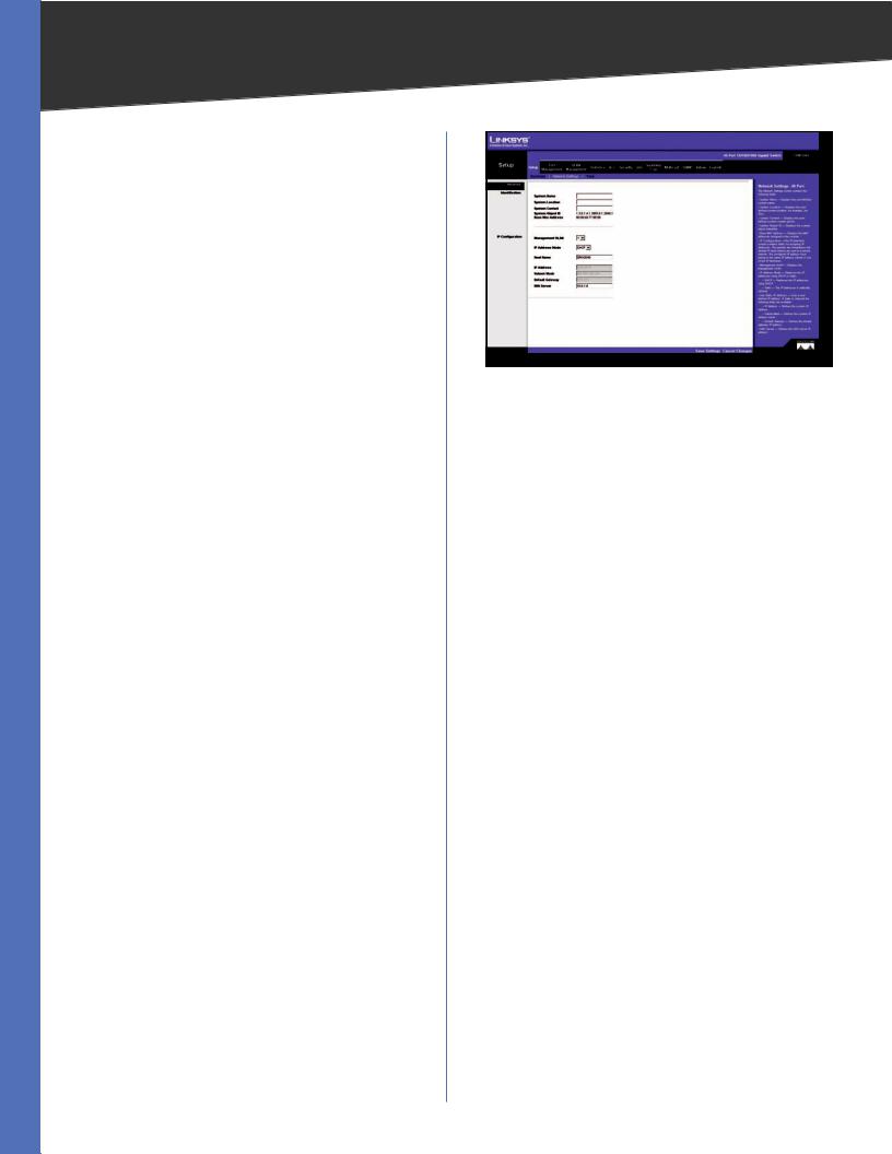
Setup > Network Settings
The Network Settings screen allows you to assign DHCP or static IP settings to interfaces and assign default gateways.
Setup > Network Settings
Identification
System Name Specifies the name of the Switch. Enter the name into the text field provided. By default, a system name is not defined.
System Location This field is used to enter a description of where the Switch is physically located, such as 3rd Floor.
System Contact Enter the name of the administrator responsible for the system.
System Object ID Displays the system object identifier.
Base MAC Address Displays the physical address of the Switch.
IP Configuration
Management VLAN This drop-down menu allows you to select the Management VLAN.
IP Address Mode Specifies whether IP functionality is enabled via manual configuration (Static) or Dynamic Host Configuration Protocol (DHCP). Select Static or DHCP from the drop-down menu. Selecting Static will allow you to enter a static IP address, subnet mask and default gateway using the text field provided. The default setting is DHCP.
Host Name Enter the DHCP Host Name here.
IP Address If you are using a static IP address, enter the IP address here.
Subnet Mask If you are using a static IP address, enter the subnet mask for the currently configured IP address.
Default Gateway If you are using a static IP address, enter the IP address of the default gateway.
DNS Server If you are using a static IP address, enter the IP address of the DNS server. A second DNS address can be specified in the additional text field provided.
WebView Switches |
21 |
Chapter 5 |
Advanced Configuration |
Click Save Settings to save your changes. Click Cancel Changes to cancel your changes.
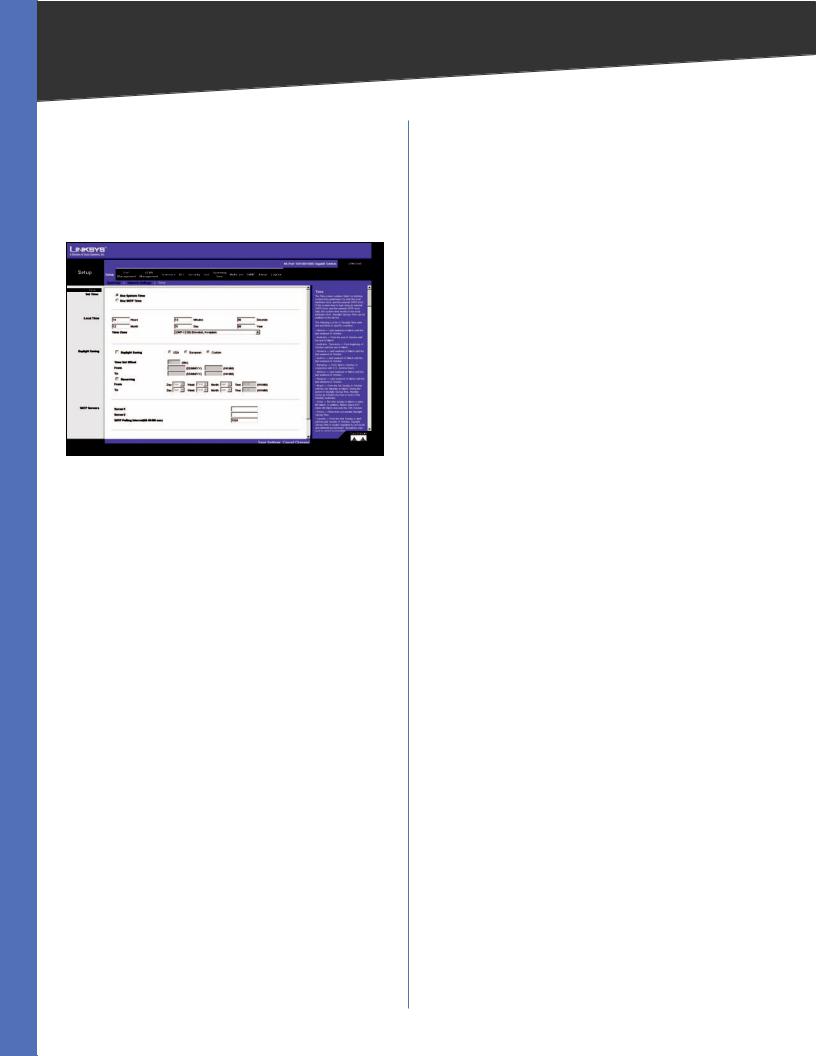
Setup > Time
The Time screen allows you to configure the time settings for the Switch.
Setup > Time
Set Time
Use System Time Select this option to use the local hardware clock.
Use SNTP Time Select this option to synchronize the time to an SNTP (Simple Network Time Protocol) server.
Local Time
Hours Enter the two-digit hour here. Minutes Enter the two-digit minutes here. Seconds Enter the two-digit seconds here. Month Enter the two-digit month here. Day Enter the two-digit day here.
Year Enter the last two digits of the year here (for example, 08 instead of 2008).
Time Zone Select your time zone from the drop-down menu.Time zones are identified by the difference between Greenwich Mean Time (GMT) and local time.
Daylight Saving
Daylight Saving Select Daylight Saving to enable it on the Switch. If the Switch should use US daylight savings, then select USA. If the Switch should use EU daylight savings, then select European. If it should use another kind of daylight savings, then select Custom and complete the From and To fields.
Time Set Offset For non-US and European countries, specify the amount of time for daylight savings. The default is 60 minutes. The range is (1–1440).
From If you selected Other for the Daylight Saving setting, enter the date and time when daylight savings begins.
To If you selected Other for the Daylight Saving setting, enter the date and time when daylight savings ends.
Recurring If you selected Other for the Daylight Saving setting and daylight savings has the same start and end dates and times every year, select Recurring.
From If you selected Recurring, enter the date and time when daylight savings begins.
To If you selected Recurring, enter the date and time when daylight savings ends.
SNTP Servers
Server1 Enter the primary SNTP server here. Server2 Enter a secondary SNTP server here.
SNTP Polling Interval (60–86400 sec) Specify the amount of time (in seconds) before the Switch polls the SNTP server. The default value is every 1024 seconds (approx. 17 minutes).
Click the Save Settings button to save your changes or click Cancel Changes to discard the information.
WebView Switches |
22 |
Loading...