


DUAL 824
SUPERVISED WIRELESS
SECURITY CONTROL PANEL
Installation & Programming Instructions
USA & Canada (800) 421-1587 & (800) 392-0123
(760) 438-7000 - Toll Free FAX (800) 468-1340
www.linearcorp.com
INTRODUCTION
CONGRATULATIONS for selecting Linear's DUAL 824 Security System. The Model DUAL 824P Control Panel and the Model DUAL 824KP Keypad incorporate many advanced and sophisticated features. The system can be expanded and customized to fit the installation's specific needs.
The DUAL 824P Control Panel and its accessories are designed and manufactured by the oldest wireless security company in North America. You can look ahead to many years of reliable service with this Control Panel and its accessories.
Many insurance companies offer discounts on homeowners and renters policies when a security system is installed. Discount credits vary with different companies and generally increase in savings with an increase in the level of protection. Inform the user to ask their insurance agent about savings available.
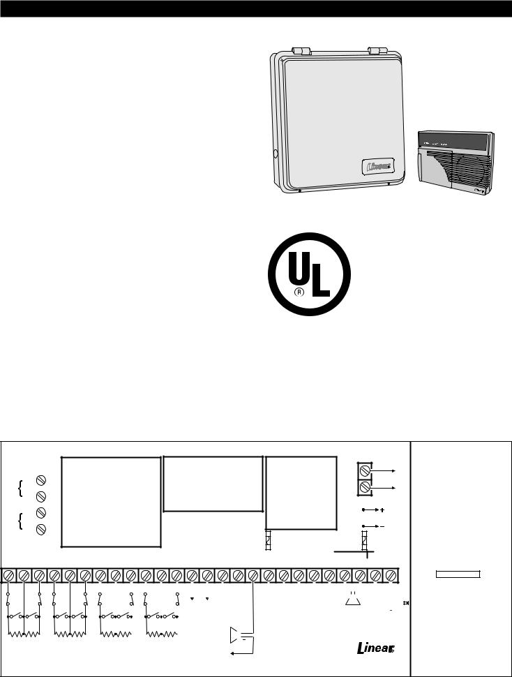
The DUAL 824P Control Panel is UL Listed. For a UL smoke alarm system, there must be at least one smoke detector programmed into the Control Panel to meet National Fire Protection Association (NFPA) Rule 72 Chapter 2 and UL 217 requirements. Many insurance companies require these conditions to be met to qualify for a discount. Only use the Model DXS-73 smoke detector with this Control Panel for a UL smoke alarm system.
NOTE: Some cities and municipalities may require an alarm system permit. Check with the local authorities before installing this system.
In this manual, the bullets preceding the text help to define the information. For example:
This symbol indicates a feature.
This symbol is for lit indications or system sounds.
This symbol is for important notes.
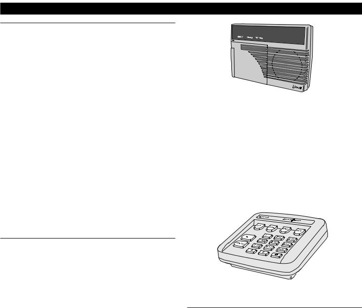
DUAL 824 SYSTEM
CONTROL PANEL |
KEYPAD |
MODEL DUAL 824P |
MODEL DUAL 824KP |
UL Listed as a Single Station Smoke Detector Accessory, also suitable as a Household BurglarAlarm System Control Unit. UL Category CCN UTGT & NBSX
|
|
|
USOC JACKS: |
|
|
|
|
|||||||||
|
|
|
RJ31X, RJ38X |
|
|
|
|
|||||||||
|
|
|
|
|
|
|
TELEPHONE |
|||||||||
|
|
|
|
|
|
|
RED |
|
|
|
|
RING |
||||
|
Incoming |
|
|
|
|
|
|
|
|
|
||||||
|
|
|
|
|
|
|
|
|
|
|
|
|
|
|||
Phone Line |
|
GREEN |
|
|
|
|
TIP |
|||||||||
|
|
|
|
|
|
|
|
|
||||||||
|
|
|
|
|
|
|
|
|
|
|
|
|
||||
|
|
|
|
|
|
GRAY |
|
|
|
|
R1 |
|||||
|
|
|
|
|
|
|
|
|
|
|||||||
|
Local |
|
|
|
|
|
|
|
|
|
||||||
|
|
|
|
|
|
|
|
|
|
|
|
|
|
|||
Telephones |
|
BROWN |
|
|
|
|
T1 |
|||||||||
|
|
|
|
|
|
|
|
|
||||||||
|
|
|
|
|
|
|
|
|
|
|
|
|
||||
|
|
|
|
|
|
|
|
|
|
|
|
|
|
|
|
|
|
|
|
|
|
|
|
|
|
|
|
|
|
||||
|
LOOP |
COM LOOP |
LOOP |
|||||||||||||
|
||||||||||||||||
1 |
|
2 |
|
3 |
|
|
||||||||||
|
|
|
|
|
|
|
|
|
|
|
|
|
|
|
|
|
|
|
|
|
|
|
|
|
|
|
|
|
|
|
|
|
|
WARNING:
1)MISCONNECTIONS MAY CAUSE DAMAGE TO CONTROL PANEL ELECTRONICS
2)DO NOT REVERSE BATTERY LEADS
3)TO PREVENT RISK OF ELECTRICAL SHOCK, DISCONNECT TELCO JACK BEFORE SERVICING THIS CONTROL PANEL
4)FOR CONTINUED PROTECTION AGAINST FIRE, REPLACE ONLY WITH SAME TYPE AND RATING OF FUSES
CAUTION:
1)NO USER SERVICABLE PARTS INSIDE
2)RISK OF FIRE AND ELECTRICAL SHOCK, ROUTE WIRES AWAY FROM INTERNAL COMPONENTS
3)REMOVE AC POWER BEFORE CONNECTING TRANSFORMER, BATTERY, OR REPLACING FUSES
Fire protection must follow NFPA Standard No. 72 (National Fire Protection Association, Batterymarch Park, Quincy, MA 02269). Printed information describing proper installation, operation, testing, maintenance, evacuation planning, and repair service is to be provided with this equipment.
IMPORTANT:
1)USE UL LISTED CABLE FOR ALL CONNECTIONS
2)WEEKLY TESTING IS REQUIRED TO ENSURE PROPER OPERATION OF THIS SYSTEM
3)DO NOT CONNECT AC POWER TO A RECEPTACLE CONTROLLED BY A SWITCH
4)CONNECTION OF THE FIRE ALARM SIGNAL TO A FIRE ALARM HEADQUARTERS OR A CENTRAL STATION SHALL BE PERMITTED ONLY WITH THE APPROVAL OF THE LOCAL AUTHORITY HAVING JURISDICTION. THE BURGLAR ALARM SIGNAL SHALL NOT BE CONNECTED TO A POLICE EMERGENCY NUMBER.
AUXILIARY FUSE
TYPE 2AG, 1 AMP
HARDWIRED LOOP INPUTS |
|
|
|
|
|
|
|
|
|
|
|
|
|
|
|
|
|
|
OUTPUTS |
|
|
|
|
|
|
|
|
|
|
|
|
|
KEYPAD |
||||||||||||||||
COM LOOP |
LOOP COM |
LOOP |
LOOP |
COM LOOP |
H/A |
H/A |
RLY |
RLY |
RLY |
+12 |
KPD |
KPD |
KPD |
KPD |
|||||||||||||||||||||||||||||||||||
4 |
|
5 |
|
|
|
6 |
|
7 |
|
8 |
|
- |
|
+ |
|
COM |
N/C |
N/O |
VDC |
+ |
|
- |
|
CLK |
DAT |
||||||||||||||||||||||||
|
|
|
|
|
|
|
|
|
|
|
|
|
|
|
|
|
|
|
|
|
|
|
|
|
|
|
|
|
|
|
|
|
|
|
|
|
|
|
|
|
|
|
|
|
|
|
|
|
|
|
|
|
|
|
|
|
|
|
|
|
|
|
|
|
|
|
|
|
|
|
|
|
|
|
|
|
|
|
|
|
|
|
|
|
|
|
|
|
|
|
|
|
|
|
|
|
|
|
|
ANTENNA
ANT
To internal antenna wires or to Model LA-P external antenna kit
SHIELD
BACKUP BATTERY
RED (+) |
|
CONNECT TO |
|||||||
|
Battery wires |
12 VDC/4AH |
|||||||
|
GEL CELL |
||||||||
Charging voltage: 13.8 VDC |
|||||||||
BATTERY |
|||||||||
BLACK (-) |
|
||||||||
|
Normal battery |
||||||||
|
|
|
|||||||
|
|
|
|
life should |
|||||
|
|
|
exceed 3 years |
||||||
|
|
BATTERY FUSE |
|||||||
|
|
TYPE 2AG, 3 AMP |
|||||||
|
|
XFRMR |
|
|
|
|
|||
KPD |
KPD |
AC |
AC |
|
|
||||
|
|||||||||
SPK+ |
SPK - |
|
|
|
|
|
|
|
|
|
|
|
|
|
|
|
|
|
|
|
|
|
|
|
|
|
|
|
|
LOOP 1 |
LOOP 2 |
LOOP 3 |
LOOP 4 |
N.C. |
N.C. |
N.C. |
N.C. |
N.O. |
N.O. |
N.O. |
N.O. |
2.2k |
2.2k |
2.2k |
2.2k |
E.O.L. |
E.O.L. |
E.O.L. |
E.O.L. |
RESISTOR RESISTOR |
RESISTOR RESISTOR |
||
LOOP RESPONSE TIME: 400 mS
MADE IN CHINA 454
|
LOOP 5 |
|
LOOP 6 |
|
|
LOOP 7 |
|
LOOP 8 |
|
|
|
|
|
|
|
|
|
|
|
|
|
|
|
ORANGE |
|
|
|
|
|
|
|
|
|
|
|
|
|
|
|
|
|
|
||
|
|
|
|
|
|
|
|
|
|
|
|
|
|
|
|
|
|
|
|
|
|
|
|
|
|
|
|
|
|
|
|
|
|
|
|
|
|
|||||||
|
|
|
|
|
|
|
|
|
|
|
|
|
|
|
|
Rated 12 volts, |
|
POWER |
|
RED |
|
BLACK |
WHITE |
|
|
|
|
|
|
|
|
|
|
|
|
|
|
|
|
|||||
|
N.C. |
|
N.C. |
|
N.C. |
|
N.C. |
|
|
|
|
ALARM RELAY |
|
AUXILIARY |
|
|
|
|
|
|
|
|
|
|
|
|
|
|
|
|
|
|
|
|
|
|
|
|||||||
|
|
|
|
|
|
|
|
|
|
|
|
AUTOMATION |
|
1 amp maximum |
|
OUTPUT |
|
|
|
|
|
|
|
|
|
|
|
|
|
|
|
|
|
|
|
|
|
|
|
|||||
|
|
|
|
|
|
|
|
|
|
|
|
|
OUTPUT |
|
|
|
|
12 VDC at 1 Amp |
|
|
DUAL 824KP |
|
|
MODEL RSM-2 |
|
|
|
|
|
|||||||||||||||
|
|
|
|
|
|
|
|
|
|
|
|
Current limited |
|
|
|
|
|
|
|
|
|
|
|
|
|
|||||||||||||||||||
|
|
|
|
|
|
|
|
|
|
|
|
EXTERNAL SIREN |
|
maximum |
|
HARDWIRED KEYPAD |
|
VOICE RESPONSE |
|
|
|
|
|
|||||||||||||||||||||
|
|
|
|
|
|
|
|
|
|
|
|
|
switched |
|
|
|
|
|
SPEAKER |
|
|
|
|
|
||||||||||||||||||||
|
|
|
|
|
|
|
|
|
|
|
|
|
|
12 VDC at 1 Amp |
|
|
|
|
|
ONE OR TWO |
|
|
|
|
|
TRANSFORMER |
||||||||||||||||||
|
N.O. |
|
N.O. |
|
|
N.O. |
|
N.O. |
|
+12 VDC, 40 mA |
|
|
|
|
|
|
|
|
8 Ohm - 2 Watts |
|
|
|||||||||||||||||||||||
|
|
|
|
|
|
|
maximum |
|
|
|
|
|
|
|
|
|
||||||||||||||||||||||||||||
|
|
|
|
|
|
voltage source |
|
|
|
|
|
|
UNITS ALLOWED |
|
|
|
|
16VAC, 1.25A |
||||||||||||||||||||||||||
|
|
|
|
|
|
|
|
|
|
|
|
|
|
|
|
|
|
|
|
|
|
|
|
|
|
|
|
|
|
|
|
|
|
|
|
|||||||||
|
|
|
|
|
|
|
|
|
|
|
|
See instructions |
|
|
|
|
|
|
|
|
|
KEYPAD WIRING |
|
|
|
|
|
|
|
|
|
|
|
|
|
|
|
Connect to |
||||||
|
|
|
|
|
|
|
|
|
|
|
|
for output options |
|
|
|
|
|
|
|
|
|
4-conductor 22 AWG wire |
|
|
|
|
|
|
|
|
|
|
|
|
|
|
|
24hr. 120VAC, |
||||||
|
2.2k |
|
2.2k |
|
2.2k |
|
2.2k |
|
|
|
|
|
|
|
|
|
|
|
|
|
|
|
|
|
|
|
|
|
|
|
|
60 Hz Outlet |
||||||||||||
|
|
|
|
|
|
|
|
|
|
|
|
|
Up to 100 feet for all keypads used allowed |
|
|
|
|
|
|
|
|
|
|
|
|
|
||||||||||||||||||
|
E.O.L. |
|
E.O.L. |
|
E.O.L. |
|
E.O.L. |
|
|
|
|
|
|
|
|
|
|
|
|
|
|
|
|
|
|
|
|
|
|
|
|
|
|
|
|
|
|
|
|
|
||||
RESISTOR RESISTOR |
RESISTOR RESISTOR |
|
|
|
|
|
|
|
|
FOR INSTALLATION INSTRUCTIONS, |
|
|
|
|
|
|
|
|
|
|
|
|
|
|
|
|
||||||||||||||||||
|
|
|
|
|
|
|
|
|
|
|
|
|
|
|
|
|
|
|
|
|
|
|
|
|
|
|
|
|
|
|
|
|
|
|
|
|||||||||
MAXIMUM RECOMMENDED LOOP LENGTH: 500 FEET |
|
|
|
To any COM terminal |
|
REFER TO THE MANUAL SUPPLIED |
|
|
|
|
|
(760) 438-7000 • FAX (760) 438-7043 |
||||||||||||||||||||||||||||||||
|
|
|
|
|
|
|
|
|
|
|
|
|
|
|
|
WITH THIS PRODUCT |
|
|
|
|
USA & Canada (800) 421-1587 & (800) 392-0123 |
|||||||||||||||||||||||
|
|
|
|
|
|
|
DUAL 824 WIRING DIAGRAM |
|
|
|
|
|
||||||||||||||||||||||||||||||||
|
|
|
|
|
|
|
|
|
|
|
|
|
|
|
|
|
|
|
|
|
|
|
|
|
|
www.linearcorp.com |
||||||||||||||||||
|
|
|
|
|
|
|
|
|
|
|
|
|
|
|
|
|
|
|
|
|
|
|
|
|
|
|
|
|
|
|
|
|
|
|
|
Toll Free FAX (800) 468-1340 |
||||||||
LINEAR LLC
RESIDENTIAL SECURITY RECEIVER MODEL: DUAL 824
PART # SSC00056 FREQUENCY: 315 MHz
POWER SUPPLY: 16 VAC, 1.25A
This device complies with FCC Part 15 and IC Canada Rules and Regulations. Operation is subject to the following two conditions: (1) This device may not cause harmful interference and (2) this device must accept any interference received, including interference that may cause undesired operation.
Complies with Part 68, FCC Rules.
FCC Registration Number: EF4HKG-31823-AL-E Ringer Equivalence Number: 1.7B
CANADIAN REGULATORY INFORMATION
IC ID 1078-102-556A
Complies with IC RSS 210
En conformité avec IC CNR 210.
Warranty Expiration Date:

TABLE OF CONTENTS
1. THE DUAL 824 SECURITY SYSTEM. . . . . . . . . . . . . . . . . . . . . . . . . . . . . . . . . . . . . . . 2
CONTROL PANEL. . . . . . . . . . . . . . . . . . . . . . . . . . . . . . . . . . . . . . . . . . . . . . . . . 2 DOOR/WINDOW SENSORS. . . . . . . . . . . . . . . . . . . . . . . . . . . . . . . . . . . . . . . . . 3 WIRELESS KEYPAD . . . . . . . . . . . . . . . . . . . . . . . . . . . . . . . . . . . . . . . . . . . . . . . 3 SMOKE DETECTOR . . . . . . . . . . . . . . . . . . . . . . . . . . . . . . . . . . . . . . . . . . . . . . . 3
REMOTE CONTROLS. . . . . . . . . . . . . . . . . . . . . . . . . . . . . . . . . . . . . . . . . . . . . . 3
GLASS BREAK DETECTOR. . . . . . . . . . . . . . . . . . . . . . . . . . . . . . . . . . . . . . . . . 3 PANIC BUTTONS . . . . . . . . . . . . . . . . . . . . . . . . . . . . . . . . . . . . . . . . . . . . . . . . . 3 BILL TRAP. . . . . . . . . . . . . . . . . . . . . . . . . . . . . . . . . . . . . . . . . . . . . . . . . . . . . . . 3 PASSIVE INFRARED MOTION DETECTOR. . . . . . . . . . . . . . . . . . . . . . . . . . . . . 3
2. SECURITY SYSTEM FLOOR PLAN . . . . . . . . . . . . . . . . . . . . . . . . . . . . . . . . . . . . . . . 4
EXAMPLE SYSTEM . . . . . . . . . . . . . . . . . . . . . . . . . . . . . . . . . . . . . . . . . . . . . . . 4 DESIGN THE INSTALLATION . . . . . . . . . . . . . . . . . . . . . . . . . . . . . . . . . . . . . . . . 4 3. OVERVIEW OF KEYPADS . . . . . . . . . . . . . . . . . . . . . . . . . . . . . . . . . . . . . . . . . . . . . . . 5 HARDWIRED KEYPAD . . . . . . . . . . . . . . . . . . . . . . . . . . . . . . . . . . . . . . . . . . . . . 5
WIRELESS KEYPAD . . . . . . . . . . . . . . . . . . . . . . . . . . . . . . . . . . . . . . . . . . . . . . . 5
ABOUT SENSOR STATUS SUPERVISION . . . . . . . . . . . . . . . . . . . . . . . . . . . . . 5 4. HARDWIRED KEYPAD FEATURES. . . . . . . . . . . . . . . . . . . . . . . . . . . . . . . . . . . . . . . . 6 5. CONTROL PANEL FEATURES . . . . . . . . . . . . . . . . . . . . . . . . . . . . . . . . . . . . . . . . . . . 7 6. CONTROL PANEL INSTALLATION . . . . . . . . . . . . . . . . . . . . . . . . . . . . . . . . . . . . . . . . 8
SYSTEM LOCATION . . . . . . . . . . . . . . . . . . . . . . . . . . . . . . . . . . . . . . . . . . . . . . . 8
WALL MOUNTING. . . . . . . . . . . . . . . . . . . . . . . . . . . . . . . . . . . . . . . . . . . . . . . . . 8 EXTERNAL ANTENNA . . . . . . . . . . . . . . . . . . . . . . . . . . . . . . . . . . . . . . . . . . . . . 8 HARDWIRED KEYPAD INSTALLATION . . . . . . . . . . . . . . . . . . . . . . . . . . . . . . . . 9 HARDWIRED LOOP WIRING . . . . . . . . . . . . . . . . . . . . . . . . . . . . . . . . . . . . . . . 10
ARM/DISARM KEY STATION WIRING . . . . . . . . . . . . . . . . . . . . . . . . . . . . . . . . 10
EXTERNAL ALARM SIREN CONNECTION . . . . . . . . . . . . . . . . . . . . . . . . . . . . 11
TELEPHONE LINE CONNECTION . . . . . . . . . . . . . . . . . . . . . . . . . . . . . . . . . . 11 AUTOMATION OUTPUT CONNECTION . . . . . . . . . . . . . . . . . . . . . . . . . . . . . . 12
VOICE RESPONSE MODULE . . . . . . . . . . . . . . . . . . . . . . . . . . . . . . . . . . . . . . 12 CONTROL PANEL POWER CONNECTION . . . . . . . . . . . . . . . . . . . . . . . . . . . . 13 BACKUP BATTERY INSTALLATION . . . . . . . . . . . . . . . . . . . . . . . . . . . . . . . . . 13
7. BASIC CONTROL PANEL PROGRAMMING. . . . . . . . . . . . . . . . . . . . . . . . . . . . . . . . 14 CREATE THE MASTER USER CODE . . . . . . . . . . . . . . . . . . . . . . . . . . . . . . . . 14
PROGRAM THE HARDWIRED LOOPS . . . . . . . . . . . . . . . . . . . . . . . . . . . . . . . 15 PROGRAM THE WIRELESS SENSORS . . . . . . . . . . . . . . . . . . . . . . . . . . . . . . 15 PROGRAMMING DIFFERENT SENSOR TYPES. . . . . . . . . . . . . . . . . . . . . . . . 16
8. BASIC SENSOR INSTALLATION. . . . . . . . . . . . . . . . . . . . . . . . . . . . . . . . . . . . . . . . . 18 DXS-10 WIRELESS KEYPAD . . . . . . . . . . . . . . . . . . . . . . . . . . . . . . . . . . . . . . . 18
DXS-31 & DXS-32 DOOR/WINDOW SENSORS . . . . . . . . . . . . . . . . . . . . . . . . 19 TEST SENSORS . . . . . . . . . . . . . . . . . . . . . . . . . . . . . . . . . . . . . . . . . . . . . . . . . 19 9. CUSTOMIZING THE KEYPAD . . . . . . . . . . . . . . . . . . . . . . . . . . . . . . . . . . . . . . . . . . . 20
LABELING THE SENSOR LOCATIONS . . . . . . . . . . . . . . . . . . . . . . . . . . . . . . . 20 10. SYSTEM OPERATING MODES . . . . . . . . . . . . . . . . . . . . . . . . . . . . . . . . . . . . . . . . . . 21
OFF MODE . . . . . . . . . . . . . . . . . . . . . . . . . . . . . . . . . . . . . . . . . . . . . . . . . . . . . 21 CHIME MODE . . . . . . . . . . . . . . . . . . . . . . . . . . . . . . . . . . . . . . . . . . . . . . . . . . . 21 HOME MODE . . . . . . . . . . . . . . . . . . . . . . . . . . . . . . . . . . . . . . . . . . . . . . . . . . . 22
SECURE EXIT. . . . . . . . . . . . . . . . . . . . . . . . . . . . . . . . . . . . . . . . . . . . . . . . . . . 22 HOME INSTANT MODE . . . . . . . . . . . . . . . . . . . . . . . . . . . . . . . . . . . . . . . . . . . 22
MANUAL BYPASSING OF SENSORS . . . . . . . . . . . . . . . . . . . . . . . . . . . . . . . . 22 AWAY MODE . . . . . . . . . . . . . . . . . . . . . . . . . . . . . . . . . . . . . . . . . . . . . . . . . . . . 23 MANUAL BYPASSING OF SENSORS . . . . . . . . . . . . . . . . . . . . . . . . . . . . . . . . 23
TEST MODE . . . . . . . . . . . . . . . . . . . . . . . . . . . . . . . . . . . . . . . . . . . . . . . . . . . . 24 11. SYSTEM TROUBLE INDICATIONS . . . . . . . . . . . . . . . . . . . . . . . . . . . . . . . . . . . . . . . 25 CONTROL PANEL POWER . . . . . . . . . . . . . . . . . . . . . . . . . . . . . . . . . . . . . . . . 25 WIRELESS SENSOR LOW BATTERIES . . . . . . . . . . . . . . . . . . . . . . . . . . . . . . 25 SENSOR RADIO TROUBLE . . . . . . . . . . . . . . . . . . . . . . . . . . . . . . . . . . . . . . . . 25 12. CUSTOMIZING THE SYSTEM . . . . . . . . . . . . . . . . . . . . . . . . . . . . . . . . . . . . . . . . . . . 26
ADDING SENSORS TO THE SYSTEM. . . . . . . . . . . . . . . . . . . . . . . . . . . . . . . . 26
REMOVING SENSORS FROM THE SYSTEM . . . . . . . . . . . . . . . . . . . . . . . . . . 26 MAKING A SENSOR A 24-HOUR DOOR CHIME . . . . . . . . . . . . . . . . . . . . . . . 27 MAKING A SENSOR INTERIOR. . . . . . . . . . . . . . . . . . . . . . . . . . . . . . . . . . . . . 27 MAKING A SENSOR PERFORM A DIFFERENT FUNCTION . . . . . . . . . . . . . . 28
13. ADVANCED PROGRAMMING . . . . . . . . . . . . . . . . . . . . . . . . . . . . . . . . . . . . . . . . . . . 29
SETUP MODE . . . . . . . . . . . . . . . . . . . . . . . . . . . . . . . . . . . . . . . . . . . . . . . . . . . 29 CHANGING A SENSORS SUPERVISION . . . . . . . . . . . . . . . . . . . . . . . . . . . . . 30 CHANGING A SENSORS RESTORE REQUIREMENTS . . . . . . . . . . . . . . . . . . 30 ENTRY DELAY TIME. . . . . . . . . . . . . . . . . . . . . . . . . . . . . . . . . . . . . . . . . . . . . . 30
EXIT DELAY TIME. . . . . . . . . . . . . . . . . . . . . . . . . . . . . . . . . . . . . . . . . . . . . . . . 30
BURGLARY SIREN TIME . . . . . . . . . . . . . . . . . . . . . . . . . . . . . . . . . . . . . . . . . . 30 EMERGENCY SIREN TIME . . . . . . . . . . . . . . . . . . . . . . . . . . . . . . . . . . . . . . . . 30 FIRE SIREN TIME . . . . . . . . . . . . . . . . . . . . . . . . . . . . . . . . . . . . . . . . . . . . . . . . 31 AUTOMATION OUTPUT TIME . . . . . . . . . . . . . . . . . . . . . . . . . . . . . . . . . . . . . . 31
REMOTE CONTROL & HARDWIRE ARMING LEVEL . . . . . . . . . . . . . . . . . . . . 31
REMOTE CONTROL & HARDWIRE DISARMING LEVEL . . . . . . . . . . . . . . . . . 31 ENTRY DELAY BEEPS . . . . . . . . . . . . . . . . . . . . . . . . . . . . . . . . . . . . . . . . . . . . 31 EXIT DELAY BEEPS . . . . . . . . . . . . . . . . . . . . . . . . . . . . . . . . . . . . . . . . . . . . . . 31 SILENT BURGLARY ALARMS . . . . . . . . . . . . . . . . . . . . . . . . . . . . . . . . . . . . . . 32
SILENT EMERGENCY ALARMS . . . . . . . . . . . . . . . . . . . . . . . . . . . . . . . . . . . . 32
DISABLING QUICK ARMING . . . . . . . . . . . . . . . . . . . . . . . . . . . . . . . . . . . . . . . 32 AUTOMATIC RESTORAL OF BYPASSED SENSORS . . . . . . . . . . . . . . . . . . . . 32 AUTOMATIC BYPASSING OF OPEN SENSORS . . . . . . . . . . . . . . . . . . . . . . . . 32 AUTOMATION OUTPUT MODE DURING ALARM . . . . . . . . . . . . . . . . . . . . . . . 33
AUTOMATION ACTIVATION TONE . . . . . . . . . . . . . . . . . . . . . . . . . . . . . . . . . . . 33
REMOTE CONTROL & HARDWIRE ARM/DISARM CHIRP . . . . . . . . . . . . . . . . 33 AUTOMATION OUTPUT ON DURING AND AFTER ALARM . . . . . . . . . . . . . . . 33 AUTOMATION OUTPUT ON DURING ALARM. . . . . . . . . . . . . . . . . . . . . . . . . . 33 AUTOMATION OUTPUT WHILE ARMED . . . . . . . . . . . . . . . . . . . . . . . . . . . . . . 34
AUTOMATION OUTPUT DURING EXIT/ENTRY DELAYS . . . . . . . . . . . . . . . . . 34
AUTOMATION OUTPUT POLARITY. . . . . . . . . . . . . . . . . . . . . . . . . . . . . . . . . . 34
REMOTE ACCESS PASSWORD . . . . . . . . . . . . . . . . . . . . . . . . . . . . . . . . . . . . 34 DURESS CODE . . . . . . . . . . . . . . . . . . . . . . . . . . . . . . . . . . . . . . . . . . . . . . . . . 34
MASTER USER CODE . . . . . . . . . . . . . . . . . . . . . . . . . . . . . . . . . . . . . . . . . . . . 34 ADDING ADDITIONAL USER CODES . . . . . . . . . . . . . . . . . . . . . . . . . . . . . . . . 35 REMOVING ADDITITIONAL USER CODES. . . . . . . . . . . . . . . . . . . . . . . . . . . . 35
CONTROL PANEL MASTER RESET . . . . . . . . . . . . . . . . . . . . . . . . . . . . . . . . . 35 14. COMMUNICATOR PROGRAMMING . . . . . . . . . . . . . . . . . . . . . . . . . . . . . . . . . . . . . . 36
SETUP MODE . . . . . . . . . . . . . . . . . . . . . . . . . . . . . . . . . . . . . . . . . . . . . . . . . . . 36 GENERAL COMMUNICATOR OPTIONS . . . . . . . . . . . . . . . . . . . . . . . . . . . . . . 37 COMMUNICATOR ENABLE . . . . . . . . . . . . . . . . . . . . . . . . . . . . . . . . . . . . . . . . 37
2-WAY AUDIO . . . . . . . . . . . . . . . . . . . . . . . . . . . . . . . . . . . . . . . . . . . . . . . . . . . 37 VOICE RESPONSE. . . . . . . . . . . . . . . . . . . . . . . . . . . . . . . . . . . . . . . . . . . . . . . 37
REMOTE LOCKOUT . . . . . . . . . . . . . . . . . . . . . . . . . . . . . . . . . . . . . . . . . . . . . . 37 CALL LIMITER. . . . . . . . . . . . . . . . . . . . . . . . . . . . . . . . . . . . . . . . . . . . . . . . . . . 38 DIALING DELAY . . . . . . . . . . . . . . . . . . . . . . . . . . . . . . . . . . . . . . . . . . . . . . . . . 38
DIALING METHOD . . . . . . . . . . . . . . . . . . . . . . . . . . . . . . . . . . . . . . . . . . . . . . . 38 COMMUNICATOR REPORTING OPTIONS . . . . . . . . . . . . . . . . . . . . . . . . . . . . 39
REPORTING FORMAT . . . . . . . . . . . . . . . . . . . . . . . . . . . . . . . . . . . . . . . . . . . . 39 CALL ROUTING . . . . . . . . . . . . . . . . . . . . . . . . . . . . . . . . . . . . . . . . . . . . . . . . . 39 ACCOUNT NUMBER . . . . . . . . . . . . . . . . . . . . . . . . . . . . . . . . . . . . . . . . . . . . . 40
PRIMARY TELEPHONE NUMBER . . . . . . . . . . . . . . . . . . . . . . . . . . . . . . . . . . . 40 SECONDARY TELEPHONE NUMBER . . . . . . . . . . . . . . . . . . . . . . . . . . . . . . . . 40
SUPERVISORY OR PAGER TELEPHONE NUMBER . . . . . . . . . . . . . . . . . . . . 40 TELEPHONE NUMBER DELAYS AND SPECIAL CHARACTERS . . . . . . . . . . . 40 REPORT CONTROL PANEL TROUBLE . . . . . . . . . . . . . . . . . . . . . . . . . . . . . . . 41
REPORT FORCE ARMING. . . . . . . . . . . . . . . . . . . . . . . . . . . . . . . . . . . . . . . . . 41 OPENING AND CLOSING REPORTS . . . . . . . . . . . . . . . . . . . . . . . . . . . . . . . . 41 POINT ID REPORTING. . . . . . . . . . . . . . . . . . . . . . . . . . . . . . . . . . . . . . . . . . . . 41 COMMUNICATOR REPORTING CODES . . . . . . . . . . . . . . . . . . . . . . . . . . . . . . 42 GENERAL REPORTING CODES . . . . . . . . . . . . . . . . . . . . . . . . . . . . . . . . . . . . 42 SYSTEM REPORTING CODES . . . . . . . . . . . . . . . . . . . . . . . . . . . . . . . . . . . . . 43
FORCE ARMING REPORTING CODE . . . . . . . . . . . . . . . . . . . . . . . . . . . . . . . . 43
DURESS REPORTING CODE . . . . . . . . . . . . . . . . . . . . . . . . . . . . . . . . . . . . . . 43 4 BY 2 FORMAT POINT ID REPORTING CODES . . . . . . . . . . . . . . . . . . . . . . . 44 4 BY 2 FORMAT POINT ID ALARM REPORT CODES. . . . . . . . . . . . . . . . . . . . 44 4 BY 2 FORMAT POINT ID TROUBLE REPORT CODES . . . . . . . . . . . . . . . . . 44
IMPORTANT INFORMATION . . . . . . . . . . . . . . . . . . . . . . . . . . . . . . . . . . . . . . . . . . . . . . . 46
LINEAR LIMITED WARRANTY . . . . . . . . . . . . . . . . . . . . . . . . . . . . . . . . . . . . . . 46 WIRELESS PRODUCT NOTICE . . . . . . . . . . . . . . . . . . . . . . . . . . . . . . . . . . . . . 46 FCC NOTICE. . . . . . . . . . . . . . . . . . . . . . . . . . . . . . . . . . . . . . . . . . . . . . . . . . . . 46 FCC TELEPHONE RULES AND REGULATIONS. . . . . . . . . . . . . . . . . . . . . . . . 46 FIRE EVACUATION PLANNING . . . . . . . . . . . . . . . . . . . . . . . . . . . . . . . . . . . . . 46 INDUSTRY CANADA NOTICES . . . . . . . . . . . . . . . . . . . . . . . . . . . . . . . . . . . . . 46
1
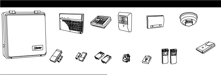
1.THE DUAL 824 SECURITY SYSTEM
|
|
|
|
|
DXS-91 GLASS |
|
DXS-73 |
|
|
|
|
DXS-10 |
|
SMOKE DETECTOR |
|||
|
DUAL 824KP |
|
DXS-54 |
BREAK DETECTOR † |
||||
|
|
WIRELESS |
|
|
||||
|
HARDWIRED |
|
PIR |
|
|
|
|
|
|
|
KEYPAD |
|
|
|
|
||
|
KEYPAD |
|
|
|
|
|
|
|
|
|
|
|
|
|
|
|
|
|
|
|
|
|
|
|
|
DXS-81 |
DUAL 824P |
|
|
|
|
|
|
|
BILL TRAP † |
|
|
|
|
|
|
|
|
|
CONTROL |
DXS-31 |
DXS-32 MINI |
DXT-41 & DXT-42 |
DXS-62A |
DXT-61A |
DXT-21 & DXT-23 |
† NOTE: These accessories |
|
PANEL |
DOOR/WINDOW |
DOOR/WINDOW |
REMOTES |
REMOTE |
REMOTE † |
REMOTES † |
are not listed by UL. |
|
|
SENSOR |
SENSOR |
||||||
|
|
|
|
|
|
|
||
CONTROL PANEL
The DUAL 824P Control Panel is the heart of the system. It monitors all of the system's wireless sensors, hardwired loops, and controls the alarm sirens and Model DUAL 824KP hardwired keypads.
The Control Panel constantly monitors the condition of the system's sensors and hardwired contacts, displaying which protected doors and windows are open or closed. If an alarm occurs, the keypads display which sensor(s) caused it. When a sensor has a low battery, the keypads display which sensor needs a new battery. Sensors that send hourly status transmissions keep the Control Panel informed of their operating condition.
Up to eight different custom user codes can be used to operate the system. For security, a user code must be entered to disarm (turn off) the system. The system can be armed (turned on) by entering a user code, or with the unique “Quick Arm” feature. The five restricted user codes and the special page alert user code can only arm and disarm the system, no programming changes (except changing user and duress codes) are allowed. The master user code is allowed to program the Control Panel, and a duress code can be selected for emergency disarming of the system with a duress report to the Central Station. The page alert user code can dial a pager number to inform the pager wearer when the system is disarmed.
The Control Panel's memory will retain the user codes and all of the system's programming, even during a total power loss. An optional backup battery can be installed to power the system during short power failures.
The built-in digital communicator connects the Control Panel to a Central Alarm Monitoring Station through the telephone. With a monitored system, the central station can dispatch authorities in case of burglary, fire or other emergency. The central station can also call family, friends, neighbors, or anyone else designated on a custom call list. System arming (closing) and disarming (opening) reports by user can also be sent.
Each sensor can report directly to the Central Station using the digital communicator's Point ID feature. If a sensor triggers an alarm or experiences supervisory trouble, a unique report code can be sent for immediate identification of the event.
The optional Model VB-2 digital voice response module can be installed in the Control Panel. The VB-2 module provides three exciting features: 2-way audio monitoring capability at the Central Station through the communicator, local voice prompts from the keypad's speaker (with Model RSM-2 speaker/microphone kit installed), and voice prompted remote system control using in-house or off-site pushbutton telephones.
The system has 24-hour capabilities that are always ready to operate, even when the system is disarmed. They can be triggered by buttons on the hardwired keypads, a wireless keypad, portable remote controls, carbon monoxide detectors, and smoke detectors. Pressing the EMERGENCY or FIRE button for two seconds will cause an immediate siren and call the central station. IMPORTANT: For personal emergency use only. Not for use as a UL Listed Medical Alert System.
The Control Panel's Environmental feature is active 24-hours and can be triggered with sensors connected to devices such as water flow detectors, over/under temperature sensors, flood sensors, etc. The Environmental feature activates the chime annunciator without sounding the siren. The Environmental feature does not send communicator reports.
An Automation Output in the Control Panel provides an easy way to connect external devices to the Control Panel. The output is fully programmable to activate on a variety of conditions, such as when the system is armed, during alarms, and during exit/entry delays. The Automation Output can connect to lighting control modules, relays, noisemakers, and indicators. The Control Panel's and wireless keypad's  key and any system sensors can control the Automation Output.
The Control Panel can be programmed locally using its own keypad or remotely, over the telephone, using Linear's Model RA-2400 Remote Access software program. The RA-2400 upload/download program is a Windows™ application that runs on a personal computer and communicates with the Control Panel through a modem, connected directly to the panel, or through the telephone line.
2
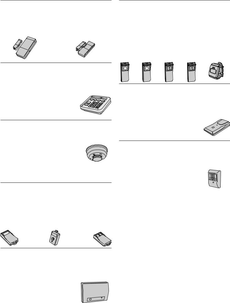
DOOR/WINDOW SENSORS
The DXS-31 and DXS-32 sensors monitor doors and windows. They send radio signals to the Control Panel. One type of signal is sent when the door or window is opened, and a different type of signal is sent when the door or window is closed. If the system is armed, a sensor can trigger the Control Panel's burglary siren when its door or window is opened. Both sensors are supervised, send hourly status reports, and monitor their battery condition.
DXS-32
DXS-31
WIRELESS KEYPAD
The DXS-10 wireless keypad is used to operate the system remotely. It can be placed in a convenient spot so the user doesn't have to go to the hardwired keypad to operate the system. The wireless keypad can also trigger the emergency or fire siren and actuate the Automation Output. Pressing will cause the hardwired keypad(s) to sound Beeps corresponding to the current
operating mode. The DXS-10 is supervised, it sends hourly status reports and monitors its battery condition. IMPORTANT: For personal emergency use only. Not for use
as a UL Listed Medical Alert System.
SMOKE DETECTOR
The DXS-73 is a high quality smoke detector with a built-in radio transmitter. As soon as smoke is detected, the unit will sound its local noisemaker. Then, 20 seconds after the local noisemaker sounds, the transmitter sends an alarm signal to the Control Panel.The alarm signal will be repeated every 20 seconds as long
as smoke is still present. A restoral signal will be sent when the smoke detection chamber clears. The DXS-73 is supervised, it sends hourly status reports, and monitors its battery condition.
NOTE: A Model DXS-73 Smoke Detector is required to create a UL Listed smoke alarm system. See Page 26 for details on adding a smoke detector sensor to the system.
REMOTE CONTROLS
The DXT-41, DXT-61 single-button and DXT-23, DXT-42 multi-button remote controls can be used to remotely arm and disarm the system. The DXT-42’s left button will arm and the right button will disarm the system. Pressing both buttons simultaneously will trigger the emergency siren. Alternately the Control Panel can be programmed to respond to the DXT-42 by arming and disarming with the left button, and activating the automation output with the right button. These transmitters can also be programmed to activate various other Control Panel zones. These transmitters are not supervised.
DXT-41 |
DXT-42 |
|
DXT-61‡
GLASS BREAK DETECTOR
The DXS-91 is a glass break detector with an audio sound discriminator and a built-in radio transmitter. The unit “listens” for the sound of breaking glass. When glass breakage is detected, the unit sends an alarm signal to the Control Panel. The DXS-91 is supervised, it sends hourly status reports and monitors its battery condition.
DXS-91‡
PANIC BUTTONS
The DXT-21, DXS-21 single-button, and DXT-23, DXS-23 two-button transmitters can be used as portable “panic buttons”. Pressing the front or top button on the DXT-21 or DXS-21 at any time will trigger the emergency siren. Pressing both front buttons simultaneously on the DXT-23 or DXS-23 at any time will trigger the emergency siren. These transmitters can be programmed to activate various other system functions.The DXT-21 and DXT-23 transmitters are not supervised. The DXS-21 and DXS-23 transmitters are supervised. The DXS-62A transmitter is typically used as a portable “panic button”. Pressing the button on a DXS-62A at any time will trigger the emergency siren. This transmitter can send hourly status signals and low battery signals if the battery is low.
DXT-21‡  DXS-21‡
  DXT-23‡
  DXS-23‡
  DXS-62A
BILL TRAP
The DXS-81 bill trap can be used with the Control Panel in nonUL small commercial hold-up installations. The unit is concealed in a cash drawer under a stack of currency, with a single “bait” bill secured in its money clip. During a hold-up, the cashier removes the stack of currency along with the “bait” bill. When a “bait” bill is removed, the transmitter sends a signal to the Control Panel. Four additional signals are sent within the first minute
after the “bait” bill is removed. When the “bait” bill is replaced, a restore signal is sent. The DXS-81 is supervised, it can send hourly status reports (optional) and monitors its battery condition.
PASSIVE INFRARED MOTION DETECTOR
The DXS-54 is a passive infrared (PIR) motion detector with a built-in radio transmitter. The PIR detects motion in its detection pattern by measuring the infrared emission levels of objects that it “sees”. If the infrared levels change quickly, as when a person moves across the detection pattern, the PIR will recognize the
change as an intrusion and send an alarm signal to the Control Panel. An alarm will be triggered if the system is in the Away Mode. The DXS-54 is supervised, it sends hourly status reports and monitors its battery condition.
‡ NOTE: These accessories not listed by UL
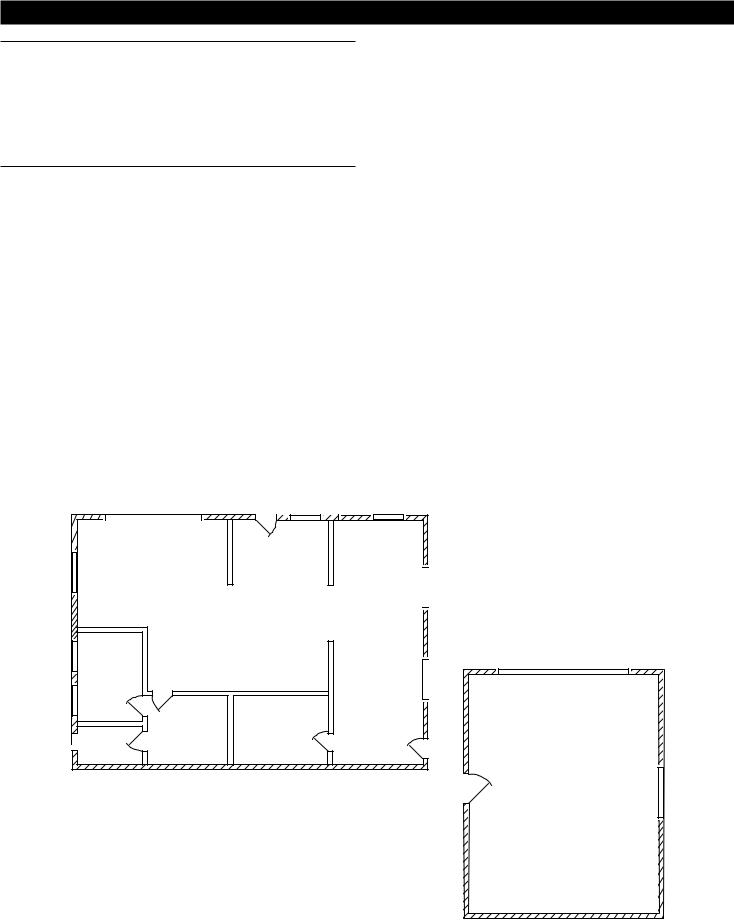
2.SECURITY SYSTEM FLOOR PLAN
EXAMPLE SYSTEM
The example shows a typical DUAL 824 system.
Any or all of the accessories shown can be used.
A total of 24 sensors can be used with each Control Panel. Each wireless sensor, hardwired loop, and wireless keypad used occupies a sensor location.
DESIGN THE INSTALLATION
1.Draw a floor plan for the installation.
2.Consider the security needs of the premises.
3.Determine which doors and windows are vulnerable to intrusion.
4.Figure which interior areas an intruder might go to if unlawful entrance is gained.
5.Indicate locations for door/window sensors, interior motion detectors, wireless and hardwired keypads, glass break detectors and external siren speakers.
6.Decide on a centralized location for the security Control Panel.
ES |
|
|
|
|
MD |
GB |
S |
S |
MS |
|
|
HK |
|
|
|
LIVING |
ENTRY |
|
|
S |
|
|
|
|
|
|
|
|
|
|
|
|
|
MS |
|
|
|
|
KITCHEN |
S BED |
|
DINING |
|
CO |
|
|
|
|
|
S |
|
|
|
MS |
|
|
|
HK |
|
|
SD |
|
|
|
S BATH |
BED |
|
S |
|
|
|
|||
DEN |
|
|
CP |
|
|
|
|
|
NOTE: IN NEW CONSTRUCTION, NFPA 72 REQUIRES A SMOKE DETECTOR LOCATED INSIDE EACH BEDROOM AS WELL AS A SMOKE DETECTOR ON EACH LEVEL.
CP - CONTROL PANEL
HK - HARDWIRED KEYPAD
S - DOOR/WINDOW SENSOR WK - WIRELESS KEYPAD MD - MOTION DETECTOR ES - EXTERNAL SIREN
SD - SMOKE DETECTOR
CO - CARBON MONOXIDE DETECTOR GB - GLASS BREAK SENSOR
MS - HARDWIRED MAGNETIC SWITCH
S
WK
S
GB
GARAGE
MD
Example Residential Security System Floor Plan
4
3.OVERVIEW OF KEYPADS
HARDWIRED KEYPAD
One or two hardwired keypads can be used for controlling the system.
Three system status indicators:
READY, ARMED, & TROUBLE
Three system supervisory indicators:
POWER, BATTERIES, & RADIO
Five system mode indicators:
OFF, CHIME, HOME, AWAY & TEST
24 system sensor indicators.
Location inside beauty cover for supplied sensor identification labels.
Press  to activate the automation output.
Pressing clears the keypad.
Pressing for two seconds sounds the mode Beeps from the hardwired keypad(s).
Off Mode: 1 “Gong”.
Chime Mode: 1 “Gong” & 1 “Beep”.
Home Mode: 1 “Gong” & 2 “Beeps”.
Away Mode: 1 “Gong” & 3 “Beeps”.
Test Mode: 1 “Gong” & 4 “Beeps”.
Emergency and fire alarm can be triggered from the keypad at any time.
UL NOTE: For personal emergency use only. Not for use as a UL Listed Medical Alert System.
WIRELESS KEYPAD
For controlling the system remotely.
Green operation light.
Internal 9-volt battery is monitored by the Control Panel.
Keypad's beeper will buzz during transmissions when the battery is low.
Up to 3 years battery life (depends on frequency of activation). (UL tested for 1 year minimum.)
Sends hourly status reports to the Control Panel.
Press  to activate the automation output.
Pressing clears the keypad.
Pressing for two seconds sounds the mode Beeps from the hardwired keypad(s).
Off Mode: 1 “Gong”.
Chime Mode: 1 “Gong” & 1 “Beep”.
Home Mode: 1 “Gong” & 2 “Beeps”.
Away Mode: 1 “Gong” & 3 “Beeps”.
Test Mode: 1 “Gong” & 4 “Beeps”.
Emergency and fire alarm can be triggered from the wireless keypad at any time.
UL NOTE: For personal emergency use only. Not for use as a UL Listed Medical Alert System.
HARDWIRED
KEYPAD
WIRELESS
KEYPAD
ABOUT SENSOR STATUS SUPERVISION
All DXS Format sensors transmit hourly status reports. All DXT Format sensors do not transmit hourly status reports. Both sensor formats can be used with the system.
When a sensor is programmed into the Control Panel, the system will set the sensor as non-supervised or supervised. Sensors set as non-supervised are not expected to send hourly status reports. Sensors set as supervised are expected to send hourly status reports. If a status report is not received in 8 hours from a sensor set as supervised, the RADIO indicator will flash.
When sensors are programmed into the Control Panel, ALL
STATIONARY SENSORS ARE SET AS SUPERVISED, ALL PORTABLE SENSORS ARE SET AS NON-SUPERVISED.
If stationary DXT Format sensors have been programmed into the Control Panel, be sure to change their setting to non-supervised to prevent RADIO indications. This will not prevent low battery monitoring.
If portable DXS Format sensors have been programmed into the Control Panel, and the installation requires supervision for specific portable sensor(s), change the selected portable sensors setting to supervised.
After programming the sensors, if changes are required, refer to “Changing a Sensors Supervision” on Page 30 for details on changing the way a sensor’s supervision is set.
5
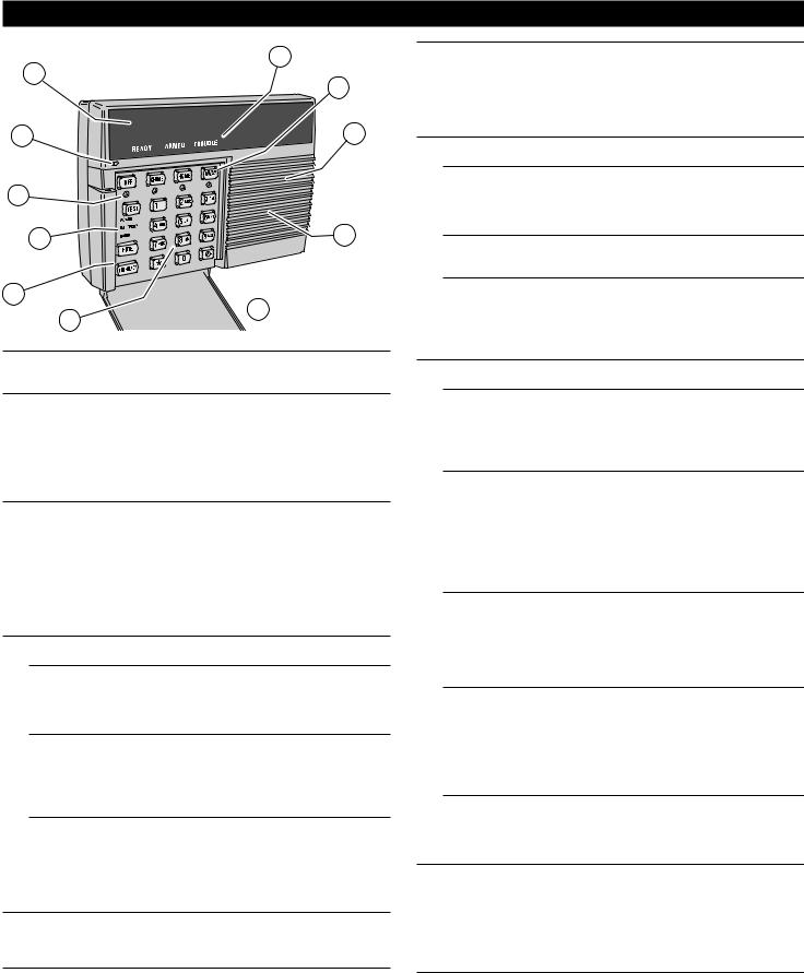
4.HARDWIRED KEYPAD FEATURES
7 |
8 |
|
9 |
||
|
||
6 |
10 |
|
5 |
|
|
4 |
11 |
3
 1
1
2
1BEAUTY COVER
The beauty cover snaps open and shut to hide the keypad’s keys, mode and supervisory indicators, and the sensor location labeling area.
2KEYPAD
Backlit keys for easy viewing in low light conditions.
For entering the user's user code (numerically or alphabetically).
Used when programming system options.
Press  to activate the Automation Output.
Press to clear keypad if the wrong key is pressed.
Press for two seconds to view sensor battery and supervisory status (see BATTERIES and RADIO indicator description).
324-HOUR BUTTONS
Pressing FIRE for two seconds sounds the fi re siren and sends a “fi re” message to a central monitoring station through the digital communicator (if the system is monitored).
Pressing EMERGENCY for two seconds sounds the emergency siren and sends an “emergency” message to a central monitoring station through the digital communicator (if the system is monitored).
Both work even when system is disarmed.
IMPORTANT: For personal emergency use only. Not for use as a UL Listed Medical Alert System.
4SYSTEM SUPERVISORY INDICATORS
Shows the current status of the system.
POWER LIGHT
Glows when AC power is on.
Blinks when AC power is off and backup battery is installed.
Blinks when the backup battery is low, recharging or missing.
Off when AC power is off and no backup battery is installed (system disabled).
BATTERIES LIGHT
Blinks when one or more sensors have a low battery.
Press for two seconds to view sensor status. Sensor status indicator for any sensor with a low battery will light along with the BATTERIES indicator.
Switch to Test Mode after replacing the sensor battery and completely test the system (see Test Mode). Switching to Test Mode clears the low battery indication.
RADIO LIGHT
Blinks when one or more sensors have not reported status during the eight hour status time period.
Press for two seconds to view sensor status. Sensor status indicator for any sensor that has not reported in will light along with the TROUBLE indicator.
Switch to Test Mode after servicing the sensor and completely test the system (see Test Mode). Switching to Test Mode clears the trouble indication.
5MODE INDICATORS
The indicators next to the mode keys light to show the current system mode.
HOME indicator will blink during Secure Exit and Home Instant modes.
AWAY indicator will blink during the exit delay in the Away Mode.
6MICROPHONE (OPTIONAL)
Location for the high sensitivity microphone included with the Model RSM-2 speaker/microphone kit.
Detects room audio when communicator is reporting to the Central Station in 2-way audio mode (Model VB-2 digital voice response module and RSM-2 speaker/microphone kit must be installed).
7SENSOR STATUS INDICATORS
Blacked-out sensor status indicators are only visible when lit.
Indicate the status of each of the system's wireless sensors and hardwired loops.
Indicators show which doors and windows are open.
Indicators fl ash to display sensors that have caused an alarm.
Stick-on labels are provided to identify the custom sensor locations.
8SYSTEM STATUS INDICATORS
Shows the current status of the system.
READY LIGHT
Lights when all system sensors are closed.
Shows that the system is ready to be armed.
The system can be armed without the READY indicator being lit, if sensors are bypassed either manually or automatically.
ARMED LIGHT
Blinks during the exit delay.
Lights when the system is fully armed.
TROUBLE LIGHT
Lights when the system has detected supervisory trouble.
Supervisory trouble can be caused by power, sensor low battery, or sensor radio supervision conditions.
Press for one second then view the system supervisory and status indicators to determine the origin of the trouble.
9MODE BUTTONS
Used to operate the system.
OFF
Off Mode disarms the system.
Switching to Off Mode stops the alarm siren.
Multiple Beeps sound and sensor status indicators fl ash if an alarm has occurred.
Multiple Beeps mean caution. AN INTRUDER MAY STILL BE PRESENT.
CHIME
Chime Mode disarms the system.
Switching to Chime Mode stops the alarm siren.
Multiple Beeps sound and sensor status indicators fl ash if an alarm has occurred.
Multiple Beeps mean caution. AN INTRUDER MAY STILL BE PRESENT.
Chime Mode is for monitoring doors and windows.
Use this mode as an “automatic door chime” when at home.
Opening any protected door or window causes the keypad(s) to “ding-dong”.
HOME
Home Mode arms the perimeter sensors, but not the interior sensors.
Use this mode when anyone is staying behind.
Interior motion detectors and interior door sensors are not armed.
Home secure mode makes all delayed perimeter sensors instant.
Secure exit mode starts an exit delay while remaining in Home Mode.
Re-entering during the exit delay restarts the exit delay (one time only).
AWAY
Away Mode arms the entire system.
Use this mode when leaving home.
Door sensors set for delayed will have a time delay that allows the user to leave and enter the premises without sounding the alarm.
Re-entering during the exit delay restarts the exit delay (one time only).
Entry Delay Beeps warn the user to disarm the system before the siren starts.
TEST
Test Mode is for testing the system sensors.
All sensor status lights blink when the Test Mode is entered.
Each sensor status light will stop blinking when its sensor is tested.
Hold the TEST button down to test all of the keypad's indicator lights.
10SOUNDER
Makes unique sounds for burglary, fi re and emergencies.
Alarm sirens stop automatically after fi ve minutes.
Sounds advisory tones to confi rm keystrokes from the keypad.
Sounds mode selection tones.
Sounds alarm memory tones.
Beeps when Automation Output is activated.
The Control Panel has terminals available for an external siren.
11SPEAKER (OPTIONAL)
Location for the speaker included with the Model RSM-2 speaker/microphone kit.
Sounds voice operating prompts and audio from the Central Station (Model VB-2 digital voice response module and Model RSM-2 required).
6

5.CONTROL PANEL FEATURES
|
|
8 |
|
9 |
|
|
7 |
|
|
|
|
|
|
|
10 |
|
|
|
|
|
|
|
|
|
|
6 |
|
|
11 |
5 |
|
|
|
|
|
|
|
|
12 |
|
|
|
|
|
|
|
|
|
|
4 |
|
|
|
|
|
|
3 |
|
|
|
|
2 |
|
|
|
|
|
|
1 |
13 |
14 |
|
|
|
|
||
|
|
|
|
|
1BATTERY FUSE
Type 2AG, 3-amp fuse for the backup battery.
If the keypad's POWER light is fl ashing and the optional backup battery is installed and charged, check this fuse.
WARNING: For continued protection against the risk of fire, replace only with the same type and rating of fuse.
2CONDUIT KNOCKOUTS
Four cabinet knockouts are provided for wiring using conduit.
The 3/4" knockouts fi t standard 3/4" conduit fi ttings.
3WIRING ACCESS SLOT
Provides access for wiring through a hole in the mounting wall.
Route cables for power, telephone, external speaker, etc. through this slot.
4MAIN TERMINAL BLOCK
Terminals for hardwired loop inputs.
Terminals for Automation Output to connect to an automation controller.
Terminals for external relay output for “dry” contacts (Form C, normally open/ normally closed, 1 amp @ 24 volts maximum).
Terminals for fused auxiliary 12 volt output and common ground.
Terminals for connection to one or two Model DUAL 824KP keypads.
Terminals for connection to the plug-in AC transformer.
5AUXILIARY FUSE
Type 2AG, 1-amp fuse.
Protects the auxiliary power output and siren driver circuit.
Fuse will blow when load exceeds 1 amp total.
WARNING: For continued protection against the risk of fire, replace only with the same type and rating of fuse.
6TELEPHONE TERMINAL BLOCK
Provides telephone connections for the digital communicator.
Provides telephone connection for voice prompted telephone remote control (optional VB-2 digital voice response module required).
Provides seized ring and tip connections for local telephone instruments. Communicator will disconnect local telephones while on-line.
7WALL-MOUNT KEYHOLE SLOTS
Four slots used when mounting Control Panel to the wall.
Used as a template for the Control Panel when it is mounted to the wall.
8DIGITAL VOICE RESPONSE MODULE (OPTIONAL)
The Model VB-2 gives the Control Panel's digital communicator listen-only, manual 2-way and full duplex 2-way audio capability with the Central Station.
The module allows remote command of the system using a standard pushbutton telephone, on or off site.
The module provides optional voice prompts from the keypad(s) (Model RSM-2 speaker/microphone kit required for each keypad).
9ANTENNA KNOCKOUT
A cabinet knockout is provided for mounting an external antenna connector.
For an external antenna, use Linear's Model LA-P antenna kit.
The antenna kit can also be used to connect the Control Panel to co-ax for a remote antenna.
10ANNUNCIATOR VOLUME CONTROL
Varies the volume of the advisory tones that come from the keypad(s) speaker when the Model RSM-2 speaker/microphone kit is installed in the keypad.
Does not affect keypad's sirens (they are always full volume).
11RADIO TEST POINTS
Used to monitor the Control Panel's radio receiver during troubleshooting.
Provides connection for an audio amplifi er to listen to the receiver's output.
Helpful to determine sources of radio interference.
12ANTENNA TERMINALS
Antenna and shield (ground) terminals for receiving signals from the system's sensors.
Pre-wired to the Control Panel's internal wire dipole antenna.
Alternately connects to the Model LA-P local whip and remote antenna kit.
13OPTIONAL BACKUP BATTERY
Space for 12-volt, 4 amp/hour backup battery. (Highly recommended.)
Backup battery is automatically charged and monitored by the Control Panel.
Backup battery can power the Control Panel for up to 6 hours.
UL NOTE: Normal estimated battery life should be 3 to 4 years.
14REMOVABLE CABINET COVER
The cabinet cover can be removed for easy system wiring and setup.
Two screws secure cabinet cover when closed.
An optional cabinet lock can be installed for additional security.
7
6.CONTROL PANEL INSTALLATION
SYSTEM LOCATION
NOTE: Wireless sensor signals must be able to reach the Control Panel.
Try to centrally locate the Control Panel.
Keep Control Panel away from large metal appliances.
Maximum recommended sensor range is 400 feet (system tested at 1000 feet).
NOTE: If you don't use the wireless keypad, a hardwired keypad should be easily accessible to the usual entrance.
When the Control Panel is set in the Away Mode, the user has 30 seconds to switch to Off Mode before the burglary siren sounds.
NOTE: Make sure a hardwired keypad is in a place where the alarm can be heard during the night hours.
Optional remote external sirens (up to 150 feet from the Control Panel) can be used to make alarms louder and remote the sound location.
1.Locate the Control Panel near a 115 VAC outlet that's not controlled by a light switch.
2.Locate the Control Panel near a telephone outlet (if using the digital communicator).
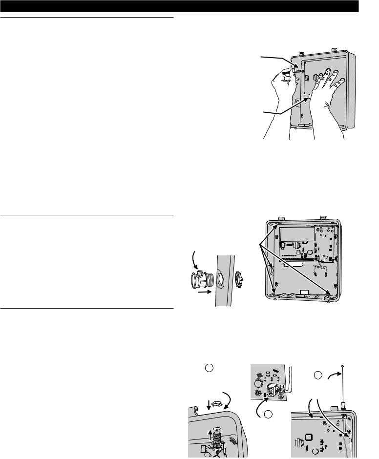
WALL MOUNTING
1.Use the Control Panel's case bottom as a template and mark the locations for the four mounting screws.
2.Mark the wiring access slot if the wiring is being routed from behind the cabinet.
3.Use a hole saw to cut out the location for the wiring access slot (if used) or punch out selected cabinet wiring knockouts for conduit wiring.
4.Use four screws and appropriate screw anchors to mount the unit to the wall.
EXTERNAL ANTENNA
Linear's Model LA-P antenna kit can be used with the DUAL 824P Control Panel to replace the standard internal antenna.
The antenna can be mounted on the cabinet, or the kit can be used to connect to co-ax for a remote antenna.
1.Remove the two standard white antenna wires attached to the ANT and SHIELD terminals.
2.Punch out the antenna knockout.
3.Mount the antenna connector in the antenna knockout.
4.Route the antenna co-ax down to the Control Panel's antenna connector.
5.Connect the antenna's co-ax center conductor to the ANT terminal.
6.Connect the antenna's co-ax shield to the SHIELD terminal.
7.Route the two antenna ground wires as shown.
USE THE CASE BOTTOM
AS A TEMPLATE TO MARK
THE FOUR KEYHOLE
MOUNTING HOLES
FOR RECESSED WIRING,
MARK WIRING SLOT, THEN
CUT OUT HOLE WITH
DRYWALL SAW
FOR CONDIUT WIRING, PUNCH OUT REQUIRED KNOCKOUTS AND INSTALL 3/4" CONDUIT HUBS IN HOLES
1
PUNCH OUT ANTENNA KNOCKOUT AND INSTALL LA-P ANTENNA CONNECTOR INTO HOLE
2
CONNECT CO-AX
SHIELD TO SHIELD
TERMINAL AND CO-AX
CENTER CONDUCTOR
TO ANT TERMINAL
3
INSTALL THE WHIP ANTENNA AND ROUTE THE TWO GROUND WIRES AS SHOWN
8
HARDWIRED KEYPAD INSTALLATION
One or two Model DUAL 824KP keypads can be used with the DUAL 824P Control Panel (one keypad is included in the DUAL 824 system package).
The keypad is supplied with a short wiring harness and connector.
1.Use a flat blade screwdriver to open the keypad case. Identify the keypad internal components.
2.Set the keypad select jumper to KEYPAD 1 if this is the first, or only, keypad installed. Set the jumper to KEYPAD 2 if this is the second keypad installed.
3.For a silent keypad, set the SOUNDER jumper to OFF.
4.Select an indoor location with easy wiring access to the Control Panel and use the keypad's mounting plate as a template to mark the mounting holes for the keypad.
5.Route 4-conductor 22 AWG (or larger) wire from the Control Panel to the keypad(s). Up to 100 feet of wire total can be used with this system. If installing two keypads, each keypad can be “home-run” or “daisy-chained”.
Note: If a Model VB-2 voice response module is going to be used with the system, in addition to the keypad’s four wires, route 2-conductor
shielded cable and 2-conductor 22 AWG wire from the Control Panel to the keypad(s) for the keypad’s microphone and speaker. When using two keypads and two microphones, each shielded microphone cable must be home run to the VB-2 terminal block.
6.If using the VB-2 voice response module, refer to the instructions supplied with the Model RSM-2 speaker/microphone kit for details on installing and wiring the keypad’s speaker and/or microphone.
7.Connect the 4-conductor wire to the Control Panel's keypad terminals, noting wire colors.
8.Noting wire colors, connect the keypad's wiring harness to the wire from the Control Panel.
9.Plug the keypad wiring harness into the keypad connector and snap the keypad case closed.
TWIST SCREWDRIVER
IN SLOTS TO OPEN
THE KEYPAD CASE
|
KEYPAD |
KEYPAD |
SELECT |
JUMPER |
CONNECTOR |
SOUNDER (KPD1 OR KPD2) |
||
RSM-2 KIT |
JUMPER |
RSM-2 KIT |
|
(ON OR OFF) |
|||
MICROPHONE |
|||
SPEAKER |
|
||
LOCATION |
|
LOCATION |
|
|
|
||
|
KEYPAD SELECT |
|
SOUNDER JUMPER |
JUMPER SET |
|
TO "KEYPAD 1" |
||
SET TO "ON" |
||
|
DEFAULT JUMPER POSITIONS
SOUNDER JUMPER |
SET KEYPAD SELECT |
|
CAN BE SET TO "OFF" |
||
JUMPER TO "KEYPAD 2" |
||
|
||
|
IF THIS IS THE 2ND KEYPAD |
COMPONENT
LOCATIONS
ALTERNATE JUMPER POSITIONS
NOTE: MAXIMUM RECOMMENDED
WIRE RUN IS 100 FEET COMBINED
TOTAL FOR ALL KEYPADS
MOUNT KEYPAD INDOORS
AT A CONVENIENT HEIGHT
AND LOCATION FOR THE USERS
USE THE MOUNTING PLATE
AS A TEMPLATE TO MARK
SCREW LOCATIONS
USE SCREWS AND ANCHORS
OR APPROPRIATE FASTENERS
TO AFFIX MOUNTING PLATE
THE MOUNTING PLATE IS ALSO
DESIGNED TO BE ATTACHED
TO A SINGLE-GANG OUTLET BOX
ROUTE 4-CONDUCTOR 22 AWG WIRE OR LARGER
FROM CONTROL PANEL TO KEYPAD
DUAL 824P
CONTROL PANEL
WHITE
KPD DAT
ORANGE
KPD CLK
BLACK
KPD
RED
KPD
TO DUAL 824KP
KEYPAD ROUTE WIRING CONNECTOR THROUGH MOUNTING PLATE HOLE
IF THE RSM-2 SPEAKER/MICROPHONE KIT IS GOING TO BE USED, RUN AN ADDITIONAL PAIR FOR THE SPEAKER AND A SHIELDED PAIR FOR THE MICROPHONE
WIRING |
|
|
HARNESS |
ALIGN TOP OF CASE FIRST, |
|
CONNECTOR |
||
THEN SNAP BOTTOM TOGETHER |
||
|
INSERT CONNECTOR INTO THE KEYED
SOCKET ON THE KEYPAD UNTIL IT
SNAPS TOGETHER
9
HARDWIRED LOOP WIRING
The DUAL 824 supports up to eight normally open/closed hardwired loops each with 2.2K end-of-line resistor supervision.
Each hardwired loop that is wired and programmed uses one sensor location.
Each hardwired loop can be programmed to any sensor number.
Each hardwired loop can be programmed as any sensor type, including arm/disarm toggle.
Four COM terminals are shared as loop returns for the eight loops.
Each hardwired loop has a 400 millisecond response time.
NOTE: For UL installations, use UL Listed cable for all hardwired loop wiring.
1.Route wiring from the Control Panel to each hardwired switch contact, sensor, or device. Route the wires through the wiring slot or through a knockout for conduit wiring.
NOTE: Maximum recommended hardwired loop length is 500 feet (250' out, and 250' back) for each loop. Maximum loop resistance (excluding the EOL resistor) is 100 ohms.
2.Connect the loop wires to LOOP # and COM terminals. For powered devices connect power wires to +12 VDC and any COM terminal.
3.On the sensor end, connect each normally closed sensor in series with the loop wires. Connect each normally open sensor in parallel with the loop wires. See wiring figure.
4.After the last sensor on the loop, connect a 2.2K end-of-line resistor across the loop.
NOTE: Before the hardwired loops will function, they will need to be programmed. This will be covered in the Basic Control Panel Programming section of this manual.
RUN LOOP WIRING BETWEEN THE CONTROL PANEL AND THE REMOTE
HARDWIRED SENSORS
4-CONDUCTOR
FOR HARDWIRED INFRAREDS 


2-CONDUCTOR
FOR MAGNETIC
CONTACTS
RUN 4-CONDUCTOR WIRE
 TO POWERED DEVICES


 RUN 2-CONDUCTOR WIRE
TO DEVICES NOT POWERED
FROM THE CONTROL PANEL
MAIN TERMINAL BLOCK
LOOP |
COM LOOP |
LOOP |
COM LOOP |
COM LOOP |
H/A |
H/A |
RLY |
RLY |
RLY |
+12 |
1 |
2 |
3 |
4 |
8 |
- |
+ |
COM |
N/C |
N/O |
VDC |
NORMALLY OPEN
SWITCHES (CONTACTS)
2.2K END-OF-LINE RESISTOR FOR EACH LOOP USED
NORMALLY CLOSED
SWITCHES (CONTACTS)
USE +12 VDC AND ANY COM TERMINAL TO POWER EXTERNAL DEVICES (1 AMP MAX.)
CONNECT EACH HARDWIRED INPUT TO A LOOP AND COM TERMINAL
FOR POWERED DEVICES, WIRE POWER LEADS TO +12 VDC AND ANY COMMON TERMINAL (OBSERVE POLARITY)
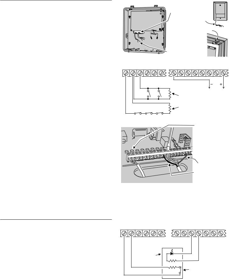
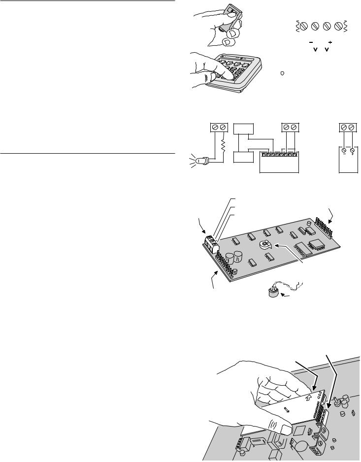
ARM/DISARM KEY STATION WIRING
Any of the hardwired loops can be used with a momentary keyswitch to arm and disarm the system.
1.Connect the loop as shown to the keyswitch and end-of-line resistor.
2.Connect an LED indicator from the switch plate to the H/A- and H/A+ terminals.
3.When programming the system, set the loop sensor function to “Type 9, Arm/Disarm Toggle” and set the Automation output to “Active while Armed”.
MAIN TERMINAL BLOCK
LOOP |
COM LOOP |
LOOP |
COM LOOP |
COM LOOP |
H/A |
H/A |
RLY |
RLY |
RLY |
1 |
2 |
3 |
4 |
8 |
- |
+ |
COM |
N/C |
N/O |
PROGRAM LOOP FOR |
|
PROGRAM AUTOMATION |
ARM/DISARM TOGGLE |
KEYSTATION |
OUTPUT FOR "ACTIVE |
(SENSOR TYPE 9) |
WHILE ARMED" |
|
LED WILL LIGHT |
|
|
WHEN SYSTEM |
LED |
|
IS ARMED |
|
|
|
|
|
|
470 OHM |
|
|
|
NORMALLY CLOSED, |
|
2.2K OHM |
SPRING RETURN, KEYSWITCH |
10
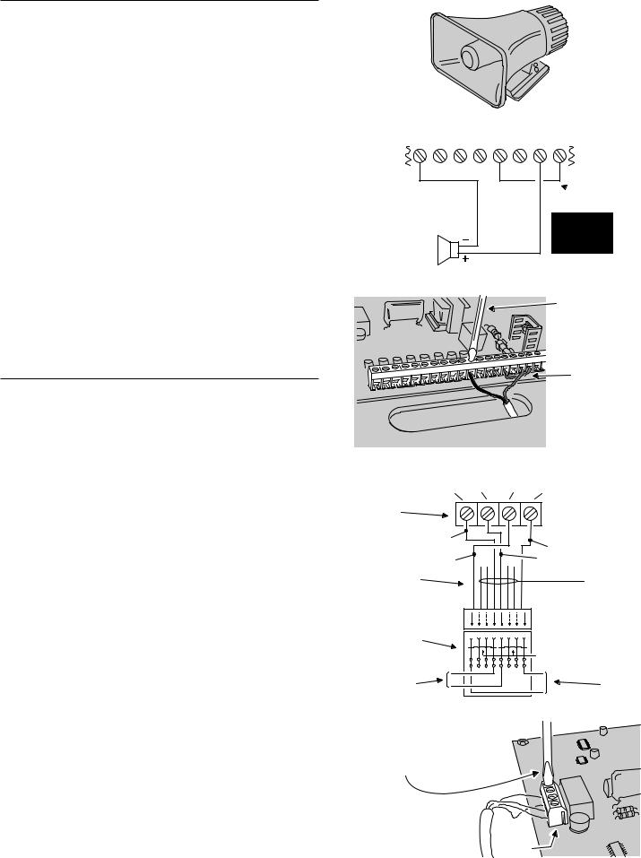
EXTERNAL ALARM SIREN CONNECTION
An external siren alerts occupants and neighbors with a loud siren during alarm.
Use a 12 volt, 1 amp maximum rated weatherresistant horn speaker with a built-in siren driver. Do not use a plain speaker without a siren driver.
NOTE: Connection of an electromechanical bell or motor bell is not recommended because of the radio interference generated when the bell is running.
UL NOTE: Only one external siren is allowed in UL installations.
1.Mount the external siren.
2.Route the wires from the external siren to the Control Panel.
3.Route the siren wires up through the wiring access slot or through a knockout when using conduit.
4.Connect a jumper wire from the +12 VDC terminal to the RLY COM terminal.
5.Connect the positive siren wire to the RELAY N/O terminal.
6.Connect the negative siren wire to one of the COM terminals.
NOTE: The relay contacts are isolated. Use the RLY N/O & RLY COM terminals alone to switch an externally powered load.
TELEPHONE LINE CONNECTION
Connect the Control Panel to the telephone line if the system is monitored, requires 2-way
audio, telephone remote command, or for remote programming with RA-2400 software.
Telephone RING & TIP terminals are for connection to the incoming telephone line.
Seized telephone ring & tip (R1 & T1) are for connection to local telephone sets. When the communicator activates, all the local telephone sets will be disconnected to prevent an off-hook telephone on the premises from blocking the communicator call.
1.Install a USOC RJ31-X or RJ38-X jack to the telephone system near the Control Panel.
2.Route an appropriate modular telephone line cord from the jack to the Control Panel.
3.Route the line cord through the Control Panel's wiring access slot or through a knockout for conduit wiring.
4.Connect the incoming telephone line wires to the Control Panel's telephone terminal block TIP and RING terminals.
5.Connect the local telephone set wires to the Control Panel's telephone terminal block T1 and R1 terminals.
When directly connecting (without a telephone line) to the DUAL 824 with the RA-2400 remote access software (Version 1.3 or later), disconnect the incoming telephone line and connect the modem to the panel's TIP and RING terminals (with the modem's red & green phone line wires). Press the EMERGENCY key while in Test Mode to cause the panel to connect to the modem.
EXTERNAL
ALARM
SIREN
MAIN TERMINAL BLOCK
COM LOOP |
H/A |
H/A |
RLY |
RLY |
RLY |
+12 |
|||||||||
8 |
- |
+ |
COM |
N/C |
N/O |
VDC |
|||||||||
|
|
|
|
|
|
|
|
|
|
|
|
|
|
|
|
|
|
|
|
|
|
|
|
|
|
|
|
|
|
|
|
|
|
|
|
|
|
|
|
|
|
|
|
|
|
|
|
|
|
|
|
|
|
|
|
|
|
|
|
|
|
|
|
EXTERNAL SIREN 12 VDC 1 AMP MAXIMUM
INSTALL WIRE
JUMPER TO PROVIDE
 POWER TO RELAY
CONTACTS
EXTERNAL
ALARM RELAY 12 VDC, 1 AMP MAXIMUM
CONNECT EXTERNAL
SIREN TO ALARM RELAY
TERMINALS
INSTALL A JUMPER WIRE BETWEEN THE +12 VDC AND RLY COM TERMINALS
TELEPHONE TERMINAL BLOCK
LINE |
LINE |
SEIZED |
SEIZED |
RING (R) |
TIP (T) |
RING (R1) |
TIP (T1) |
DUAL 824P |
|
|
|
TELEPHONE |
|
|
|
TERMINAL |
|
|
|
BLOCK |
|
|
|
RED |
|
|
BROWN |
|
|
|
|
GRAY |
|
|
GREEN |
8-PIN |
|
|
|
MODULAR |
|
|
|
PHONE CORD |
|
|
|
BLUE, ORANGE BLACK, AND YELLOW NOT USED
8-POSITION |
|
|
|
|
|
SHORTING BAR |
|
|
4 |
4 |
6 |
6 |
SHORT REMOVED |
||
USOC RJ31-X |
|
|
|
|
|
||
|
|
|
|
|
ON PLUG |
|
|
(OR RJ38-X) |
|
|
|
|
|
|
|
|
|
|
|
|
INSERTION |
|
|
JACK |
|
|
|
|
|
|
|
|
|
! " |
# $ % & |
|
|
||
|
R |
|
|
|
|
T1 |
TO LOCAL |
TO TELEPHONE |
|
|
|
|
|
|
|
T |
|
|
|
|
|
TELEPHONE |
|
NETWORK |
|
|
|
|
|
R1 |
SETS |
|
|
|
|
|
|
||
CONNECT INCOMMING AND
OUTGOING TELEPHONE LINES
TO THE TELEPHONE TERMINAL BLOCK
TELEPHONE
TERMINAL
BLOCK
11
AUTOMATION OUTPUT CONNECTION
The Control Panel provides a Automation Output to control lights, devices and appliances.
Automation Output can connect to most popular home automation devices and other simple electronic devices (see figure).
Press  to turn the Automation Output on, press
  again to turn it off.
Programmable Options
There are many programmable options for the Automation Output.
The Automation Output can be programmed for a variety of useful functions, such as: flashing during alarm, flashing after an alarm, on while armed, or, on during exit/entry delays.
See the “Advanced Programming” section of this manual for details on changing the function of the Automation Output.
VOICE RESPONSE MODULE
The DUAL 824P circuit board has a plug-in location for a Model VB-2 voice response module.
The VB-2 module allows remote command of the system locally and remotely through a pushbutton telephone.
NOTE: The following two features require a Model RSM-2 speaker/microphone kit installed in the keypad.
The VB-2 module can sound voice prompts through a speaker installed in the keypad.
The VB-2 module supports listen-only audio, two-way manual audio, and full duplex two-way audio communication with the Central Station through a microphone installed in the keypad.
NOTE: Refer to the VB-2 instructions for details on operating the voice response module.
Voice Response Module Installation
1.Identify the audio module components, noting the terminal block positions.
2.Connect shielded microphone wire to the VB-2 MICROPHONE COMMON (for shield) and
MICROPHONE #1 (for center conductor) terminals. Connect the other end of the wire’s shield to the BLACK, and center conductor to the RED microphone wires in the keypad.
3.If using two keypads for audio monitoring, repeat Step 2 for the second keypad, except connect the center conductor to the VB-2 MICROPHONE #2 terminal.
4.WITHOUT POWER APPLIED TO THE CONTROL PANEL, plug the voice response module into the sockets on the Control Panel's circuit board. Be sure the arrows on the module board are pointing up.
5.Connect 2-conductor wire from the Control Panel’s KPD SPK+ and KPD SPK- terminals to the two speaker wires in the keypad.
ANY SENSOR CAN
BE PROGRAMMED
TO TOGGLE
THE AUTOMATION
OUTPUT
PRESS THE A
KEY ON ANY
SYSTEM KEYPAD
TO TOGGLE THE
AUTOMATION
OUTPUT
MAIN TERMINAL BLOCK
LOOP |
H/A |
H/A |
RLY |
||||||
8 |
- |
|
+ |
|
COM |
||||
|
|
|
|
|
|
|
|
|
|
|
|
|
|
|
|
|
|
|
|
|
|
|
|
|
|
|
|
|
|
THE POSITIVE H/A TERMINAL PROVIDES +12 VOLTS DC AND IS CURRENT LIMITED AT 40 MILLIAMPS MAXIMUM
THE NEGATIVE H/A TERMINAL WILL SWITCH TO GROUND WHEN AUTOMATION OUTPUT IS ACTIVATED
EXAMPLE AUTOMATION OUTPUT HOOK-UPS
|
H/A - H/A + |
||
LIGHT |
|
OHM |
|
EMITTING |
|||
|
|||
DIODE |
|
470 |
|
(L.E.D.) |
|
||
|
|
||
H/A - H/A +
POWER
SOURCE
YOUR |
|
LOAD |
LINEAR RB-90 |
|
|
|
RELAY MODULE |
|
H/A - H/A + |
|
X-10 |
|
|
BURGLAR ALARM |
|
|
INTERFACE |
|
|
(CAN CONTROL |
|
|
HOUSE LIGHTS |
X-10 |
|
THROUGH X-10 |
||
|
||
SYSTEM) |
|
|
VB-2 VOICE RESPONSE MODULE |
|
|
MICROPHONE #2 (+) |
MODULE-TO-CONTROL |
|
MICROPHONE COMMON (-) |
PANEL CONNECTOR |
MICROPHONE |
|
|
|
|
|
TERMINALS |
MICROPHONE #1 (+) |
|
DIGITAL VOICE
VOLUME CONTROL
MODULE-TO-CONTROL |
MICROPHONE |
|
PANEL CONNECTOR |
||
|
BE SURE CONTROL PANEL POWER IS DISCONNECTED!
CAREFULLY PLUG VOICE MODULE |
BE SURE ALL |
|
INTO THE TWO CIRCUIT BOARD SOCKETS |
||
PINS ARE ALIGNED |
||
|
BOARD ARROWS
POINT UP
12
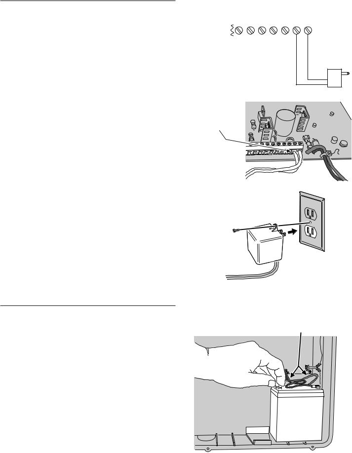
CONTROL PANEL POWER CONNECTION
The Control Panel is powered by a low voltage plug-in transformer.
Use up to 25 feet of 20 AWG or larger 2-conductor wire to connect the transformer to the Control Panel.
1.Route the power wires from the plug-in transformer to the Control Panel.
2.Connect the wires to the transformer terminals
(do not plug the transformer in until the wiring is complete).
3.Route the power wires through the Control Panel's wiring access slot or through a knockout for conduit wiring.
4.Connect the power wires from the transformer to the Control Panel's main terminal block AC & AC terminals.
5.Plug transformer into an unswitched AC outlet.
6.Secure transformer with screw to prevent unplugging.
BACKUP BATTERY INSTALLATION
A 12-volt backup battery may be installed and is highly recommended.
The backup battery will power the system for up to 6 hours during AC power loss.
The backup battery is automatically charged by the Control Panel when AC power is present.
A low backup battery will cause the keypad's POWER indicator to flash as it is being charged.
1.Position the battery as shown.
2.Connect the black battery lead to the negative battery terminal.
3.Connect the red battery lead to the positive battery terminal.
WARNING: DO NOT REVERSE THE BATTERY LEADS! THE BATTERY FUSE WILL BLOW.
MAIN TERMINAL BLOCK
|
KEYPAD |
|
|
|
XFRMR |
||||||
KPD |
KPD |
KPD |
KPD |
KPD |
AC |
AC |
|||||
- |
CLK |
DAT |
SPK + |
SPK- |
|||||||
|
|
|
|
|
|||||||
|
|
|
|
|
|
|
|
|
|
|
|
|
|
|
|
|
|
|
|
|
|
|
|
|
|
|
|
|
|
|
|
|
|
|
|
BE SURE TO SELECT AN
UN-SWITCHED AC OUTLET
FOR THE TRANSFORMER
CONNECT
TRANSFORMER WIRES
TO THE AC TERMINALS
ON THE MAIN TERMINAL
BLOCK
PLUG-IN TRANSFORMER
16 VAC, 28 VA
PLUG TRANSFORMER
INTO 115 VAC OUTLET
THAT IS NOT CONTROLED
BY A LIGHT SWITCH
SCREW
115 VAC OUTLET
TRANSFORMER
AFTER ALL WIRING IS COMPLETE, |
|
BE SURE RED WIRE ATTACHES |
|
TO POSITIVE (+) TERMINAL, AND |
|
CONNECT THE BACKUP BATTERY |
|
|
|
BLACK WIRE ATTACHES TO |
|
|
|
|
|
|
NEGATIVE (-) TERMINAL |
|
|
|
|
|
|
13
 Loading...