


AE-500
Telephone Entry
& Access Control
System
Installation Instructions
USA & Canada (800) 421-1587 & (800) 392-0123
(760) 438-7000 - Toll Free FAX (800) 468-1340
www.linearcorp.com

Contents
Introduction ........................................ |
2 |
Changing the Master Password.......... |
16 |
Operation............................................ |
2 |
Resident Data Programming .............. |
17 |
Hardware Features ............................. |
2 |
Entry Code Programming ................... |
18 |
Software Highlights ............................ |
2 |
Wireless Transmitter Programming .... |
19 |
Remote Keypads ................................. |
2 |
Wireless Transmitter Programming |
|
Feature Overview................................ |
3 |
(Continued)....................................... |
20 |
Component Locations ......................... |
4 |
System Options (Continued).............. |
21 |
Wiring Diagram................................... |
5 |
System Options (Continued).............. |
22 |
Important Mounting Requirements...... |
6 |
System Options (Continued).............. |
23 |
Entry System Mounting....................... |
7 |
System Utilities.................................. |
24 |
Entry System Mounting (Continued).... |
8 |
System Adjustments ......................... |
25 |
Relay Output Wiring ............................ |
9 |
System Diagnostics .......................... |
25 |
Power, Battery, & Ground Wiring ........ |
10 |
AE-500 Operation.............................. |
26 |
Optional Color CCTV Camera.............. |
10 |
Specifications ................................... |
27 |
Telephone Wiring ............................... |
11 |
Dimension Drawing........................... |
27 |
Optional Radio Antenna...................... |
11 |
Troubleshooting ................................ |
27 |
Optional Postal Lock .......................... |
12 |
Linear Limited Warranty.................... |
28 |
Optional Remote Keypad .................... |
12 |
FCC Notice........................................ |
28 |
Programming with a Computer .......... |
13 |
|
|
Programming Over the Telephone ...... |
14 |
|
|
Programming from the Local Keypad..14 |
|
|
|
Programming Reference..................... |
15 |
|
|
Factory Settings ................................ |
15 |
|
|
Programming Notes ........................... |
15 |
|
|
Setting Up Multiple Units ................... |
16 |
|
|
Introduction
The Model AE-500 Telephone Entry & Access Control System is designed for use as a primary access control device for gated communities, parking garages, offi ce buildings, apartments, dormitories, hotels/motels, commercial buildings and recreational facilities with up to 250 residents or users.
Housed in a locked, rugged stainless steel faced enclosure, the AE-500 features a side-lit 12-key telephone style keypad with bright, easy-to- read graphics, a backlit two-line directory display with a programmable welcome message, a built-in microphone, and speaker.
The two relay output channels can be programmed to control electric door strikes, magnetic locks, door & gate operators, or barrier gates. The system utilizes hands-free, full duplex telephone communications between visitors and residents for granting access.
The system can be programmed locally using the keypad, remotely with a touch tone telephone, or remotely using a computer equipped with a modem and a web browser.
Before starting the installation, read and understand these instructions. Become familiar with the illustrations and wiring diagrams. They will be a guide to installing the system in an effi cient and professional manner.
Operation
In a typical installation, the unit’s memory would be programmed with each resident’s name and directory code number. Arriving visitors would use the keypad on the AE-500 to view the directory names and directory number for the desired resident. Upon entering the directory number, the AE-500 will automatically dial the resident’s telephone number and establish two-way voice communication between the visitor and the resident. The resident will then have the option to grant or deny access to the visitor by pressing a digit on their telephone.
In addition to the telephone entry, the AE-500 can grant access using entry codes (up to 500 entry codes) at the local or remote keypad. Interior and exterior remote keypads are available.
Block coded and single enrolled MegaCode® transmitters (up to a total of 1000 transmitters) can be used to gain access through the AE-500’s built-in radio receiver. Each transmitter can be individually deactivated or reactivated. In addition, a single enrolled transmitter can be deleted.
Hardware Features
BUILT-IN RADIO RECEIVER
Variable gain, high-sensitivity receiver for wireless access media
TWO FORM “C” (N.O. & N.C) RELAYS
Each relay has 3-amp @ 30-volt rating
REQUEST-TO-EXIT INPUTS
Activates the access device for exiting using a hardwired switch
POSTAL SWITCH OPTION
Cabinet supports mounting a standard U.S.P.S. postal switch for mail carrier access
COLOR CAMERA OPTION
Cabinet supports mounting of a Linear color camera.
SENSING INPUT
For sensing door position to control door-ajar and alarm features, or for access inhibit timer
BUILT-IN ANNUNCIATOR
Programmable for beeps during output activations and chirps during keystrokes
BUILT-IN MODEM
No add-on modem required for telephone communications with system
MULTIPLE UNIT SUPPORT
Up to seven AE-500 units can be connected on the same telephone line
REMOTE KEYPAD SUPPORT
The system supports one Linear remote interior or exterior keypad
Software Highlights
LOCALLY PROGRAMMABLE
All programming can be performed from the local keypad
REMOTE TELEPHONE PROGRAMMING
All programming can be performed with a TouchTone™ telephone over the phone line
REMOTE COMPUTER PROGRAMMING
No dedicated programmer required, web-style programming with a computer and a modem
500 ENTRY CODES
Up to 500 entry codes can be used for gaining access
2-6 DIGIT ENTRY CODE LENGTH
Entry code lengths can be customized for small or large installations
250 RESIDENT DIRECTORY CAPACITY
Up to 250 residents can have directory numbers for telephone entry
2-4 DIGIT DIRECTORY NUMBER LENGTH
Directory Number lengths can be customized for small or large installations
500 TRANSMITTER CAPACITY
Up to 500 block coded Linear transmitters can be used for gaining access
TRANSMITTER FACILITY CODE SUPPORT
Identifies wireless access media by installation
TWO INDEPENDENT RELAY CHANNELS
Each output’s action is programmable
OBSTACLE TRANSMITTER SUPPORT
Compatible with Linear’s Model MGT transmitter
Remote Keypads
Two remote keypads are available to connect to the AE-500. One keypad can be used with each AE-500 unit.
|
|
|
AM-KP Exterior Keypad |
|
|
|
|
The Model AM-KP is housed in a rugged cast |
|
1 |
2 |
3 |
aluminum enclosure designed for exterior |
|
installations. The keypad can be mounted to a |
||||
4 |
5 |
6 |
||
7 |
8 |
9 |
pedestal or directly to a wall. A keylock secures the |
|
* |
0 |
# |
keypad to the mounting backplate. |
|
|
|
|
||
AM-KP |
|
|||
|
AM-KPI Interior Keypad |
|
The Model AM-KPI keypad is designed to be |
|
mounted indoors in a standard single-gang |
|
electrical box. Tamper resistant screws secure |
|
the keypad to its mounting plate. The die-cast |
|
keys are downlit with a white LED. The keypad |
|
is supplied with a satin-chrome bezel and three |
|
interchangeable colored bezels (white, ivory, & |
AM-KPI |
bronze) to customize the keypad appearance for |
the installation. |
2

Feature Overview
Relay Outputs
Two 3-amp dry contact relay outputs are provided to activate access devices, such as door strikes, magnetic locks, automatic doors, barrier gates, and automatic sliding gates. One relay output can also be used as a specialty output for alarm contact shunting, operator obstacle triggering, and alarm activation. LED indicators display the status of each relay.
Request-to-Exit Inputs
Both relay channels have request-to-exit inputs. These inputs are supplied for hardwire activation of the access devices. Typically a request-to-exit input is wired to a pushbutton inside of the access controlled area. When a person desires to exit, pressing the pushbutton will activate the output relay channel and trigger the access device. A loop detector for automatic gate operation can be connected to a request-to-exit input.
Sensing Input
The sensing input connects to a door switch that monitors whether the controlled door is open or closed. The sensing input may alternately be programmed as an “access inhibit” input for use with an external access timer or service switch.
Built-in Modem
A modular connector is provided for telephone line connection to the unit’s built-in 14.4K baud modem. The system can be accessed remotely for programming and control over the standard telephone system using a personal computer with a modem. For system backup, a computer connected through the modem can store and retrieve the AM-500’s memory data.
Local Keypad
The local keypad is the system’s primary keypad.
Remote Keypad
Two models of remote keypads (interior Linear AM-KPI and exterior Linear Model AM-KP) are compatible with the AE-500. A typical application for a remote keypad would be to control a second door or gate.
Postal Lock
The AE-500 cabinet has provisions for installing a U.S.P.S. postal lock for keyed mail carrier access. The postal lock will activate Relay Channel “A”.
Color Camera
The AE-500 cabinet has provisions for installing a Linear Model CCM-1 color camera for viewing the area in front of the cabinet.
Obstacle Detection
Linear’s Model MGT safety edge transmitter is compatible with the AE-500. The MGT detects and transmits obstacle events to the AE-500. Obstacle signals from a MGT transmitter will activate Relay Channel “B”.
Programming Memory
The AE-500’s EEPROM memory retains all entry codes, transmitter information, and programming, even without power.
Web-style Computer Programming
The system’s built-in, web-style programming interface can be accessed using a computer with any Internet browser on-site (using a separate phone line) or offsite. The intuitive graphic display of each of the programming step is the preferred method to program the AE-500.
Local Programming
All system programming options can be set from the AE-500’s keypad. A computer or dedicated programmer is not required to completely confi gure the AE-500.
Telephone Programming
System programming options can be set using a standard TouchTone™ telephone. By calling the AE-500 from a telephone, and entering the programming password, programming options can be changed and system functions can be controlled.
Battery Backup
The system supports a 12-volt battery backup for operation during power outage. The system does not charge the backup battery, an external battery charger is required to maintain the battery.
Database Overview
Programming the AE-500 involves entering installation information into the system’s memory. The system uses this information as a reference “database” to control the operation of the system.
Resident Data
Up to 250 resident names and telephone numbers can be set.Each resident entry is assigned a directory number. Directory numbers can be from two to four digits in length (all will be the same length).The directory number is the number a visitor would enter to have the system call the resident.
RESIDENT DATA (UP TO 250 RESIDENTS)
FOR EACH RESIDENT: DIRECTORY NUMBER (2 TO 4 DIGITS)
NAME (UP TO 16 CHARACTERS)
PHONE # (UP TO 12 DIGITS)
Entry Code Data
An entry code is a number entered at the AE-500 keypad or remote keypad to request access. Up to 500 entry codes can be set. Entry codes can be from two to six digits in length (all will be the same length).
Entry codes can be programmed for timed or toggle operation. Timed relays activate for a programmed length of time.Toggle relays latch on until the next time a toggle entry code is entered, then the relay unlatches. Each entry code can also be set for a limited or unlimited number of uses.
An entry code will activate Relay Channel “A” or “B” depending on how the entry code is programmed and whether or not a remote keypad is attached:
•When an entry code is programmed to activate a specifi c relay, the selected relay will activate when the code is entered on either the AE-500 keypad or the remote keypad.
•When an entry code is programmed to activate both relays, and a remote keypad is attached, Relay Channel “A” will activate if the entry code is entered on the AE-500 keypad; Relay Channel “B” will activate if the entry code is entered on the remote keypad.
•When an entry code is programmed to activate both relays, and a remote keypad is not attached, the entry code will activate both Relay Channels “A” and “B”.
When an entry code is programmed to activate both relays, only timed relay mode is available for that code, toggle relay mode is unavailable.
ENTRY CODE DATA (UP TO 500 CODES)
FOR EACH CODE: ENTRY CODE (2 TO 6 DIGITS)
RELAY SELECTOR
TEMPORARY USAGE COUNT
Transmitter Data
Up to 1000 wireless transmitters can be used with the system. Up to 500 transmitters can be ordered in pre-programmed blocks of sequential ID codes. Up to 16 blocks of transmitters can be used. Another option is to utilize up to 500 transmitters that are singly assigned. A transmitter will activate either relay output depending on the button programming (same for all transmitters in the system). An individual transmitter can be deactivated in case it is lost or stolen. A single enrolled transmitter can also be deleted.
TRANSMITTER DATA (UP TO 1000 TRANSMITTERS)
FOR EACH TRANSMITTER: TRANSMITTER ID # (1-65535)
OPTIONAL FACILITY CODE (0-15)
3

Component Locations
OPTIONAL
CAMERA
DISPLAY 
CABINET
LOCK
SPEAKER
KEYPAD
LIGHTING
RECEIVER
VIDEO OUT TEST POINTS
CONNECTOR
MICROPHONE
OPTIONAL
POSTAL
LOCK
KEYPAD
INSTALLATION NOTE:
FOR EASY WIRING, THE UNIT'S GREEN TERMINAL BLOCKS CAN BE UN-PLUGGED FROM THE CIRCUIT BOARD
|
|
RECEIVER |
MICROPHONE |
|
|
MAIN POWER |
RANGE KNOB |
CONNECTOR |
|
|
SWITCH |
ANTENNA |
|
|
|
CAMERA |
|
|
|
|
CONNECTOR |
|
DISPLAY |
|
EARTH |
POWER CONNECTOR |
MICROPHONE |
||
INDICATOR |
|
|
||
GROUND |
|
|
CAMERA |
|
|
|
|
||
STUD |
|
|
|
|
|
|
|
MOUNTING |
|
|
|
|
|
|
|
|
|
|
LOCATION |
POWER |
|
|
|
POSTAL LOCK |
TERMINALS |
|
|
|
|
|
|
|
MOUNTING PLATE |
|
KEYPAD |
|
|
|
|
|
|
|
POSTAL LOCK |
|
TERMINALS |
|
|
|
|
SPEAKER |
|
|
|
MICROSWITCH |
|
|
|
|
|
VOLUME |
|
|
|
TONE |
ADJUSTMENT |
|
|
|
|
|
|
|
VOLUME |
|
|
|
|
|
|
RELAY |
|
|
|
ADJUSTMENT |
|
|
|
|
|
TERMINALS |
|
|
|
|
INPUT |
|
|
|
SPEAKER |
|
|
|
|
|
TERMINALS |
|
|
|
|
TELEPHONE
TERMINALS
TELEPHONE
JACK
POSTAL SWITCH
CONNECTOR
SYSTEM
RESTART
BUTTON DISPLAY CONTRAST
ADJUSTMENT
JTAG
DISPLAY UPGRADE CONNECTOR CONNECTOR
KEYPAD
CONNECTOR
SPEAKER
CONNECTOR
KEYPAD
LIGHTING
CONNECTOR
4
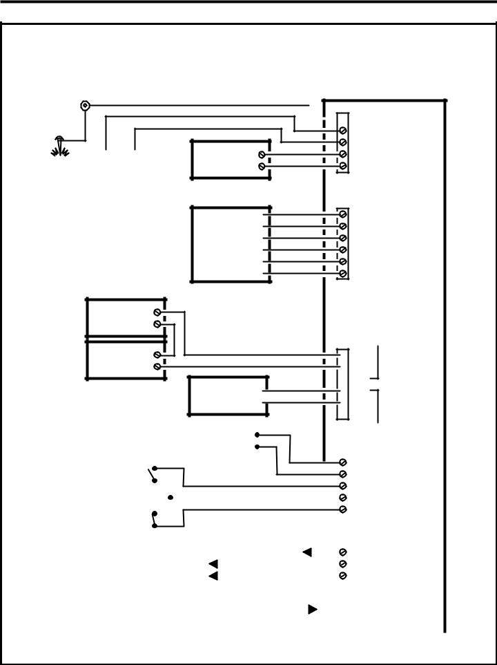
Wiring Diagram
THIS WIRING EXAMPLE SHOWS PRIMARY ACCESS WITH A DOOR STRIKE ON RELAY CHANNEL "A" AND SECONDARY ACCESS WITH A GATE OPERATOR ON RELAY CHANNEL "B"
CASE
GROUND
STUD
|
|
|
|
|
|
|
|
|
|
EARTH |
|
|
12 VOLT |
|
|||||
|
BATTERY |
|
|||||||
GROUND |
|
|
|||||||
STAKE NOTE: OPTIONAL |
|||||||||
|
BACKUP BATTERY |
||||||||
|
WILL REQUIRE AN |
||||||||
|
EXTERNAL CHARGER |
||||||||
REMOTE KEYPAD
FOR GATE ENTRY
16 VAC
20 VA
TRANSFORMER
PWR
GND
REMOTE DAT1 KEYPAD DAT0
 DVAL
DVAL PCLK
PCLK


 EARTH GROUND
DC + |
POWER |
DC - |
TERMINALS |
AC1 |
12-24 VOLTS |
AC2 |
AC/DC |
|
AE-500 |
PWR |
|
GND |
|
DAT1 |
KEYPAD |
DAT0 |
TERMINALS |
DVAL |
|
PCLK |
|
ELECTRIC
DOOR
STRIKE
DOOR
STRIKE
POWER SUPPLY
GATE
OPERATOR
OPEN

RELAY RATING:
3 AMPS @ 30 VOLTS AC/DC MAXIMUM
RELAY "A"

 N.O.
N.O.

 COM
COM
 N.C. RELAY

 N.O. TERMINALS

 COM
COM  N.C.
N.C.
|
|
|
|
|
|
|
DOOR EXIT |
|
|
|
|
|
|
|
|
|
|
|
|
|
|
|
|
|
|
|
RELAY "B" |
|||
|
|
|
|
|
|
|
|
|
|
|
|
|
|
|
|
|
|
|
||||||||||||
|
|
|
|
|
|
|
REQUEST |
|
|
|
|
|
|
|
|
|
|
|
|
|
|
|
|
|
|
|
|
|
|
|
|
|
|
|
|
|
|
|
|
|
|
|
|
|
|
|
|
|
|
|
|||||||||||
|
|
|
|
|
|
|
|
|
|
|
|
|
|
|
|
|
|
|
|
|
|
|
|
|
|
|
|
|
||
|
|
|
|
|
|
|
BUTTON |
|
|
|
|
|
|
|
|
|
|
|
|
|
|
|
|
|
RTE-A |
|
||||
GATE |
|
|
|
|
|
|
|
|
|
|
|
|
|
|
|
|
|
|
|
|
|
|
|
|
|
|
||||
|
|
|
|
|
|
|
|
|
|
|
|
|
|
|
|
|
|
|
|
|||||||||||
|
|
|
|
|
|
|
|
|
|
|
|
|
|
|
|
|
|
|
|
|
|
|
|
|||||||
EXIT LOOP |
|
|
|
|
|
|
|
|
|
|
|
|
|
|
|
|
|
|
GND |
INPUT |
||||||||||
|
|
|
|
|
|
|
|
|
|
|
||||||||||||||||||||
SENSOR |
|
|
|
|
|
|
|
|
|
|
|
|
|
|
|
|
|
RTE-B |
TERMINALS |
|||||||||||
|
|
|
|
|
|
|||||||||||||||||||||||||
|
|
|||||||||||||||||||||||||||||
|
|
|
|
|
|
|
|
|
|
|
|
|
|
|
|
|
|
|
|
|
|
|
|
|
|
|
|
GND |
|
|
|
|
|
|
|
|
|
|
|
|
|
|
|
|
|
|
|
|
|
|
|
|
|
|
|
|
|
|
|
||
DOOR |
|
|
|
|
|
|
|
|
|
|
|
|
|
|
|
|
|
|
|
|
DS-A |
|
||||||||
|
|
|
|
|
|
|
|
|||||||||||||||||||||||
|
|
|
|
|
|
|
|
|
|
|
|
|||||||||||||||||||
SENSE |
|
|
|
|
|
|
|
|
|
|
|
|
|
|
|
|
|
|
|
|
|
|||||||||
|
|
|
|
|
|
|
|
|
|
|
|
|
||||||||||||||||||
CONTACT |
|
|
|
|
|
|
|
|
|
|
|
|
|
|
|
|
|
|
EARTH GROUND |
|||||||||||
|
|
|
|
|
|
|
|
|
|
|||||||||||||||||||||
|
|
|
|
|
|
|
|
|
|
|
|
|
EARTH |
|
|
|
|
|
|
|
|
|||||||||
|
|
|
|
|
|
|
|
|
|
|
|
|
|
|
|
|
|
|
|
|
||||||||||
|
|
|
|
|
|
|
|
|
|
|
|
GROUND |
|
|
|
|
|
|
|
|
|
|
||||||||
|
|
|
|
|
|
|
|
|
|
|
|
|
|
|
|
|
||||||||||||||
|
|
|
|
|
|
|
|
|
|
|
|
|
|
|
|
|
|
|
|
|
|
|||||||||
TO DEDICATED |
|
|
|
|
|
|
|
|
|
|
|
|
|
TIP |
TELEPHONE |
|||||||||||||||
|
|
|
||||||||||||||||||||||||||||
|
|
|
|
|
|
|
|
|||||||||||||||||||||||
|
|
|
|
|
|
|
|
|
|
|
|
|
||||||||||||||||||
TELEPHONE LINE |
|
|
|
|
|
|
|
|
|
|
|
|
|
RING |
TERMINALS |
|||||||||||||||
|
|
|
|
|
|
|
|
|
||||||||||||||||||||||
|
|
|
|
|
|
|
|
|
|
|
|
|
||||||||||||||||||
|
|
|
|
|
|
|
|
|||||||||||||||||||||||
|
|
|
|
CONNECT TELEPHONE LINE TO |
|
|
|
|
|
|
|
|
|
|
|
|
|
|
|
|
TELEPHONE |
|||||||||
|
|
|
|
|
|
|
|
|
|
|
|
|
|
|
|
|
|
|
|
|||||||||||
|
|
|
|
|
|
|
|
|
|
|
|
|
|
|
|
|
JACK |
|||||||||||||
|
|
|
TERMINALS OR TELEPHONE JACK |
|
|
|
|
|
|
|
|
|
|
|||||||||||||||||
|
|
|
|
|
|
|
|
|
|
|
|
|
|
|||||||||||||||||
|
|
|
|
|
|
|
|
|
|
|
|
|
|
|
|
|
|
|
|
|
|
|
|
|
|
|
|
|
|
|
5
Important Mounting Requirements
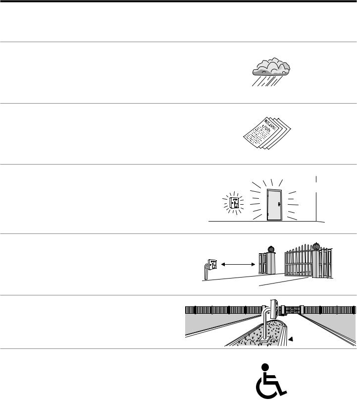
The AE-500 Telephone Entry System can be installed for public or private use. The mounting requirements will vary depending on the installation. Review the following information before beginning the installation.
Mounting Environment
Consider the environmental factors at the desired mounting location. The AE-500 is designed for direct outdoor installations, however, it is preferable to protect the unit from extreme exposure to sun, driving rain, or snow whenever possible. Mounting the unit in a kiosk can provide extra environmental protection.
Follow Building Codes
Check all local building codes and ordinances prior to installing the |
? |
|
system. Proper installation of the AE-500 conforming to the local building |
||
? |
||
codes for access control equipment is a regulatory requirement. The |
||
AE-500 installation is an extremely important and integral part of the |
? |
|
overall access control system. |
||
|
Mounting Location
If the AE-500 is used to control a door or pedestrian gate, locate the unit as near as practical to the entry point. If the unit is mounted on or in a wall adjacent to the entry point, be sure the wall is sturdy. The repeated shock and vibration from a slamming access door or spring-loaded pedestrian gate must be isolated from the AE-500. NEVER MOUNT THE UNIT
DIRECTLY TO A MOVING DOOR OR GATE!
Gate Installations
If the AE-500 is used to control a gate operator connected to a vehicular gate, the unit MUST be mounted AT LEAST 10 feet away from the gate (open and closed) and gate operator. AT NO TIME SHOULD A PERSON
BE ABLE TO TOUCH THE GATE OR GATE OPERATOR AND THE |
10 FEET |
MINIMUM |
|
AE-500 AT THE SAME TIME. |
|
Vehicle Traffic
Do not mount the AE-500 where it extends into any traffi c lane. Locate the gooseneck pedestal or entry kiosk so all parts of the AE-500 are outside the traffi c lane. Locate the AE-500 clear of any turn-around lanes vehicles use when access is denied.
Americans with Disability Act (A.D.A.) Requirements
THE FOLLOWING WHEELCHAIR ACCESS REQUIREMENTS ARE
FOR PUBLIC DOOR CONTROL INSTALLATIONS ONLY.
1.If the clear fl oor space allows only forward approach to the system, the maximum high forward reach allowed is 48” above grade to the top of the keypad.
2.If the high forward reach to the system is over an obstruction of greater than 20” but less than 25”, the maximum high forward reach allowed is 44” above grade to the top of the keypad.
3.If the clear fl oor space allows parallel approach by a person in a wheelchair, the maximum high side reach shall be 54” above grade to the top of the keypad.
4.If the high side reach is over an obstruction of 24” or less, the maximum high side reach allowed is 46” above grade to the top of the keypad.
?
?
?

 !
!
 EDGE OF TRAFFIC LANE
6

Entry System Mounting
The AE-500 cabinet is designed to be mounted three ways:
•The unit can be mounted directly to a wall or fl at surface.
•The unit can be mounted recessed into a wall.
•The unit can be mounted on a standard goose-neck pedestal. Choose a well lit location near the controlled opening. Wiring access for power, telephone, earth ground, and control output must be available to the mounting location. If the optional remote keypad or remote antenna it used, wiring access for these cables must also be available to the mounting location.
Static Electricity Warning
The unit’s main circuit board contains static sensitive electronic components that can be damaged or destroyed by static discharges during installation. Discharge the static electricity from your body by touching a grounded object before handling the unit’s circuit board.
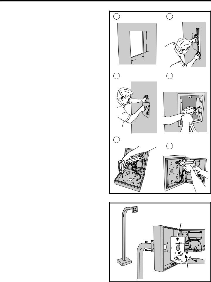
Mounting Preparation
Before mounting the system, the main circuit board must be removed to provide access for the wiring hole and mounting fasteners.
CAUTION!: Touch a grounded object before proceeding to discharge static electricity from your body.
1.Carefully remove the six main circuit board wiring harness connectors:
•The 2-pin postal switch connector.
•The 16-pin display connector.
•The 7-pin keypad connector.
•The 8-pin keypad lighting connector.
•The 3-pin speaker connector.
•The 2-pin microphone connector.
2.Remove the six circuit board screws. Note how the green ground wire lugs are connected with the upper left screw.
3.Carefully remove the circuit board. Hold it by the edges. Set it aside in a safe place.
Reverse these steps to replace the circuit board after the cabinet mounting is complete and the system wiring has been routed into the panel.
Surface Mounting
The cabinet can be mounted on a wall or any suitable fl at surface. The four 3/8” mounting holes or the four self-drill locations can be used to attach the cabinet to the surface.
1. For wall mounting, hold the cabinet at the approximate mounting location where the display will be about eye level or slightly above.
2A. If using the 3/8” mounting holes, mark the four mounting hole centers. Drill as required. Use the appropriate fasteners for the mounting surface to secure the cabinet.
2B. If using the self-drill mounting holes, choose the correct size bit for the fasteners and drill the cabinet as required. Use the appropriate fasteners for the mounting surface to secure the cabinet.
CAUTION!: After drilling, remove any metal chips from the inside of the cabinet.
3.After routing the wiring into the cabinet, replace the circuit board and plug in each wiring connector. Be sure to replace the green ground wire.
|
MOUNTING |
PREPARATION |
|
|
GROUND WIRE |
1 CAREFULLY REMOVE THE |
|
SIX WIRING HARNESS |
|
CONNECTORS |
|
2 |
REMOVE THE SIX |
|
CIRCUIT BOARD |
|
SCREWS |
3 CAREFULLY REMOVE THE |
|
CIRCUIT BOARD |
|
SURFACE |
|
MOUNTING |
|
1 MARK THE FOUR |
OR |
MOUNTING HOLES |
DRILL THE CABINET AT THE
PRE-MARKED LOCATIONS
2ATTACH THE CABINET WITH APPROPRIATE HARDWARE FOR THE MOUNTING SURFACE
7
Entry System Mounting (Continued)
Recessed Mounting
The cabinet can be mounted recessed using the accessory trim-ring (P/N ACP00908). The trim-ring mounts in the wall and the cabinet attaches to the trim-ring.
1.Identify the location of any studs in the wall.
2.Cut a 13” high by 11” wide rectangular hole between studs at the mounting location.
3.Install any additional mounting material required to provide surfaces inside the wall 11” apart for attaching the trim-ring.
4.Place the trim-ring in the wall hole. Check for level, then attach the trim-ring with up to six screws into the side tabs.
5.Drill 3/16” holes in the cabinet’s six pre-marked locations.
CAUTION!: After drilling, remove any metal chips from the inside of the cabinet.
6.Route the wiring through the trim-ring and into the cabinet through the center wiring hole.
7.Attach the cabinet to the trim-ring using self-tapping screws supplied.
8.Replace the circuit board and plug in each wiring connector. Be sure to replace the green ground wires.
1 DETERMINE LOCATION FOR |
2 MARK HOLE LOCATION |
THE 11" x 13" MOUNTING HOLE |
|
|
RECESSED |
|
MOUNTING |
13" |
|
11" |
|
3 CUT MOUNTING HOLE |
4 INSTALL ANY SHIMS TO |
|
ALLOW MOUNTING AND |
|
ATTACH THE TRIM-RING |
|
WITH UP TO 6 SCREWS |
5 |
DRILL 3/16" HOLES IN |
|
|
THE CABINET AT THE |
|
ATTACH THE CABINET TO |
|
|
PRE-MARKED LOCATIONS |
6 |
|
|
|
THE TRIM-RING WITH |
|
|
|
|
SELF-TAPING SCREWS |
Pedestal Mounting
The cabinet can be mounted on a standard goose-neck pedestal. When mounting to a pedestal, use the cabinet reinforcing plate to stiffen the cabinet.
1.Install the pedestal at the desired location.
2.Place the reinforcing plate inside the cabinet.
3.Use security hardware to attach the cabinet and reinforcing plate to the pedestal.
4.After routing the wiring into the cabinet, replace the circuit board and plug in each wiring connector. Be sure to replace the green ground wires.
PEDESTAL
MOUNTING
ALIGN THE REINFORCING PLATE
ON THE INSIDE OF THE CABINET
PEDESTAL
USE SECURITY HARDWARE
TO ATTACH THE PLATE AND
CABINET TO THE PEDESTAL
8
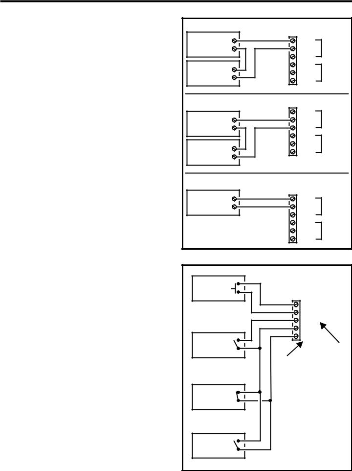
Relay Output Wiring
Either or both of the two relay output channels (A or B) can be used to control door or gate access. Relay Channel “B” can be used for alarm control functions.
Door or Pedestrian Gate Control
1.Install a low voltage electric door strike or magnetic lock as a locking device for the door or pedestrian gate.
2.Install the power supply or transformer for the locking device. DO
NOT POWER THE AE-500 FROM THIS POWER SUPPLY.
3.Connect one wire from the power supply to one wire from the locking device.
4.Route two wires between the locking device and the AE-500. Connect one wire to the remaining wire of the locking device. Connect the other wire to the remaining wire of the power supply.
5A. For a door strike, connect the wires to the AE-500 relay COM & N.O. terminals.
5B. For a magnetic lock, connect the wires to the AE-500 relay COM & N.C. terminals.
Gate Control
1.Route two wires between the gate and the AE-500.
2.Connect the gate operator’s OPEN terminals to the AE-500 relay COM & N.O. terminals.
NOTE: For operator wiring specifics, refer to the gate operator’s wiring diagram.
Request-to-Exit Inputs
Each relay output has a request-to-exit input terminal. Grounding this terminal will activate the associated relay. These inputs are typically used with push bars, loop sensors, or pushbuttons.
1.Install the pushbutton or device to signal an exit request.
2.Route two wires from the device to the AE-500.
3.Connect the device’s normally open output to the wires.
4A. To activate Relay Channel “A”, connect the wires to the RTE-A and GND terminals.
4B. To activate Relay Channel “B”, connect the wires to the RTE-B and GND terminals.
Sensing Input
The sensing input connects to a door switch that monitors whether the controlled door is open or closed. The sensing input may alternately be programmed as an “access inhibit” input for use with an external access timer or service switch to prevent access from being granted with Relay Channel “A”.
1A. To use the door sense feature to detect forced entry or door ajar conditions, install a normally closed door switch on the door or pedestrian gate and route two wires from the switch to the AE-500.
1B. To use the sensing input as an access inhibit input, install an external timer or service switch with a normally open output and route two wires from it to the AE-500.
2. Connect the sensing device wires to the DS-A and GND terminals.
NOTE: To program the sensing input as access inhibit, refer to the Sensing Input Function (PPN #54) step in the System Options section of these instructions.
TYPICAL DOOR STRIKE HOOKUP |
|
||
ELECTRIC |
N.O. |
|
|
DOOR |
|
||
COM |
RELAY "A" |
||
STRIKE |
|||
N.C. |
|
||
|
|
||
DOOR |
N.O. |
|
|
STRIKE |
COM |
RELAY "B" |
|
POWER SUPPLY |
N.C. |
|
|
TYPICAL MAGNETIC LOCK HOOKUP |
|
||
MAGNETIC |
N.O. |
|
|
COM |
RELAY "A" |
||
DOOR |
|||
N.C. |
|
||
LOCK |
|
||
N.O. |
|
||
|
|
||
DOOR |
COM |
RELAY "B" |
|
LOCK |
N.C. |
|
|
POWER SUPPLY |
|
|
|
TYPICAL AUTOMATIC GATE HOOKUP |
|
||
OPERATOR OPEN |
COM |
RELAY "A" |
|
GATE |
N.O. |
|
|
|
N.C. |
|
|
RELAY RATING: |
N.O. |
|
|
3 AMPS @ 30 VOLTS |
COM |
RELAY "B" |
|
AC/DC MAXIMUM |
N.C. |
|
|
DOOR EXIT |
|
INPUT |
REQUEST |
|
|
|
TERMINALS |
|
BUTTON |
|
|
|
|
|
|
|
RTE-A |
|
|
GND |
|
|
RTE-B |
|
|
GND |
GATE |
|
DS-A |
EXIT LOOP |
|
RTE |
SENSOR |
|
|
|
REQUEST-TO-EXIT |
|
|
DS-A |
|
|
TERMINALS |
|
|
|
|
|
SENSING |
|
|
INPUT TERMINAL |
|
DOOR |
NOTE: DOOR |
|
SENSE |
SENSE CONTACT |
|
CONTACT |
IS NORMALLY CLOSED |
|
- OR - |
|
|
ACCESS |
NOTE: ACCESS INHIBIT |
|
INHIBIT |
TIMER SWITCH |
|
TIMER |
IS NORMALLY OPEN |
|
|
|
9 |
 Loading...