


AE-2000
Telephone Entry
& Access Control
System
Installation Instructions
USA & Canada (800) 421-1587 & (800) 392-0123
(760) 438-7000 - Toll Free FAX (800) 468-1340
www.linearcorp.com

Contents |
|
Introduction ........................................................................... |
2 |
Operation............................................................................... |
2 |
Hardware Features ................................................................ |
3 |
Software Highlights ............................................................... |
3 |
Feature Overview................................................................... |
3 |
Accessory Overview............................................................... |
4 |
PBUS Accessories.................................................................. |
4 |
Wiegand Accessories ............................................................. |
4 |
Component Locations ............................................................ |
5 |
Wiring Diagram...................................................................... |
6 |
Important Mounting Requirements......................................... |
7 |
Entry System Mounting.......................................................... |
8 |
Entry System Mounting (Continued)....................................... |
9 |
Relay Output Wiring .............................................................. |
10 |
Power, Battery, & Ground Wiring ........................................... |
11 |
RS-232 Port .......................................................................... |
11 |
Telephone Wiring .................................................................. |
12 |
Optional Radio Antenna......................................................... |
12 |
Optional Postal Lock ............................................................. |
13 |
Optional Color CCTV Camera ................................................ |
13 |
PBUS Accessories................................................................. |
14 |
Wiegand Accessories ............................................................ |
14 |
Optional Network Connection................................................ |
15 |
System Adjustments ............................................................. |
16 |
System Diagnostics .............................................................. |
16 |
Internal Controls ................................................................... |
17 |
AE-2000 Operation................................................................ |
18 |
Specifications ....................................................................... |
19 |
Dimension Drawing............................................................... |
19 |
Troubleshooting ................................................................... |
20 |
Linear Limited Warranty....................................................... |
20 |
FCC Notice........................................................................... |
20 |
Introduction
The Model AE-2000 Telephone Entry & Access Control System is designed for use as a primary access control device for gated communities, parking garages, offi ce buildings, apartments, dormitories, hotels/motels, commercial buildings and recreational facilities.
Housed in a locked, rugged stainless steel faced enclosure, the AE2000 features a lighted keypad with bright, easy-to-read graphics, a large backlit display with programmable welcome message, a built-in microphone, speaker, and provision for an optional color CCTV camera. The cabinet is monitored with a magnetic “tamper” switch.
The four relay output channels can be programmed to control electric door strikes, magnetic locks, door & gate operators, or barrier gates. The system utilizes hands-free, full duplex telephone communications between visitors and residents for granting access. Complete access control event logging, access time restriction, access location restriction, and administration functions are also available to manage the installation.
The AE-2000 is network ready. Multiple units can be interconnected on a 3-wire RS-485 network.
Two Wiegand inputs are available for connection of 26, 30, or 31-bit Wiegand devices (card readers, etc.). Three sets of PBUS inputs are available for connection to Linear’s line of remote accessories.
Operation
In a typical installation, the unit’s memory would be programmed with each resident’s name and directory code number. Arriving visitors would use the keys on the AE-2000 to view the directory names and directory number for the desired resident. Upon selecting the directory number, the AE-2000 will automatically dial the resident’s telephone number and establish two-way voice communication between the visitor and the resident. The resident will then have the option to grant or deny access to the visitor by pressing a digit on their telephone.
In addition to the telephone entry, the AE-2000 can grant access using entry codes at the local or remote keypads. Also remote receivers, card readers, and interior and exterior keypads can be used with the system. Block coded MegaCode® transmitters can be used to gain access through the AE-2000’s built-in or remote radio receivers. Each transmitter can be individually suspended or re-activated.
The system’s clock/calendar can control access based on specifi c times and dates. Automatic relay activation can be scheduled. Access can be restricted to certain times and dates. Holiday access can be scheduled. The system’s event log records system activity for future reference.
2

Hardware Features
BUILT-IN RADIO RECEIVER
Variable gain, high-sensitivity receiver for wireless transmitters
FOUR FORM “C” (N.O. & N.C) RELAYS
Each relay has 3-amp @ 24-volt rating
FOUR REQUEST-TO-EXIT INPUTS
Activates access device for exiting using a hardwired switch
FOUR SENSING INPUTS
For sensing door position to control door-ajar and alarm features
BUILT-IN ANNUNCIATOR
Chirps during keystrokes
BUILT-IN MODEM
No add-on modem required for telephone communications with system
RS-232 PORT
COM port for direct connection to a computer
NETWORK SUPPORT
Multiple units can be connected together to share data
EXPANSION INTERFACE SUPPORT
Model AM-MIO accessory adds additional input and outputs to the AE-2000
ON-BOARD CLOCK/CALENDAR CIRCUIT
Stamps the event log data as it is stored in the system’s memory
WIEGAND INPUTS
Two Wiegand format card reader inputs for connection to external devices.
LINEAR PBUS SUPPORT
Three PBUS input/output ports for connection of up to 6 Linear accessories.
CCTV COLOR CAMERA SUPPORT
Model CCM-1 accessory camera allows color video monitoring of the keypad area
POWER FAILURE MONITOR
AC power input is monitored, power outages are recorded in the event log
Software Highlights
COMPUTER PROGRAMMABLE
No dedicated programmer required, program with a computer and a modem
LARGE ENTRY CODE CAPACITY
Up to 20,000 entry codes can be used for gaining access
2-8 DIGIT ENTRY CODE LENGTH
Flexible code length for different applications
LARGE RESIDENT DIRECTORY CAPACITY
Up to 10,000 residents
2-4 DIGIT DIRECTORY NUMBER LENGTH
Directory number lengths can be customized for small or large installations
LARGE TRANSMITTER CAPACITY
Up to 45,600 block coded and 20,000 individually enrolled Linear transmitters can be used for gaining access
TRANSMITTER FACILITY CODE SUPPORT
Identifies wireless transmitters by installation
LARGE CARD CAPACITY
Up to 45,600 block coded and 20,000 individually enrolled cards can be used for gaining access
FOUR INDEPENDENT RELAY CHANNELS
Each output’s action is programmable
PROGRAMMABLE TIME SCHEDULED RELAY ACTIVATION
Activation for up to four time periods for each of the 31 system time zones
PROGRAMMABLE TIME ZONE ACCESS VALIDATION
Validation during four time periods for each of the 31 system time zones
PROGRAMMABLE VALIDATION DAYS
Select days of the week access is allowed
PROGRAMMABLE HOLIDAY DAYS
Select up to 24 expiring & 24 non-expiring holidays for access restriction
OBSTACLE TRANSMITTER SUPPORT
Compatible with Linear’s Model MGT transmitter
EVENT LOG
Stores up to 20,000 system events in memory for record keeping
DELETED CARDHOLDER DATABASE
System logs deleted cardholders for future identification
TIMED ANTI-PASSBACK
Disables entry code for a programmed time after use
Feature Overview
Relay Outputs
Four 3-amp dry contact relay outputs are provided to activate access devices, such as door strikes, magnetic locks, automatic doors, barrier gates, and automatic sliding gates. The relay outputs can also be used as specialty outputs for alarm contact shunting, operator obstacle triggering, and alarm activation. Each of the relays can also be manually activated from buttons on the AE-2000 circuit board. LED indicators display the status of each relay.
Request-to-Exit Inputs
Each relay channel has a request-to-exit input. These inputs are supplied for hardwire activation of the access devices. Typically a request-to-exit input is wired to a pushbutton inside of the access controlled area. When a person desires to exit, pressing the pushbutton will activate the output relay channel and trigger the access device. A loop detector for automatic gate operation can be connected to a request-to-exit input.
Sensing Inputs
The sensing inputs connect to door switches that monitor whether the controlled door is open or closed.
Built-in Modem
A modular connector is provided for telephone line connection to the unit’s built-in 33.6K baud modem. The system can be accessed remotely for programming and control over the standard telephone system using a personal computer with a modem. For system backup, a computer connected through the modem can store and retrieve the AE-2000’s memory data.
RS-232 Communications Port
A modular connector is provided for the bi-directional 38.4K baud RS-232 port. The AE-2000’s RS-232 port connects to a personal computer’s COM port. System programming can be performed locally with a computer connected to the RS-232 port.
Local Keypad
The local keypad is the system’s primary keypad. The local keypad activates Relay Channel “A”, but can be programmed for any of the relays.
Postal Lock
The AE-2000 cabinet has provisions for installing a U.S.P.S. postal lock for keyed mail carrier access. The postal lock will activate Relay Channel “A”, but can be programmed for any of the relays.
Obstacle Detection
Linear’s Model MGT safety edge transmitter is compatible with the AE-2000. The MGT detects and transmits obstacle events to the AE-2000.
Programming Memory
The AE-2000’s fl ash memory retains all entry codes, transmitter information, card access, and programming, even without power.
Computer Programming
The system programming can be accomplished by a computer and modem using Linear’s AccessBase2000 programming software.
Battery Backup
The system supports a 12-volt battery backup or uninterruptable power supply for operation during power outage. The system does not charge the backup battery, an external battery charger is required to maintain the battery.
Network Support
Multiple AE-1000, AE-2000, & AM-3 units can be networked together via RS-485 allowing information sharing between the units. Networked units are interconnected with a three-wire cable. A common event log is retained for all of the networked units.
Linear PBUS Ports
Three 6-wire Linear PBUS input/output ports are available to connect to several accessories (keypads, proximity readers, remote receivers). A typical application for a remote keypad or reader would be to control additional doors or gates.
3
Accessory Overview |
|
|
PBUS Accessories |
||||
|
|
|
Several compatible accessories are available to connect to the AE-2000’s |
||||
|
|
|
three 6-wire communications “PBUS” inputs. Up to six PBUS accessories |
||||
|
|
|
can be used with each AE-2000 unit. |
||||
|
|
|
|
|
|
AM-RRR Remote Radio Receiver |
|
|
|
|
|
|
|
For wireless transmitters, connect the Model AM- |
|
|
|
|
|
|
|
RRR high-gain superheterodyne UHF receiver. The |
|
|
|
EXA-2000 |
|
|
|
receiver is housed in a weather-resistant enclosure |
|
|
|
|
|
|
and can be mounted indoors or outdoors. Gaskets |
||
|
|
REMOTE |
|
|
|
||
AM-RRR |
|
RADIO |
|
|
|
and a weather-tight wiring strain relief seal the unit |
|
|
ANTENNA |
|
|
|
from the elements. |
||
REMOTE |
|
|
AM-RRR |
|
AM-RPR Radio Proximity Receiver |
||
RADIO |
|
|
|
||||
|
|
|
|
|
|||
RECEIVER |
|
|
|
|
|
The Model AM-RPR functions as a remote device |
|
|
|
|
|
|
|
that supplies localized radio reception for the |
|
|
|
|
|
|
|
AE-2000 In a typical installation, the AM-RPR |
|
AE-2000 |
|
|
|
|
|
would be mounted in a plastic single-gang electrical |
|
|
|
|
|
|
box next to the controlled opening. When the user |
||
TELEPHONE ENTRY |
|
|
|
|
requires access, their transmitter must be activated |
||
& ACCESS CONTROL |
|
|
|
|
|||
|
|
|
|
within three inches of the AM-RPR faceplate. |
|||
SYSTEM |
|
|
|
|
|
||
|
|
AM-RPR |
AM-KP Exterior Keypad |
||||
|
|
|
|||||
|
|
|
|
|
|
The Model AM-KP is housed in a rugged cast |
|
|
|
|
|
|
|
aluminum enclosure designed for exterior |
|
|
|
|
|
|
|
installations. The die-cast keys have bright, |
|
|
|
|
1 |
2 |
3 |
easy-to-read yellow graphics. The keypad can |
|
|
|
|
4 |
5 |
6 |
be mounted to a pedestal or directly to a wall. |
|
|
|
|
7 |
8 |
9 |
||
|
|
|
* |
0 |
# |
A keylock secures the keypad to the mounting |
|
|
|
|
AM-KP |
backplate. |
|||
|
|
|
|
|
|
AM-KPI Interior Keypad |
|
|
|
|
|
|
|
The Model AM-KPI keypad is housed in a rugged, |
|
|
|
|
|
|
|
plastic enclosure designed to be mounted indoors |
|
|
|
|
|
|
|
in a standard single-gang electrical box. Tamper |
|
|
|
|
|
|
|
resistant screws secure the keypad to its mounting |
|
|
|
|
|
|
|
plate. The die-cast keys have bright, easy-to-read |
|
|
|
WIEGAND |
|
|
|
yellow graphics and is illuminated with white |
|
|
|
|
|
|
LEDs.The keypad is supplied with a satin-chrome |
||
|
ACCESSORIES |
|
|
|
|||
PBUS |
AM-KPI |
bezel and three interchangeable colored bezels |
|||||
|
|
||||||
ACCESSORIES |
|
|
|
|
|
(white, ivory, & bronze) to customize the keypad |
|
|
|
|
|
|
|
appearance for the installation. |
|
|
|
|
|
|
|
AM-CRI Card Reader Interface |
|
|
|
|
|
|
|
The Model AM-CRI expands the standard two |
|
|
|
|
|
|
|
AE-2000 Wiegand inputs by supporting one or |
|
AM-KPI |
|
|
|
|
|
two additional 26-bit Wiegand input devices per |
|
AM-WOR |
|
|
|
AM-CRI |
AM-CRI interfaces used. |
||
INTERIOR |
|
|
|
||||
WIEGAND |
|
|
|
|
|
||
KEYPAD |
|
Wiegand Accessories |
|||||
OUTPUT |
|
||||||
|
|
||||||
|
RECEIVER |
Two Linear accessories are available to connect WIEGAND format |
|||||
|
|
|
|||||
|
|
|
devices to the AE-2000. Most other manufacturer’s 26, 30 & 31-bit |
||||
|
|
|
WIEGAND output devices can also be used with the AE-2000. |
||||
|
AM-PR |
|
|
|
|
WOR Wiegand Output Radio Receiver |
|
|
PROXIMITY |
|
|
|
|
For block-coded Linear wireless transmitters, |
|
|
READER |
|
|
|
|
||
|
|
|
|
|
connect the Model WOR high-gain superheterodyne |
||
* |
|
|
|
|
|
||
|
|
|
|
|
UHF receiver. The receiver is housed in a weather- |
||
AM-KP |
|
|
|
|
|
||
|
|
|
|
|
resistant enclosure and can be mounted indoors or |
||
EXTERIOR |
|
|
|
|
|
||
|
|
|
|
|
outdoors. Gaskets and a weather-tight wiring strain |
||
KEYPAD |
|
|
|
|
|
||
|
|
|
|
|
|
relief seal the unit from the elements. |
|
|
|
|
|
|
WOR |
AM-PR Proximity Reader |
|
|
|
|
|
|
|
The Model AM-PR is a radio-based reader that |
|
|
|
|
|
|
|
works with either proximity tags (Model AM-PT) |
|
AM-RPR |
AM-CRI |
|
|
|
|
or proximity cards (Model AM-PC), both of which |
|
|
|
|
|
are slotted to attach to key rings. Upon reading a |
|||
RADIO |
|
|
|
|
|||
CARD |
|
|
|
|
|||
|
|
|
|
user’s tag or card, it transmits the entry data via a |
|||
PROXIMITY |
|
|
|
|
|||
READER |
|
|
|
|
|||
RECEIVER |
|
|
|
|
Wiegand output to the AE-2000. An integral LED |
||
INTERFACE |
|
|
|
|
|||
|
|
|
|
|
AM-PR |
confi rms to the user that access is granted. |
|
4 |
|
|
|
|
|
|
|

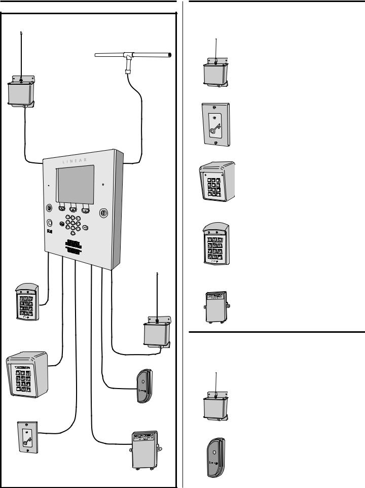
Component Locations
|
DISPLAY |
|
|
|
|
|
|
MICROPHONE |
|
|
OPTIONAL |
||
|
|
|
CAMERA |
|
||
|
|
|
|
|
||
|
LEFT |
|
|
FUNCTION |
|
|
|
CABINET |
|
|
|
||
|
|
|
BUTTONS |
|
||
|
LOCK |
|
|
|
||
|
|
|
|
|
||
|
OPTIONAL |
|
|
RIGHT |
|
|
|
POSTAL |
|
|
CABINET |
|
|
|
LOCK |
|
|
LOCK |
|
|
|
SPEAKER |
|
|
KEYPAD |
|
|
|
|
|
|
|
||
|
INSTALLATION NOTE: |
|
|
|
|
|
FOR EASY WIRING, THE UNIT'S TERMINAL BLOCKS |
|
|
|
|||
CAN BE UN-PLUGGED FROM THE CIRCUIT BOARD |
|
|
|
|||
|
|
|
|
PROMPT SPEECH |
|
|
TAMPER |
CPU/INTERFACE |
ANTENNA |
|
VOLUME |
RESIDENT'S VOICE |
|
CONNECTOR TAMPER |
ADJUSTMENT |
|||||
SWITCH |
CONNECTOR |
VOLUME |
||||
OPTIONAL |
||||||
|
RECEIVER |
SWITCH |
ADJUSTMENT |
|||
CAMERA |
RANGE KNOB |
CONNECTOR |
CAMERA |
TAMPER |
||
|
|
|
|
|||
CONNECTOR |
|
|
|
|
||
|
|
|
|
MAGNET |
||
(HIDDEN) |
|
|
|
|
||
|
|
|
|
|
||
VIDEO |
|
|
|
|
|
|
CONNECTOR |
|
|
|
|
|
|
WIEGAND |
INPUT |
TERMINALS |
PBUS |
TERMINALS |
NETWORK |
|
|
|
|
|
TERMINALS |
|
|
|
|
|
AM-MIO |
|
|
|
|
|
INTERFACE |
|
|
|
|
|
TELEPHONE |
|
|
|
|
|
INTERFACE |
|
RS-232 |
POWER |
|
|
CONNECTOR |
TELEPHONE PORT |
TERMINALS |
EARTH |
KEYPAD |
|
TELEPHONE |
JACK |
MAIN POWER |
GROUND |
POWER |
|
TERMINALS |
|
SWITCH |
STUD |
CONNECTOR |
|
MICROPHONE
SYSTEM
RESTART
BUTTON
RELAY
TERMINALS
POSTAL LOCK
MOUNTING
PLATE
SPEAKER
PROCESSOR MODULE
POWER CONNECTOR
5
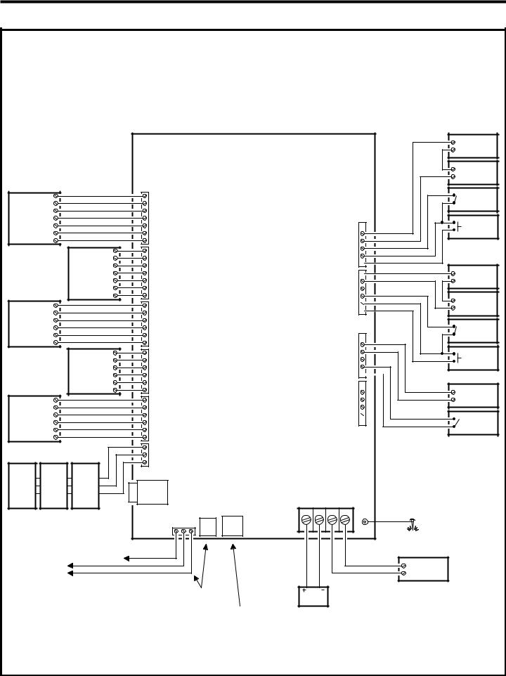
Wiring Diagram
THIS WIRING EXAMPLE SHOWS:
DOOR ACCESS WITH A DOOR STRIKE ON RELAY CHANNEL "A" DOOR ACCESS WITH A MAGNETIC LOCK ON RELAY CHANNEL "B" GATE ACCESS WITH A GATE OPERATOR ON RELAY CHANNEL "C" (YOUR INSTALLATION MAY VARY)
|
|
|
|
|
|
|
|
AE-2000 |
|
LED2 |
|
|
LED2 |
|
|
|
|
|
HOLD |
|
|
HOLD |
|
|
|
|
WIEGAND |
LED1 |
|
|
LED1 |
READER A |
|
|
|
DAT 1 |
|
|
DAT 1 |
|
|
|||
DEVICE |
DAT 0 |
|
|
DAT 0 |
TERMINALS |
|
|
|
|
|
|
|
|
|
|
||
|
GND |
|
|
GND |
|
|
|
|
|
PWR |
|
|
PWR |
|
|
|
|
|
|
|
LED2 |
LED2 |
|
|
|
|
|
|
|
HOLD |
HOLD |
|
|
|
|
|
|
WIEGAND |
LED1 |
LED1 |
READER B |
|
|
|
|
|
DAT 1 |
DAT 1 |
|
|
|||
|
|
DEVICE |
DAT 0 |
DAT 0 |
TERMINALS |
|
|
|
|
|
|
|
|
|
|
||
|
|
|
GND |
GND |
|
|
|
|
|
|
|
PWR |
PWR |
|
|
|
|
|
PWR |
|
|
PWR |
|
|
|
|
|
GND |
|
|
GND |
|
|
|
|
PBUS |
DAT1 |
|
|
DAT1 |
PBUS "A" |
|
|
|
DEVICE |
DAT0 |
|
|
DAT0 |
TERMINALS |
|
|
|
|
DVAL |
|
|
DVAL |
|
|
|
|
|
PCLK |
|
|
PCLK |
|
|
|
|
|
|
|
PWR |
PWR |
|
|
|
|
|
|
|
GND |
GND |
PBUS "B" |
|
|
|
|
|
PBUS |
DAT1 |
DAT1 |
|
|
||
|
|
DEVICE |
DAT0 |
DAT0 |
TERMINALS |
|
|
|
|
|
|
DVAL |
DVAL |
|
|
|
|
|
|
|
PCLK |
PCLK |
|
|
|
|
|
PWR |
|
|
PWR |
|
|
|
|
|
GND |
|
|
GND |
|
|
|
|
PBUS |
DAT1 |
|
|
DAT1 |
PBUS "C" |
|
|
|
DEVICE |
DAT0 |
|
|
DAT0 |
TERMINALS |
|
|
|
|
DVAL |
|
|
DVAL |
|
|
|
|
|
PCLK |
|
|
PCLK |
|
|
|
|
|
|
|
|
NET-B |
NETWORK |
|
|
|
|
|
|
|
GND |
|
|
||
|
|
|
|
TERMINALS |
|
|
||
|
|
|
|
NET-A |
|
|
||
|
|
|
|
|
|
|
|
|
AE-1000 |
AE-1000 |
AE-1000 |
|
|
|
|
|
|
AE-2000 |
AE-2000 |
AE-2000 |
|
AM-MIO |
|
|
|
|
AM-3 |
AM-3 |
AM-3 |
|
|
|
|
|
|
|
INTERFACE |
GND |
|
|
|
|||
|
|
|
|
|
|
RS-232 |
||
|
|
|
|
|
TELEPHONE |
|||
MULTIPLE NETWORK UNITS |
|
|
EARTH |
TIP RING |
JACK |
PORT |
||
|
|
|
||||||
|
|
|
|
|||||
REFER TO NETWORK SECTION |
|
TELEPHONE |
|
|
||||
FOR WIRING OPTIONS |
|
|
|
|
|
|||
|
TERMINALS |
|
|
|
|
|||
|
|
|
|
|
|
|
|
|
|
|
|
EARTH |
|
|
|
|
|
|
|
|
GROUND |
|
|
|
|
|
TO DEDICATED |
|
|
|
|
|
|
|
|
TELEPHONE LINE |
|
|
|
|
|
|
|
|
CONNECT TELEPHONE LINE TO
TERMINALS OR TELEPHONE JACK
FOR LOCAL COMPUTER CONNECTION
USE LINEAR MODEL A2C
SERIAL COMPUTER CABLE
N.C. 
RELAY
COM
CHANNEL "A"
N.O.
DS-A
TERMINALS GND
RTE-A 
N.C. 
RELAY
COM
N.O.
CHANNEL "B" DS-B
TERMINALS GND 
RTE-B 
RELAY RATING: 3 AMPS @ 30 VOLTS
AC/DC MAXIMUM
N.C. 
RELAY
COM
CHANNEL "C"
N.O.
DS-C
TERMINALS GND
RTE-C 
N.C. 
RELAY
COM
N.O.
CHANNEL "D" DS-D
TERMINALS GND 
RTE-D 
POWER |
|
|
TERMINALS |
|
|
12-24 VOLTS AC/DC |
|
|
DC + DC - AC |
AC |
GROUND |
|
|
|
|
|
STUD |
EARTH
GROUND
STAKE
ELECTRIC
DOOR
STRIKE
DOOR
STRIKE
POWER SUPPLY
DOOR
SENSE
CONTACT
DOOR EXIT
REQUEST
BUTTON
MAGNETIC
DOOR
LOCK
DOOR
LOCK
POWER SUPPLY
DOOR
SENSE
CONTACT
DOOR EXIT
REQUEST
BUTTON
OPEN |
OPERATOR |
|
GATE |
GATE
EXIT LOOP
SENSOR
16 VAC
20 VA
TRANSFORMER
12 VOLT BATTERY
NOTE: OPTIONAL
BACKUP BATTERY
WILL REQUIRE AN
EXTERNAL CHARGER
6
 Loading...