


RETURN TO MAIN MENU
IM533
IDEALARC SP-255 |
June, 1998 |
|
|
|
|
For use with machine Code Numbers 10164, 10165 |
|
Safety Depends on You
Lincoln arc welding and cutting equipment is designed and built with safety in mind. However, your overall safety can be increased by proper installation ... and thoughtful operation on your part. DO NOT INSTALL, OPERATE OR REPAIR THIS EQUIPMENT WITHOUT READING THIS MANUAL AND THE SAFETY PRECAUTIONS CONTAINED THROUGHOUT. And, most importantly, think before you act and be careful.
OPERATOR’S MANUAL
|
|
|
|
|
|
|
|
|
|
|
|
|
|
|
|
|
|
|
|
|
|
|
|
|
|
|
|
|
|
|
|
|
|
|
|
|
|
|
|
|
|
|
|
|
|
|
|
|
|
|
|
|
|
|
|
World's Leader in Welding and Cutting Products |
|
|
|
|
|
Premier Manufacturer of Industrial Motors |
|
|
|
|
|
|
|||
• Sales and Service through Subsidiaries and Distributors Worldwide •
Cleveland, Ohio 44117-1199 U.S.A. TEL: 216.481.8100 FAX: 216.486.1751 WEB SITE: www.lincolnelectric.com
i
SAFETY
i
 WARNING
CALIFORNIA PROPOSITION 65 WARNINGS
Diesel engine exhaust and some of its constituents are known to the State of California to cause cancer, birth defects, and other reproductive harm.
The Above For Diesel Engines
The engine exhaust from this product contains chemicals known to the State of California to cause cancer, birth defects, or other reproductive harm.
The Above For Gasoline Engines
ARC WELDING CAN BE HAZARDOUS. PROTECT YOURSELF AND OTHERS FROM POSSIBLE SERIOUS INJURY OR DEATH. KEEP CHILDREN AWAY. PACEMAKER WEARERS SHOULD CONSULT WITH THEIR DOCTOR BEFORE OPERATING.
Read and understand the following safety highlights. For additional safety information, it is strongly recommended that you purchase a copy of “Safety in Welding & Cutting - ANSI Standard Z49.1” from the American Welding Society, P.O. Box 351040, Miami, Florida 33135 or CSA Standard W117.2-1974. A Free copy of “Arc Welding Safety” booklet E205 is available from the Lincoln Electric Company, 22801 St. Clair Avenue, Cleveland, Ohio 44117-1199.
BE SURE THAT ALL INSTALLATION, OPERATION, MAINTENANCE AND REPAIR PROCEDURES ARE PERFORMED ONLY BY QUALIFIED INDIVIDUALS.
FOR ENGINE powered equipment.
1.a. Turn the engine off before troubleshooting and maintenance work unless the maintenance work requires it to be running.
____________________________________________________
1.b. Operate engines in open, well-ventilated areas or vent the engine exhaust fumes
outdoors.
____________________________________________________
1.c. Do not add the fuel near an open flame welding arc or when the engine is running.
Stop the engine and allow it to cool before refueling to prevent spilled fuel from vaporizing on contact with hot engine parts and igniting. Do not spill fuel when filling tank. If fuel is spilled, wipe it up and do not start engine until fumes have been eliminated.
____________________________________________________
1.d. Keep all equipment safety guards, covers and devices in position and in good repair.Keep hands, hair, clothing and tools away from V-belts, gears, fans and all other moving parts when starting, operating or repairing equipment.
____________________________________________________
1.e. In some cases it may be necessary to remove safety guards to perform required maintenance. Remove guards only when necessary and replace them when the maintenance requiring their removal is complete. Always use the greatest care when working near moving parts.
___________________________________________________
1.f. Do not put your hands near the engine fan.
Do not attempt to override the governor or idler by pushing on the throttle control rods while the engine is running.
___________________________________________________
1.g. To prevent accidentally starting gasoline engines while turning the engine or welding generator during maintenance work, disconnect the spark plug wires, distributor cap or magneto wire as appropriate.
1.h. To avoid scalding, do not remove the radiator pressure cap when the engine is hot.
ELECTRIC AND MAGNETIC FIELDS may be dangerous
2.a. Electric current flowing through any conductor causes localized Electric and Magnetic Fields (EMF). Welding current creates EMF fields around welding cables and welding machines
2.b. EMF fields may interfere with some pacemakers, and welders having a pacemaker should consult their physician before welding.
2.c. Exposure to EMF fields in welding may have other health effects which are now not known.
2.d. All welders should use the following procedures in order to minimize exposure to EMF fields from the welding circuit:
2.d.1. Route the electrode and work cables together - Secure them with tape when possible.
2.d.2. Never coil the electrode lead around your body.
2.d.3. Do not place your body between the electrode and work cables. If the electrode cable is on your right side, the work cable should also be on your right side.
2.d.4. Connect the work cable to the workpiece as close as possible to the area being welded.
2.d.5. Do not work next to welding power source.
Mar ‘95

ii |
|
SAFETY |
|
ii |
|
|
|
|
|
|
|
|
|
|
ELECTRIC SHOCK can
kill.
3.a. The electrode and work (or ground) circuits are electrically “hot” when the welder is on. Do not touch these “hot” parts with your bare skin or wet clothing. Wear dry, hole-free
gloves to insulate hands.
3.b. Insulate yourself from work and ground using dry insulation. Make certain the insulation is large enough to cover your full area of physical contact with work and ground.
In addition to the normal safety precautions, if welding must be performed under electrically hazardous conditions (in damp locations or while wearing wet clothing; on metal structures such as floors, gratings or scaffolds; when in cramped positions such as sitting, kneeling or lying, if there is a high risk of unavoidable or accidental contact with the workpiece or ground) use the following equipment:
•Semiautomatic DC Constant Voltage (Wire) Welder.
•DC Manual (Stick) Welder.
•AC Welder with Reduced Voltage Control.
3.c. In semiautomatic or automatic wire welding, the electrode, electrode reel, welding head, nozzle or semiautomatic welding gun are also electrically “hot”.
3.d. Always be sure the work cable makes a good electrical connection with the metal being welded. The connection should be as close as possible to the area being welded.
3.e. Ground the work or metal to be welded to a good electrical (earth) ground.
3.f. Maintain the electrode holder, work clamp, welding cable and welding machine in good, safe operating condition. Replace damaged insulation.
3.g. Never dip the electrode in water for cooling.
3.h. Never simultaneously touch electrically “hot” parts of electrode holders connected to two welders because voltage between the two can be the total of the open circuit voltage of both welders.
3.i. When working above floor level, use a safety belt to protect yourself from a fall should you get a shock.
3.j. Also see Items 6.c. and 8.
ARC RAYS can burn.
4.a. Use a shield with the proper filter and cover plates to protect your eyes from sparks and the rays of the arc when welding or observing open arc welding. Headshield and filter lens should conform to ANSI Z87. I standards.
4.b. Use suitable clothing made from durable flame-resistant material to protect your skin and that of your helpers from the arc rays.
4.c. Protect other nearby personnel with suitable, non-flammable screening and/or warn them not to watch the arc nor expose themselves to the arc rays or to hot spatter or metal.
FUMES AND GASES can be dangerous.
5.a. Welding may produce fumes and gases hazardous to health. Avoid breathing these fumes and gases.When welding, keep your head out of the fume. Use enough ventilation and/or exhaust at the arc to keep
fumes and gases away from the breathing zone. When welding with electrodes which require special ventilation such as stainless or hard facing (see instructions on container or MSDS) or on lead or cadmium plated steel and other metals or coatings which produce highly toxic fumes, keep exposure as low as possible and below Threshold Limit Values (TLV) using local exhaust or mechanical ventilation. In confined spaces or in some circumstances, outdoors, a respirator may be required. Additional precautions are also required when welding on galvanized steel.
5.b. Do not weld in locations near chlorinated hydrocarbon vapors coming from degreasing, cleaning or spraying operations.
The heat and rays of the arc can react with solvent vapors to form phosgene, a highly toxic gas, and other irritating products.
5.c. Shielding gases used for arc welding can displace air and cause injury or death. Always use enough ventilation, especially in confined areas, to insure breathing air is safe.
5.d. Read and understand the manufacturer’s instructions for this equipment and the consumables to be used, including the material safety data sheet (MSDS) and follow your employer’s safety practices. MSDS forms are available from your welding distributor or from the manufacturer.
5.e. Also see item 1.b.
Mar ‘95
iii
SAFETY
iii

 WELDING SPARKS can

 cause fire or explosion.
6.a. Remove fire hazards from the welding area. If this is not possible, cover them to prevent the welding sparks from starting a fire.
Remember that welding sparks and hot materials from welding can easily go through small cracks and openings to adjacent areas. Avoid welding near hydraulic lines. Have a fire extinguisher readily available.
6.b. Where compressed gases are to be used at the job site, special precautions should be used to prevent hazardous situations. Refer to “Safety in Welding and Cutting” (ANSI
Standard Z49.1) and the operating information for the equipment being used.
6.c. When not welding, make certain no part of the electrode circuit is touching the work or ground. Accidental contact can cause overheating and create a fire hazard.
6.d. Do not heat, cut or weld tanks, drums or containers until the proper steps have been taken to insure that such procedures will not cause flammable or toxic vapors from substances inside. They can cause an explosion even though they have been “cleaned”. For information, purchase “Recommended Safe Practices for the Preparation for Welding and Cutting of Containers and Piping That Have Held Hazardous
Substances”, AWS F4.1 from the American Welding Society
(see address above).
6.e. Vent hollow castings or containers before heating, cutting or welding. They may explode.
6.f. Sparks and spatter are thrown from the welding arc. Wear oil free protective garments such as leather gloves, heavy shirt, cuffless trousers, high shoes and a cap over your hair. Wear ear plugs when welding out of position or in confined places. Always wear safety glasses with side shields when in a welding area.
6.g. Connect the work cable to the work as close to the welding area as practical. Work cables connected to the building framework or other locations away from the welding area increase the possibility of the welding current passing through lifting chains, crane cables or other alternate circuits. This can create fire hazards or overheat lifting chains or cables until they fail.
6.h. Also see item 1.c.
CYLINDER may explode


 if damaged.
7.a. Use only compressed gas cylinders
containing the correct shielding gas for the process used and properly operating regulators designed for the gas and
pressure used. All hoses, fittings, etc. should be suitable for the application and maintained in good condition.
7.b. Always keep cylinders in an upright position securely chained to an undercarriage or fixed support.
7.c. Cylinders should be located:
•Away from areas where they may be struck or subjected to physical damage.
•A safe distance from arc welding or cutting operations and any other source of heat, sparks, or flame.
7.d. Never allow the electrode, electrode holder or any other electrically “hot” parts to touch a cylinder.
7.e. Keep your head and face away from the cylinder valve outlet when opening the cylinder valve.
7.f. Valve protection caps should always be in place and hand tight except when the cylinder is in use or connected for use.
7.g. Read and follow the instructions on compressed gas cylinders, associated equipment, and CGA publication P-l,
“Precautions for Safe Handling of Compressed Gases in Cylinders,” available from the Compressed Gas Association 1235 Jefferson Davis Highway, Arlington, VA 22202.
FOR ELECTRICALLY powered equipment.
8.a. Turn off input power using the disconnect switch at the fuse box before working on the equipment.
8.b. Install equipment in accordance with the U.S. National Electrical Code, all local codes and the manufacturer’s recommendations.
8.c. Ground the equipment in accordance with the U.S. National Electrical Code and the manufacturer’s recommendations.
Mar ‘95

iv
SAFETY
iv
PRÉCAUTIONS DE SÛRETÉ
Pour votre propre protection lire et observer toutes les instructions et les précautions de sûreté specifiques qui parraissent dans ce manuel aussi bien que les précautions de sûreté générales suivantes:
Sûreté Pour Soudage A L’Arc
1.Protegez-vous contre la secousse électrique:
a.Les circuits à l’électrode et à la piéce sont sous tension quand la machine à souder est en marche. Eviter toujours tout contact entre les parties sous tension et la peau nue ou les vétements mouillés. Porter des gants secs et sans trous pour isoler les mains.
b.Faire trés attention de bien s’isoler de la masse quand on soude dans des endroits humides, ou sur un plancher metallique ou des grilles metalliques, principalement dans les positions assis ou couché pour lesquelles une grande partie du corps peut être en contact avec la masse.
c.Maintenir le porte-électrode, la pince de masse, le câble de soudage et la machine à souder en bon et sûr état defonctionnement.
d.Ne jamais plonger le porte-électrode dans l’eau pour le refroidir.
e.Ne jamais toucher simultanément les parties sous tension des porte-électrodes connectés à deux machines à souder parce que la tension entre les deux pinces peut être le total de la tension à vide des deux machines.
f.Si on utilise la machine à souder comme une source de courant pour soudage semi-automatique, ces precautions pour le porte-électrode s’applicuent aussi au pistolet de soudage.
2.Dans le cas de travail au dessus du niveau du sol, se protéger contre les chutes dans le cas ou on recoit un choc. Ne jamais enrouler le câble-électrode autour de n’importe quelle partie du corps.
3.Un coup d’arc peut être plus sévère qu’un coup de soliel, donc:
a.Utiliser un bon masque avec un verre filtrant approprié ainsi qu’un verre blanc afin de se protéger les yeux du rayonnement de l’arc et des projections quand on soude ou quand on regarde l’arc.
b.Porter des vêtements convenables afin de protéger la peau de soudeur et des aides contre le rayonnement de l‘arc.
c.Protéger l’autre personnel travaillant à proximité au soudage à l’aide d’écrans appropriés et non-inflammables.
4.Des gouttes de laitier en fusion sont émises de l’arc de soudage. Se protéger avec des vêtements de protection libres de l’huile, tels que les gants en cuir, chemise épaisse, pantalons sans revers, et chaussures montantes.
5.Toujours porter des lunettes de sécurité dans la zone de soudage. Utiliser des lunettes avec écrans lateraux dans les
zones où l’on pique le laitier.
6.Eloigner les matériaux inflammables ou les recouvrir afin de prévenir tout risque d’incendie dû aux étincelles.
7.Quand on ne soude pas, poser la pince à une endroit isolé de la masse. Un court-circuit accidental peut provoquer un échauffement et un risque d’incendie.
8.S’assurer que la masse est connectée le plus prés possible de la zone de travail qu’il est pratique de le faire. Si on place la masse sur la charpente de la construction ou d’autres endroits éloignés de la zone de travail, on augmente le risque de voir passer le courant de soudage par les chaines de levage, câbles de grue, ou autres circuits. Cela peut provoquer des risques d’incendie ou d’echauffement des chaines et des câbles jusqu’à ce qu’ils se rompent.
9.Assurer une ventilation suffisante dans la zone de soudage. Ceci est particuliérement important pour le soudage de tôles galvanisées plombées, ou cadmiées ou tout autre métal qui produit des fumeés toxiques.
10.Ne pas souder en présence de vapeurs de chlore provenant d’opérations de dégraissage, nettoyage ou pistolage. La chaleur ou les rayons de l’arc peuvent réagir avec les vapeurs du solvant pour produire du phosgéne (gas fortement toxique) ou autres produits irritants.
11.Pour obtenir de plus amples renseignements sur la sûreté, voir le code “Code for safety in welding and cutting” CSA Standard W 117.2-1974.
PRÉCAUTIONS DE SÛRETÉ POUR LES MACHINES À SOUDER À TRANSFORMATEUR ET À REDRESSEUR
1.Relier à la terre le chassis du poste conformement au code de l’électricité et aux recommendations du fabricant. Le dispositif de montage ou la piece à souder doit être branché à une bonne mise à la terre.
2.Autant que possible, I’installation et l’entretien du poste seront effectués par un électricien qualifié.
3.Avant de faires des travaux à l’interieur de poste, la debrancher à l’interrupteur à la boite de fusibles.
4.Garder tous les couvercles et dispositifs de sûreté à leur place.
Mar. ‘93

v
Thank You
v
for selecting a QUALITY product by Lincoln Electric. We want you to take pride in operating this Lincoln Electric Company product
••• as much pride as we have in bringing this product to you!
Please Examine Carton and Equipment For Damage Immediately
When this equipment is shipped, title passes to the purchaser upon receipt by the carrier. Consequently, Claims for material damaged in shipment must be made by the purchaser against the transportation company at the time the shipment is received.
Please record your equipment identification information below for future reference. This information can be found on your machine nameplate.
Model Name & Number _____________________________________
Code & Serial Number _____________________________________
Date of Purchase _____________________________________
Whenever you request replacement parts for or information on this equipment always supply the information you have recorded above.
Read this Operators Manual completely before attempting to use this equipment. Save this manual and keep it handy for quick reference. Pay particular attention to the safety instructions we have provided for your protection. The level of seriousness to be applied to each is explained below:
 WARNING
This statement appears where the information must be followed exactly to avoid serious personal injury or loss of life.
 CAUTION
This statement appears where the information must be followed to avoid minor personal injury or damage to this equipment.

vi
MASTER TABLE OF CONTENTS FOR ALL SECTIONS
|
|
Page |
|
|
|
|
|
|
Installation ....................................................................................................... |
Section A |
|
|
Technical Specifications ........................................................................................ |
A-1 |
|
|
Safety Precautions................................................................................................. |
A-2 |
|
|
Uncrating the SP-255 ............................................................................................ |
A-2 |
|
|
Location ................................................................................................................. |
A-2 |
|
|
Input Power, Grounding and Connection Diagrams .............................................. |
A-2 |
|
|
Output Polarity Connections.................................................................................. |
A-3 |
|
|
Gun and Cable Installation .................................................................................... |
A-3 |
|
|
Shielding Gas ....................................................................................................... |
A-4 |
|
|
|
|
|
|
Operation ......................................................................................................... |
Section B |
|
|
Safety Precautions ................................................................................................ |
B-1 |
|
|
Product Description ............................................................................................... |
B-2 |
|
|
Recommended Processes and Equipment ........................................................... |
B-2 |
|
|
Welding Capability ................................................................................................. |
B-2 |
|
|
Limitations.............................................................................................................. |
B-2 |
|
|
Description of Controls and Keys .......................................................................... |
B-2 |
|
|
Gun Switches....................................................................................................... |
B-10 |
|
|
Wire Drive Roll..................................................................................................... |
B-10 |
|
|
Procedure for Changing Drive Roll ...................................................................... |
B-10 |
|
|
Wire Reel Loading ............................................................................................... |
B-10 |
|
|
Mounting of 10 to 44 lbs. Spools ......................................................................... |
B-11 |
|
|
To Start the Welder.............................................................................................. |
B-11 |
|
|
Feeding Electrode................................................................................................ |
B-11 |
|
|
Idle Roll Pressure Setting .................................................................................... |
B-11 |
|
|
Making a Auto Mode Weld................................................................................... |
B-12 |
|
|
Spot Weld Mode .................................................................................................. |
B-13 |
|
|
Stitch Weld Mode................................................................................................. |
B-13 |
|
|
Avoiding Wire Feeding Problems ........................................................................ |
B-13 |
|
|
Fan Control .......................................................................................................... |
B-13 |
|
|
Input Line Voltage Protection............................................................................... |
B-13 |
|
|
Wire Feed Overload Protection ........................................................................... |
B-13 |
|
|
Welding Thermal Overload Protection................................................................. |
B-14 |
|
|
Overcurrent Protection......................................................................................... |
B-14 |
|
|
Explanation of Prompting and Error Messages ................................................... |
B-14 |
|
|
|
|
|
|
Accessories ..................................................................................................... |
Section C |
|
|
Drive Roll Kits ........................................................................................................ |
C-1 |
|
|
Aluminum Feeding Kit (optional K673-1)............................................................... |
C-1 |
|
|
8" Spool Adapter (K468)........................................................................................ |
C-1 |
|
|
Dual Cylinder Mounting Kit (K671-1) ..................................................................... |
C-1 |
|
|
Spool Gun Description........................................................................................... |
C-1 |
|
|
Spool Gun Adapter Kit (optional K672-1) .............................................................. |
C-1 |
|
|
Making a Weld with the Spool Gun Adapter Kit and Spool Gun Installed ............. |
C-1 |
|
(continued)
APR96 IDEALARC SP-255

vii
MASTER TABLE OF CONTENTS FOR ALL SECTIONS
|
|
Page |
|
||
|
|
|
|
|
|
|
Maintenance .................................................................................................... |
Section D |
|
||
|
Safety Precautions ................................................................................................ |
D-1 |
|
||
|
General Maintenance ............................................................................................ |
D-1 |
|
||
|
Drive Rolls and Guide Tubes................................................................................. |
D-1 |
|
||
|
Gun Tubes and Nozzles........................................................................................ |
D-1 |
|
||
|
Cable Cleaning ...................................................................................................... |
D-1 |
|
||
|
Contact Tip and Gas Nozzle Installation ............................................................... |
D-1 |
|
||
|
Liner Removal and Replacement .......................................................................... |
D-2 |
|
||
|
Gun Handle Disassembly ...................................................................................... |
D-3 |
|
||
|
Magnum 250SP Gun Parts and Accessories ........................................................ |
D-3 |
|
||
|
|
|
|
|
|
|
Troubleshooting .............................................................................................. |
Section E |
|
||
|
How To Use Troubleshooting Guide...................................................................... |
E-1 |
|
||
|
Troubleshooting Guide .......................................................................................... |
E-2 |
|
||
|
|
|
|
|
|
|
Wiring Diagrams .............................................................................................. |
Section F |
|
||
|
Wiring Diagram L9688 (208/230V) ........................................................................ |
F-1 |
|
||
|
Wiring Diagram L9689 (230/460/575V) ................................................................. |
F-2 |
|
||
|
Dimension Print M16352........................................................................................ |
F-3 |
|
||
|
|
|
|
|
|
|
Parts Lists ........................................................................................................ |
Appendix |
|
||
|
|
|
|
|
|
|
|
|
|
|
|
|
|
|
|
|
|
IDEALARC SP-255

|
|
|
INSTALLATION |
A-1 |
|
TECHNICAL SPECIFICATIONS – IDEALARC® SP-255 |
|
||
|
|
INPUT – SINGLE PHASE ONLY |
|
|
|
Standard Voltage/Frequency |
|
Input Current (@ Max Rated Output) |
|
|
208/230/60 Hz |
|
53/49 Amps |
|
|
230/460/575 Hz |
|
50/25/20 Amps |
|
|
|
|
|
|
|
|
|
RATED OUTPUT |
|
|
Duty Cycle |
|
Amps |
Volts at Rated Amperes |
|
35% |
|
250 Amps |
26 Volts |
|
60% |
|
200 Amps |
28 Volts |
|
100% |
|
145 Amps |
26 Volts |
|
|
|
|
|
|
|
|
OUTPUT |
|
|
Welding Current Range |
|
Maximum Open Circuit Voltage |
Wire Speed Range |
|
30-250 Amps |
|
40 Volts |
50-600 IMP (1.27-15.2 m/min) |
|
|
|
|
|
RECOMMENDED INPUT CABLE AND FUSE SIZES
|
|
|
75C Copper Wire |
75C Copper Wire |
|
|
|
|
in Conduit |
in Conduit |
|
Input |
Fuse or |
Input Ampere |
AWG (IEC) |
AWG (IEC) |
|
Voltage/ |
Breaker Size |
Rating on |
Sizes |
Sizes |
|
Frequency |
(Super Lag) |
Nameplate |
For lengths |
For lengths |
Ground Wire |
|
|
|
up to 100 ft. |
exceeding 100 ft. |
|
|
|
|
|
|
|
208 |
60 |
53 |
8 (10 mm2) |
6 (16 mm2) |
#10 (6 mm2) |
230 |
60 |
50 |
10 (6 mm2) |
8 (10 mm2) |
#10 (6 mm2) |
460 |
30 |
25 |
14 (2.5 mm2) |
12 (4 mm2) |
#10 (6 mm2) |
575 |
25 |
20 |
14 (2.5 mm2) |
12 (4 mm2) |
#10 (6 mm2) |
|
|
|
|
|
|
PHYSICAL DIMENSIONS
Height |
Width |
Depth |
Weight |
28.2 in |
18.8 in |
40.1 in |
222 Ibs |
719 mm |
480 mm |
1019 mm |
101 kg |
|
|
|
|
|
|
OPERATING TEMPERATURE |
STORAGE TEMPERATURE |
|
|
-20° C TO 40°C |
±40°C |
|
|
|
|
|
|
|
|
|
|
|
|
AUG 95 IDEALARC SP-255
A-2 |
INSTALLATION |
Read entire Installation section before starting installation.
SAFETY PRECAUTIONS
 WARNING
ELECTRIC SHOCK can kill.
•Only qualified personnel should perform this installation.
•Only personnel that have read and understood the SP-255 Operating Manual should install and operate this equipment.
•Machine must be plugged into a receptacle which is grounded per any national, local or other applicable electrical codes.
•Turn the power switch on the SP-255 “off” before connecting or disconnecting gun and cable, output cables or other equipment.
UNCRATING THE SP-255
Remove the staples from the bottom edge of the carton and lift off. Cut the tape securing the two rear wheels to the wooden shipping pallet. Using a 1/2 inch (or 13 mm) wrench or socket, remove the two screws which attach the pallet to the bottom of the SP-255.
LOCATION
Locate the welder in a dry location where there is free circulation of clean air into the louvers in the back and out the front. A location that minimizes the amount of smoke and dirt drawn into the rear louvers reduces the chance of dirt accumulation that can block air passages and cause overheating.
1.Before starting the installation, check with the local power company if there is any question about whether your power supply is adequate for the voltage, amperes, phase, and frequency specified on the welder nameplate. Also, be sure the planned installation will meet the U.S. National Electrical Code and local code requirements. This welder may be operated from a single phase line or from one phase of a two or three phase line.
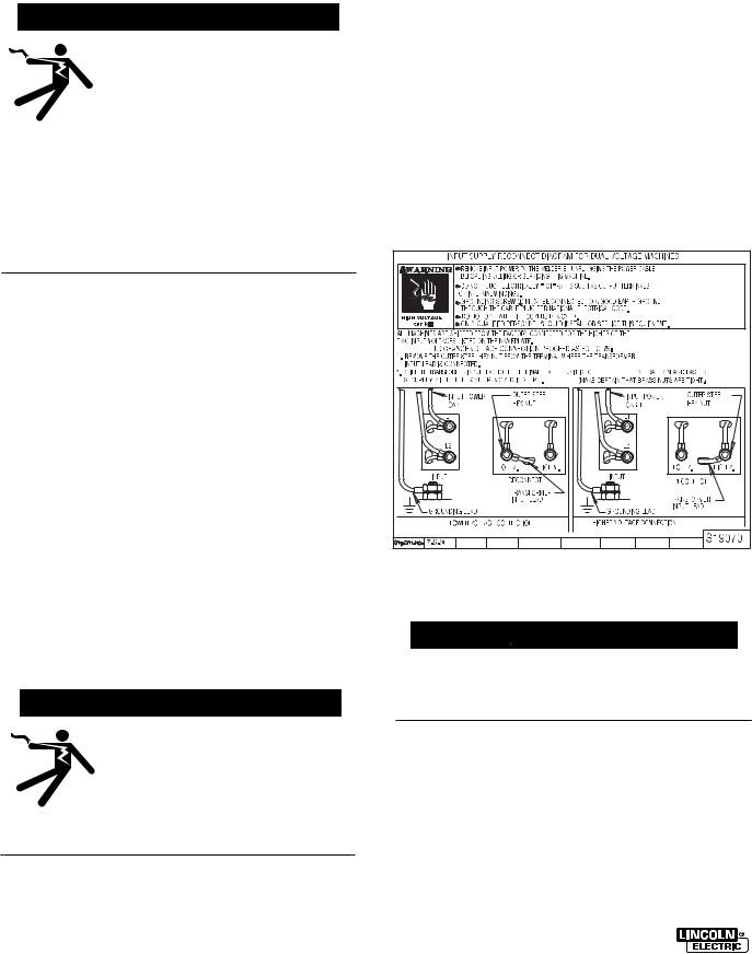
2.Models that have multiple input voltages specified on the nameplate (e.g., 208/230) are shipped connected for the higher voltage. If the welder is to be operated on lower voltage, it must be reconnected according to the instructions on the inside of the removable panel near the top left side of the rear panel. These instructions are repeated below:
INPUT POWER AND GROUNDING CONNECTIONS
 WARNING
ELECTRIC SHOCK can kill.
•Do not touch electrically live parts such as output terminals or internal wiring
•All input power must be electri-
cally disconnected before proceeding.
IDEALARC SP-255 OCT94
 WARNING
Make certain that the input power is electrically disconnected before removing the screw that holds the removable rear panel in place.
3.The 208/230 volt 60 Hz model SP-255 is shipped with a 10 ft. (3.0 m) input cable and plug connected to the welder. A matching receptacle is supplied with the machine. Mount the receptacle in a suitable location using the screws provided. Be sure it can be reached by the plug on the input cable attached to the welder. Mount with the grounding terminal at the top to allow the power cable to hang down without bending.
INSTALLATION |
A-3 |
The 230/460/575 volt 60 Hz model is not equipped with a plug, input cable or receptacle.
4.Using the following instructions have a qualified electrician connect the receptacle or cable to the input power lines and the system ground per the U.S. National Electrical Code and any applicable local codes. See the “Technical Specifications” page at the beginning of this chapter for proper wire sizes. For long runs over 100 feet (30 m), larger copper wires should be used. Fuse the two hot lines with super lag type fuses as shown in the following diagram. The center contact in the receptacle is for the grounding connection. A green wire in the input cable connects this contact to the frame of the welder.
This ensures proper grounding of the welder frame when the welder plug is inserted into the receptacle.
SINGLE PHASE INPUT SUPPLY RECONNECT DIAGRAM FOR 230/460/575 60 HZ MACHINES
|
WARNING |
|
TURN THE INPUT POWER OFF AT THE DISCONNECT SWITCH BEFORE INSTALLING |
|||
|
|
|
OR SERVICING THIS MACHINE. |
|||
|
|
|
DO NOT TOUCH ELECTRICALLY "HOT" PARTS SUCH AS OUTPUT TERMINALS |
|||
|
|
|
OR INTERNAL WINDINGS. |
|
||
|
|
|
GROUNDING SCREW |
|
|
MUST BE CONNECTED TO A GOOD EARTH GROUND PER |
|
|
|
|
|
||
|
|
|
||||
|
|
|
NATIONAL ELECTRICAL CODE. |
|||
|
|
|
DO NOT OPERATE WITH COVERS REMOVED. |
|||
|
HIGH VOLTAGE |
|||||
|
|
ONLY QUALIFIED PERSONNEL SHOULD INSTALL OR SERVICE THIS EQUIPMENT. |
||||
|
can kill |
|
||||
1.ALL MACHINES ARE SHIPPED FROM THE FACTORY CONNECTED FOR THE HIGHEST NAMEPLATED SINGLE PHASE INPUT VOLTAGE. TO CHANGE CONNECTIONS FOR A DIFFERENT INPUT VOLTAGE. RECONNECT BOTH COPPER JUMPERS PER DIAGRAM BELOW. ALWAYS CONNECT JUMPERS BETWEEN OUTER STEEL NUT AND
INNER BRASS NUT ON TERMINAL STUDS.
2.CONNECT THE INPUT POWER TO THE INPUT TERMINAL BLOCK, L1 AND L2 AT THE UPPER LEFT CORNER OF THE PANEL. TORQUE TO 16 IN-LBS.
3.CONNECT A GROUNDING LEAD TO THE GROUND STUD  ON THE MACHINE NEAR THE INPUT TERMINAL BLOCK.
SINGLE PHASE |
230V / 60HZ. |
|
|
|
460V. / 60HZ. |
|
|
575V. / 60HZ. |
||
VOLTAGE |
|
|
|
|
|
|||||
|
|
|
|
|
|
|
|
|
|
|
L1 |
L2 |
|
5 |
L1 |
L2 |
|
5 |
L1 |
L2 |
5 |
JUMPER |
4 |
2 |
|
|
|
2 |
|
|
|
|
CONNECTION |
|
|
4 |
|
|
4 |
2 |
|||
|
|
|
|
|
|
|
|
|
|
|
DIAGRAMS |
1 |
3 |
|
|
1 |
3 |
|
|
1 |
3 |
BOTH
JUMPERS
TO GROUND PER NATIONAL ELECTRICAL CODE
SINGLE PHASE INPUT POWER SUPPLY LINES
S21531-1
CONNECT TO A SYSTEM GROUND-
ING WIRE. SEE THE UNITED STATES
NATIONAL. ELECTRICAL CODE
AND/OR LOCAL CODES FOR OTHER
DETAILS AND MEANS FOR PROPER
GROUNDING.
CONNECT TO HOT WIRES OF A
THREE-WIRE, SINGLE PHASE SYS-
TEM OR TO ONE PHASE OF A TWO
OR THREE PHASE SYSTEM.
OUTPUT POLARITY CONNECTION
 WARNING
Turn the welder power switch off before changing output connection.
The welder, as shipped from the factory, is connected for electrode positive (+) polarity. This is the normal polarity for GMA welding.
If negative (–) polarity is required, interchange the connections of the two cables located in the wire drive compartment near the front panel. The electrode cable, which is attached to the wire drive, is to be connected to the negative (–) labeled terminal and the work lead, which is attached to the work clamp, is to be connected to the positive (+) labeled terminal.
GUN AND CABLE INSTALLATION
The Magnum™ 250SP gun and cable provided with the SP-255 is factory installed with a liner for .035-
.045" (0.9-1.2 mm) electrode and an .035" (0.9 mm) contact tip. Install the .045 tip (also provided) if this wire size is being used. For other wire sizes, see Gun and Cable Maintenance.
 WARNING
Turn the welder power switch off before installing gun and cable.
1.Lay the cable out straight.
2.Make sure all pins on the gun cable connector are aligned with the proper mating sockets on the front panel gun connector and then join the connectors and tighten the hand nut on the gun cable connector.
NOTE: If a gun and cable other than the Magnum 250SP is to be used, it must conform to standard European-style connector (Magnum Fast-Mate™) specifications. See diagram below.
IDEALARC SP-255

A-4 |
INSTALLATION |
Gun - END VIEW
However, the thumbswitch functions available on the Magnum 250SP gun will only be operable from the front panel keypad. The gun trigger switch must be capable of switching 5 milliamps at 15 volts DC– resistive.
 CAUTION
The gun trigger switch connected to the gun trigger control cable must be a normally open, momentary switch. The terminals of the switch must be insulated from the welding circuit. Improper operation of or damage to the SP-255 might result if this switch is common to an electrical circuit other than the SP-255 trigger circuit.
SHIELDING GAS
(For Gas Metal Arc Welding Processes)
Customer must provide cylinder of appropriate type shielding gas for the process being used.
 WARNING
CYLINDER may explode if damaged.


 Gas under pressure is explosive.


 Always keep gas cylinders in an upright position and always keep chained to undercarriage or stationary support.
See American national Standard Z49.1, “Safety in Welding and Cutting” published by the American Welding Society.
1.Set gas cylinder in rear platform of SP-255. Hook chain in place to secure cylinder to rear of welder.
2.Remove the cylinder cap. Inspect the cylinder valves for damaged threads, dirt, dust, oil or grease. Remove dust and dirt with a clean cloth.
DO NOT ATTACH THE REGULATOR IF OIL, GREASE OR DAMAGE IS PRESENT! Inform your gas supplier of this condition. Oil or grease in the presence of high pressure oxygen is explosive.
IDEALARC SP-255 OCT94
3.Stand to one side away from the outlet and open the cylinder valve for an instant. This blows away any dust or dirt which may have accumulated in the valve outlet.
 WARNING
Be sure to keep your face away from the valve outlet when “cracking” the valve.
4.Inspect the regulator for damaged threads, dirt, dust, oil or grease. Remove dust and dirt with a clean cloth.
DO NOT USE THE REGULATOR IF OIL, GREASE OR DAMAGE IS PRESENT! Have an authorized repair station clean the regulator or repair any damage.
5.Attach the flow regulator to the cylinder valve and tighten the union nut(s) securely with a wrench.
NOTE: If connecting to 100% CO2 cylinder, insert regulator adapter provided between regulator and cylinder valve. If adapter is equipped with a plastic washer, be sure it is seated for connection to the CO2 cylinder.
6.Attach one end of the inlet gas hose to the outlet fitting of the flow regulator, the other end to the SP255 rear fitting, and tighten the union nuts securely with a wrench.
7.Before opening the cylinder valve, turn the regulator adjusting knob counter-clockwise until the adjusting spring pressure is released.
8.Open the cylinder valve slowly a fraction of a turn. When the cylinder pressure gauge pointer stops moving, open the valve fully.
 WARNING
Never stand directly in front of or behind the flow regulator when opening the cylinder valve. Always stand to one side.
9.The flow regulator is adjustable. Set it for the flow rate recommended for the procedure and process being used before making the weld.

|
OPERATION |
B-1 |
Read entire Operation section before operating the SP-255.
WARNING
ELECTRIC SHOCK can kill.
•Do not touch electrically live parts or electrode with skin or wet clothing. Insulate yourself from work and ground.
•Always wear dry insulating gloves.
FUMES AND GASES can be dangerous.
•Keep your head out of fumes.
•Use ventilation or exhaust to remove fumes from breathing zone.
WELDING SPARKS can cause fire or explosion.
• Keep flammable material away.
•Do not weld on closed containers.
ARC RAYS can burn eyes and skin.
• Wear eye, ear and body protection.
Observe all safety information throughout this manual.
IDEALARC SP-255

B-2 |
OPERATION |
|
PRODUCT DESCRIPTION
The SP-255 is a complete semiautomatic constant voltage DC arc welding machine built to meet NEMA specifications. It combines a constant voltage power source and a constant speed wire feeder with a micro- computer-based controller. This forms an intelligent welding system that really puts the automatic in semiautomatic. A touch key entry system with audible feedback, along with a two-line, 32 character alphanumeric display provide user friendly control of the system.
Multilingual display capability allows the SP-255 to communicate with the user in any of the following languages: English, German, French, Spanish, or Japanese (Katakana).
RECOMMENDED PROCESSES AND EQUIPMENT
The SP-255 is recommended for GMA welding processes using 10 to 44 lb. (4.5 to 20 kg) 2" (51 mm) I.D. spools or Readi-Reel® coils of .025 through .045 (0.6-1.2 mm) solid steel using CO2, ArCO2, or ArO2 shielding gas, .035" (0.9 mm) stainless steel using ArO2 or HeArCO2 shielding gas, 3/64" (1.2 mm) aluminum using Ar shielding gas, and .045" (1.2 mm) Outershield® electrodes using CO2 or ArCO2 shielding gas, as well as .035" (0.9 mm) and .045" (1.2 mm) Innershield® self-shielded electrodes.
The SP-255 is factory equipped to feed .035" (0.9 mm) and .045" (1.2 mm) electrodes and includes a 200A, 60% duty cycle rated, 12.5 ft. (3.8 m) GMA gun and cable assembly equipped for these wire sizes. The SP-255 is factory equipped with an adjustable CO2 and Argon blend flow regulator. A supply of shielding gas is required for GMAW processes.
WELDING CAPABILITY
The SP-255 is rated at 250 amps @ 26 volts at a 35% duty cycle on a ten minute basis. It is capable of higher duty cycles at lower output currents.
LIMITATIONS
The SP-255 may not operate as designed if powered with a portable or in-plant generator.
IDEALARC SP-255
DESCRIPTION OF CONTROLS AND KEYS
POWER SWITCH
Place the lever in the “ON” position to turn the SP-255 on. When the power is on, the red LED backlighting of the LCD display will be lit, and the screen will contain a readable display. The welding setup present when the power was shut off or disconnected will be restored when the power is restored.
SETUP KEYS
DISPLAY LANGUAGE SELECTION
The SP-255 has multilingual display capability permitting the SP-255 prompts, messages, and other display information to be in any of five languages: English, German, French, Spanish, and Japanese (Katakana). The user may select the chosen language by simultaneously pressing the PROCESS Key and the appropriate Number Key per the instructions given in the appropriate language on the Keypad Instruction Decal inside the SP-255 door, also shown below:
ARROW KEYS
There are three pairs of arrow keys: left, center, and right. The up arrow keys increase the selection displayed directly above them. The down arrow keys decrease the selection displayed directly above them. All of the arrow keys have a repeat function when they

OPERATION |
B-3 |
are held closed. The left pair will automatically continue to increment or decrement the selection above it at a slow, steady rate as long as the key is pressed. The center and right pairs will continue to increment and decrement the selections above them at a slow rate, but then the rate will gradually increase until it becomes very rapid. This allows rapid setting from a small quantity to a large quantity or vice versa while maintaining an excellent resolution (i.e., 50 IPM to 600 IPM). However, when the trigger is closed, the changes will be at a steady, moderate rate to allow for proper “on the fly” control.
START MODE SELECTIONS
The SP-255 permits selection of Fast/Slow Run-In wire feed speed as well as adjustment of the start striking voltage, to optimize arc starting, using the starting screen display.
The starting screen (see Figures below) is displayed by pressing and holding both the PROCESS key and the TIMERS OFF key at the same time.
FIGURE 1
1.Run-In Speed
The SP-255 is factory set for FAST run-in (Figure 1) where the wire feed will accelerate directly to the preset speed. SLOW run-in will initially feed at 50 IPM until welding current is sensed, or for 2 seconds if feeding without welding (loading wire).
SLOW run-in may be selected using the left arrow keys which will toggle the starting screen display to SLOW (Figure 2) or back to FAST (Figure 1).
FIGURE 2
2.Start Voltage
The START voltage setting (Figure 1 or 2) may be offset from the factory programmed level (00%) by up to ±30% above or below programmed level using the right arrow keys, or from the gun thumbswitch by positioning the screen cursor beneath the START display using the IPM-VOLTS key. (see “Gun Switch Keys” in this section).
3.Spool Gun Start Mode
If using optional spool gun mode (see “Making a Weld with the Spool Gun” in Accessories section), the RUN-IN portion of the starting screen is not functional and will not be displayed. The START voltage is adjusted as described above (Figure 3).
FIGURE 3
The starting screen is exited by pressing any key on the keypad except TIMERS OFF, IPMVOLTS or any Arrow key. Closing Gun Trigger will also not clear the starting screen.
NOTE: It is not necessary to repeat the above procedure each time the unit is powered up. That is, the unit will remember the start mode settings from the previous power down and return you to that same state upon your next power up. thus, you need only perform the above procedure when you want to change the start mode settings.
When saving to Memory locations 1-5, the start mode at the time of saving will be saved into the memory location as well. Thus, the operator should be aware that when recalling a memorized procedure, he is also recalling particular start mode which will override any present start mode setting and remain in effect until either the mode is changed using the above procedure or until a memorized procedure containing another start mode is recalled.
PROCESS (WIRE/GAS) KEY
This key is used to display the Wire Type, Wire Diameter, and Welding Gas. Each combination of wire and gas dictates a unique relationship between the wire feed speed and the arc voltage. The SP-255 uses this unique relationship, along with the metal thickness, to set the proper values of wire feed speed and arc voltage. Therefore, it is very important that the wire type, wire diameter, and welding gas on the display match the actual wire type, wire diameter, and welding gas being used for the weld.
Left arrow keys—set Wire Type
JAN96 IDEALARC SP-255

B-4 |
OPERATION |
Center arrow keys—set Wire Diameter
Right arrow keys—set Welding Gas
The following 16 processes are programmed into the SP-255:
|
Wire Type |
|
Wire Diameter |
|
Welding Gas |
|||
|
|
|
|
|
|
|
|
|
|
Solid Steel |
.025 (0.6mm) |
CO2 |
|||||
|
Solid Steel |
|
|
.025 (0.6mm) |
|
|
ArCO2 |
|
|
Solid Steel |
|
|
.030 (0.8mm) |
|
|
CO2 |
|
|
Solid Steel |
|
|
.030 (0.8mm) |
|
|
ArCO2 |
|
|
Solid Steel |
|
|
.035 (0.9mm) |
|
|
CO2 |
|
|
Solid Steel |
|
|
.035 (0.9mm) |
|
|
ArCO2 |
|
|
Solid Steel |
|
|
.035 (0.9mm) |
|
|
ArO2 |
|
|
Solid Steel |
|
|
.045 (1.2mm) |
|
|
CO2 |
|
|
Solid Steel |
|
|
.045 (1.2mm) |
|
|
ArCO2 |
|
|
Stainless |
|
|
.035 (0.9mm) |
|
|
ArO2 |
|
|
Stainless |
|
|
.035 (0.9mm) |
|
|
HeArCO2 |
|
|
Aluminum (5356) |
|
|
3/64” (1.2mm) |
|
|
Argon |
|
|
Outershield® |
|
|
.045 (1.2mm) |
|
|
CO2 |
|
|
Outershield |
|
|
.045 (1.2mm) |
|
|
Ar/CO2 |
|
|
Innershield® |
|
|
.035 (0.9mm) |
|
|
None |
|
|
Innershield |
|
|
.045 (1.2mm) |
|
|
None |
|
|
|
|
|
|
|
|
|
|
|
|
|
|
|
|
|
|
|
PROCEDURE KEYS
Because design, fabrication, assembly and welding variables affect the results obtained in applying recommended procedure information, the serviceability of a product or assembly is the responsibility of the builder/user.
AUTO KEY
available sizes. (NOTE: If the spot or stitch timers are on, metal thickness is not displayed and, therefore, the left arrow keys will not function. Also, the left arrow keys do not function when the trigger is closed. (See Figures I and 2 following.)
Center arrow keys — Increases (up arrow) or decreases (down arrow) wire feed speed setting. Increasing or decreasing wire feed speed will simultaneously cause an increase or decrease in the arc voltage and can change the metal thickness setting.
Right arrow keys — Increases (up arrow) or decreases (down arrow) arc voltage setting. An up arrow indicator appears below the V in VOLTS if the arc voltage has been set higher than the recommended value, and a down arrow indicator appears below the V in VOLTS if the arc voltage is below the recommended value. No arrow indicates that you are set to the recommended value. (See Figures 4 and 5 following.)
Repressing the Auto key resets the wire feed speed and arc voltage settings to the recommended values for the metal thickness displayed. (NOTE: If the spot or stitch timers are on, metal thickness is not displayed and, therefore, the repress function does not work.)
Pressing the Auto Key once places the SP-255 into the automatic mode of operation. Auto mode provides automatic setup of the recommended wire feed speed and arc voltage based on the metal thickness selected and the process being used. The Auto mode screen displays metal thickness, set wire feed speed, the set arc voltage, and a cursor that indicates which parameter, wire feed speed, or arc voltage is being controlled by the thumbswitch on the SP-255 gun (see Gun Switches section).
Left arrow keys — Increases (up arrow) or decreases (down arrow) metal thickness setting. Increasing or decreasing metal thickness automatically increases or decreases both wire feed speed and arc voltage simultaneously. See gauge chart on instruction label on inside of SP-255 door for
IDEALARC SP-255
Figure 4 |
Figure 5 |
TYPICAL AUTO KEY PRESS SEQUENCES
Process screen is being displayed prior to pressing Auto key. The Auto key is pressed, the Auto screen is now displayed.
If the unit was in a Manual configuration (see Manual Key) when the Auto key was pressed, the audio alarm will beep three times and a message (see below) will be displayed for 2.5 seconds reminding you that the process entered into the SP-255 (see Process Key) must match the wire and gas being used. After the 2.5 second period is over, the Auto screen will be displayed with the same procedure that was in Manual.
 Loading...