


SERVICE MANUAL
(DOMESTIC)
IMPINGER CONVEYOR OVENS
IMPINGER II - ADVANTAGE SERIES
Lincoln Foodservice Products, LLC
1111 North Hadley Road
Fort Wayne, Indiana 46804
United States of America
Phone: (800) 374-3004
U.S. Fax: (888) 790-8193 • Int’l Fax: (260) 436-0735
Technical Service Hot Line
(800) 678-9511
www.lincolnfp.com
1100AdvSvc |
REV 3/20/08 |
TABLE OF CONTENTS |
|
TABLE OF CONTENTS |
2 |
SEQUENCE OF OPERATIONS |
4 |
SEQUENCE OF OPERATIONS |
5 |
SCHEMATIC 1116-000-A, 1117-000-A |
6 |
SCHEMATIC 1130-000-A / 1131-000-A |
7 |
SCHEMATIC 1132-000-A / 1133-000-A |
8 |
TROUBLESHOOTING GUIDE / GAS OVENS |
9 |
TROUBLESHOOTING GUIDE / ELECTRIC OVENS |
14 |
REMOVAL, INSTALLATION, AND ADJUSTMENT |
18 |
PARTS / GENERAL |
26 |
BLOW UP / GENERAL |
27 |
PARTS / CONTROL BOX 1116-000-A, 1117-000-A |
28 |
BLOW UP / CONTROL BOX – 1116-000-A, 1117-000-A |
29 |
PARTS / CONTROL BOX – 1130-000-A THRU 1133-000-A |
30 |
BLOW UP / CONTROL BOX – 1130-000-A THRU 1133-000-A |
31 |
PARTS / CONVEYOR & DOOR |
32 |
BLOW UP / CONVEYOR & DOOR |
33 |
PARTS / OVEN BACK ASSEMBLY |
34 |
BLOW UP / OVEN BACK ASSEMBLY |
35 |
2 |
Impinger II – Advantage Service Manual - Domestic |
SEQUENCE OF OPERATIONS
IMPINGER II ADVANTAGE
MODEL 1116-000-A / NATURAL GAS / 120 VAC / 60 HZ / 1 PHASE
MODEL 1117-000-A / L.P. GAS / 120 VAC / 60 HZ / 1 PHASE
POWER SUPPLY |
Electrical power is supplied to the oven by a three conductor cordset. Voltage |
|
from the black conductor to the white conductor is 120 VAC. The white |
|
conductor is neutral. The green conductor is ground. |
CONTROL BOX AUTO |
When the temperature in the control box reaches 120°F ± 3° (48.9°C ± 1.7°C), |
|
the |
COOL DOWN |
interrupt power to the fans when the control box temperature falls to 100°F ± 3° |
|
(37.8°C ± 1.7°C). |
MAIN FAN CIRCUIT |
Power is permanently supplied, through a 10A fuse, and through a normally |
|
closed control box hi-limit thermostat, to the normally open main fan switch. |
|
Power is also supplied to the normally open cooling fan thermostat. Closing the |
|
main fan switch supplies 120 VAC to the main fan motor, the cooling fan motor, |
|
the primary of the temperature display transformer, the heat and conveyor |
|
circuits. |
BURNER CIRCUIT |
Closing the main fan switch supplies 120 VAC to the burner blower motor. 120 |
|
VAC is also supplied, through the normally closed oven cavity hi-limit thermostat, |
|
the main fan centrifugal switch (this switch closes when main fan reaches |
|
approximately 1600 RPM) to the electronic temperature control and to the |
|
primary of the burner transformer. |
IGNITION CONTROL |
The ignition control operates on both 24 VAC and 120 VAC. When the control is |
|
energized by 24 VAC from the transformer, 120 VAC is switched by the ignition |
|
control to the hot surface ignitor for 45 seconds for the hot surface ignitor warm |
|
up. The ignitor glows red, 24 VAC is switched to the gas valve which opens and |
|
ignition should now occur. |
TEMPERATURE CONTROL |
When the centrifugal switch of the main fan motor closes, power is applied to the |
|
temperature control. The 1K ohm temperature pot is adjusted to desired |
|
temperature. The thermocouple will provide varying millivolts to the temperature |
|
controller. The temperature controller supplies 120 VAC to the solenoid valve at |
|
intermittent intervals to maintain desired temperature. The heat lamp is |
|
energized with the solenoid valve. |
CONVEYOR DRIVE |
Closing the on/off switch supplies 120 VAC to the motor control board. AC volts |
|
are converted to DC volts and are supplied to the conveyor motor at terminals A+ |
|
and A-. |
|
Adjustment of the speed control potentiometer will change resistance at terminals |
|
P1 and P2 varying the DC voltage to the motor. The speed of the conveyor |
|
motor will increase or decrease as the DC voltage from the board increases or |
|
decreases respectively. |
NOTE: |
The conveyor control uses a sensor and magnet, mounted on the conveyor |
|
motor that senses the motor speed. Any change in motor load (±RPM) is |
|
detected by the sensor and the voltage to the motor is adjusted accordingly. |
Temperature Display |
Closing the switch supplies 120 VAC to the primary of the temperature display |
|
transformer. The secondary of this transformer supplies 12 VAC to the temperature |
|
display. The thermocouple supplies D.C. millivolts to the temperature display. The |
|
display converts this millivolt reading to a temperature reading. |
Impinger II –Advantage Service Manual - Domestic |
3 |
SEQUENCE OF OPERATIONS
|
1130-000-A / 208V / SINGLE PHASE |
|
1131-000-A / 240V / SINGLE PHASE |
|
1132-000-A / 208V / THREE PHASE |
|
1133-000-A / 240V / THREE PHASE |
POWER SUPPLY |
Electrical power to be supplied to the oven by a three-conductor service on single |
|
phase and a four-conductor service on three phase. |
|
Black conductor is Hot |
|
Red conductor is Hot |
|
Orange conductor is Hot (Used on 3 phase only) |
|
Green conductor is ground. |
CONTROL BOX AUTO COOL DOWN |
When the temperature in the control box reaches 120°F ± 3°F (48.9°F ± 1.7°C), |
|
the cooling fan thermostat will switch power to the cooling fans. The thermostat |
|
will interrupt power to the fans when the temperature falls to 100°F ± 3°F (37°C ± |
|
1.7°C). |
MAIN FAN CIRCUIT |
Power is permanently supplied through the 10A fuses, through the normally |
|
closed control box high limit thermostat, to the normally open main fan switch. |
|
Power is also supplied to the normally open cooling fan thermostat. Closing the |
|
main fan switch supplies 208/240 VAC to the main fan motor, the cooling fan |
|
motor, to the primary of the temperature display transformer and to the heat and |
|
conveyor circuits. |
HEATER CIRCUIT |
Closing the fan switch supplies 208/240 VAC, through the normally open air |
|
pressure switch (closed by air pressure from the main fan) through the normally |
|
closed oven cavity hi-limit thermostat, to the electronic temperature control. The |
|
1K ohm temperature pot is adjusted to desired temperature. The thermocouple |
|
will provide varying millivolts to the temperature controller. The temperature |
|
control then supplies 208/240 VAC to the coil of the contactor at intermittent |
|
intervals to maintain the desired temperature. The heat lamp is energized with |
|
the contactor. |
CONVEYOR DRIVE |
Closing the on/off switch supplies 120 VAC to the motor control board. AC volts |
|
are converted to DC volts and are supplied to the conveyor motor at terminals A+ |
|
and A-. |
|
Adjustment of the speed control potentiometer will change resistance at terminals |
|
P1 and P2 varying the DC voltage to the motor. The speed of the conveyor |
|
motor will increase or decrease as the DC voltage from the board increases or |
|
decreases respectively. |
NOTE: |
The conveyor control uses a sensor and magnet, mounted on the conveyor |
|
motor that senses the motor speed. Any change in motor load (±RPM) is |
|
detected by the sensor and the voltage to the motor is adjusted accordingly. |
Temperature Display |
Closing the switch supplies 120 VAC to the primary of the temperature display |
|
transformer. The secondary of this transformer supplies 12 VAC to the |
|
temperature display. The thermocouple supplies D.C. millivolts to the |
|
temperature display. The display converts this millivolt reading to a temperature |
|
reading. |
4 |
Impinger II – Advantage Service Manual - Domestic |

SCHEMATIC 1116-000-A, 1117-000-A
Impinger II –Advantage Service Manual - Domestic |
5 |
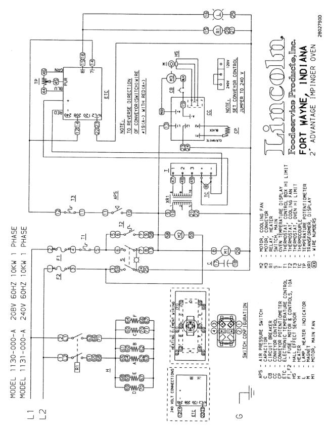
SCHEMATIC 1130-000-A / 1131-000-A
6 |
Impinger II – Advantage Service Manual - Domestic |
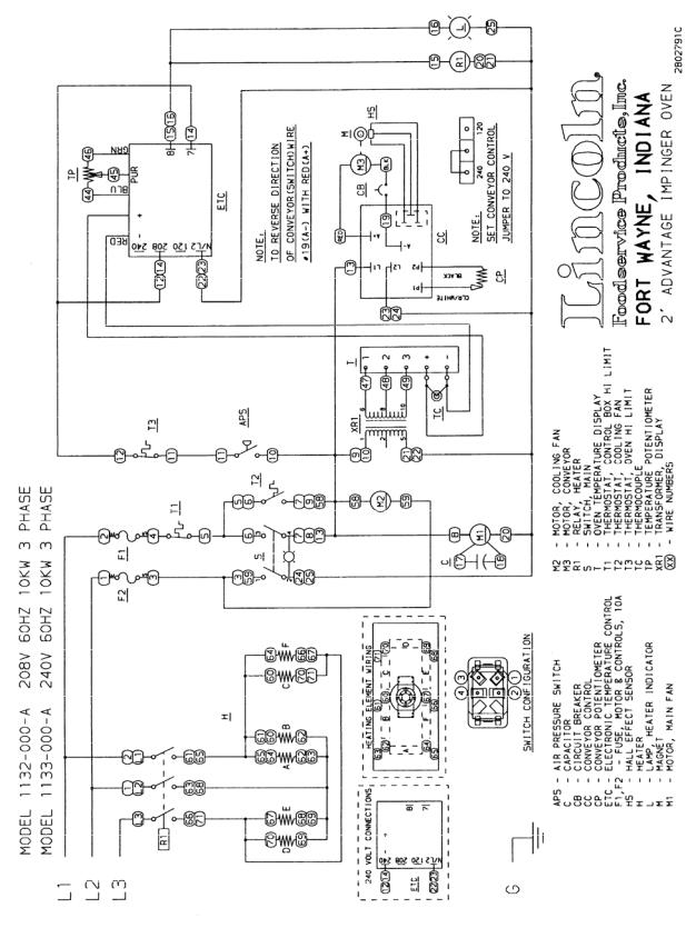
SCHEMATIC 1132-000-A / 1133-000-A
Impinger II –Advantage Service Manual - Domestic |
7 |
TROUBLESHOOTING GUIDE / GAS OVENS
|
MODEL 1116-000-A |
NATURAL GAS |
120 VAC |
60 HZ |
1 PHASE |
|||
|
MODEL 1117-000-A |
LP GAS |
|
120 VAC |
60 HZ |
1 PHASE |
||
|
|
|
|
|
|
|
||
|
SYMPTOM |
POSSIBLE CAUSE |
EVALUATION |
|
|
|
||
|
Oven fan will not run |
Incoming Power Supply |
Check breakers, reset it required. Check power plug |
|||||
|
|
|
|
to be sure it is firmly in receptacle. Measure |
||||
|
|
|
|
incoming power/call power company if needed. |
||||
|
|
Fuse, 10 Amp |
|
Check, replace if necessary. |
|
|
||
|
|
Fuse Holder |
|
Check, replace if necessary. |
|
|
||
|
|
Hi Limit Thermostat-Control |
Check for voltage on both sides of the switch. |
|||||
|
|
Box |
|
Terminals are normally closed. If open, reset and |
||||
|
|
|
|
test oven for proper operation. If thermostat will not |
||||
|
|
|
|
hold and control box temperature is not exceeding |
||||
|
|
|
|
140°F (60°), replace thermostat. |
||||
|
|
Main Fan Switch |
|
Check continuity between switch terminals. |
||||
|
|
Main Fan Motor |
|
Check for opens, shorts, or grounds. WITH POWER |
||||
|
|
|
|
OFF turn fan blade to check for locked rotor. |
||||
|
|
Capacitor |
|
Check for shorts or grounds. |
|
|
||
|
|
|
|
WARNING: Capacitor has a stored charge, |
||||
|
|
|
|
discharge before testing. |
|
|
||
|
No control box cooling |
Incoming Power |
|
Check main circuit breakers, reset if required, call |
||||
|
|
|
|
power company if needed. |
|
|
||
|
|
Main Fan Switch |
|
Check continuity between switch terminals |
||||
|
|
Cooling Fan |
|
120 VAC should now be at the fan motor. If voltage |
||||
|
|
|
|
is present, check motors for shorts or opens. WITH |
||||
|
|
|
|
POWER OFF: Check for locked rotor. |
||||
|
No automatic control |
Incoming Power Supply |
Check circuit breakers, |
|
|
|||
|
box cooling |
|
|
reset if required. Call the power company if needed. |
||||
|
|
Cooling Fan Thermostat |
Check the cooling fan thermostat. (Thermostat |
|||||
|
|
|
|
closes at 120°F and opens at 100°F). With the |
||||
|
|
|
|
cooling fan thermostat preheated, check for |
||||
|
|
|
|
continuity. If switch is open, replace. |
||||
|
|
Cooling Fan |
|
120 VAC should be at the motor. If voltage is |
||||
|
|
|
|
present, check motor for shorts, opens, or grounds. |
||||
|
|
|
|
WITH POWER OFF: check for locked rotor. |
||||
|
Oven will not heat |
Gas Supply |
|
Check for adequate gas supply and closed manual |
||||
|
|
|
|
gas shut offs. Also, check flexible gas line |
||||
|
|
|
|
connection. |
|
|
|
|
|
|
Main Fan |
|
If not operating, refer to "Oven fan will not run". |
||||
|
|
High Limit Oven Cavity |
Terminals are normally closed. If |
|||||
|
|
Thermostat |
|
open, push in reset button and retest. If thermostat |
||||
|
|
|
|
will not hold for maximum oven temperature, and |
||||
|
|
|
|
oven is not exceeding temperature dial setting, |
||||
|
|
|
|
check for proper location of capillary bulb in its |
||||
|
|
|
|
spring holder. If above checks okay, replace hi-limit |
||||
|
|
|
|
thermostat. |
|
|
|
|
|
|
Centrifugal Switch |
Check for 120 VAC at lead #9 |
|
|
|||
|
|
of Main Fan Motor |
(located at 6 pin connector in raceway near the main |
|||||
|
|
|
|
fan motor) to neutral. If no voltage is present, and |
||||
|
|
|
|
motor is running, replace motor. |
||||
8 |
|
|
|
Impinger II – Advantage Service Manual - Domestic |
||||
|
Burner Blower Motor |
Visually check to see if motor is running. If not, |
|
|
check for 120 VAC to motor at motor connector (wire |
|
|
#5 and #22). If voltage is not present, trace wiring |
|
|
back to fan switch. If voltage is present and motor is |
|
|
not running, check for opens, shorts, or grounds. |
|
|
Also, WITH POWER OFF: check for locked rotor. |
|
Transformer, Burner |
Primary is 120 VAC with 24 VAC secondary. If 120 |
|
|
VAC is not present, trace wiring back to Main Fan |
|
|
Centrifugal Switch. If 120 VAC is present, check for |
|
|
24 VAC at secondary of transformer. If no voltage is |
|
|
present, replace transformer. |
|
Centrifugal Switch of Burner |
Check of 120 VAC at motor connector, on wire #13 |
|
Blower Motor |
to neutral. If voltage is not present, trace wiring back |
|
|
to transformer. If voltage is not present and motor is |
|
|
running, replace the burner blower motor. |
|
Ignition Control |
24 volts should be present at 24 volt terminals. If not |
|
|
present, trace wiring back to centrifugal switch. |
|
|
When 24 VAC is supplied, the control switches 120 |
|
|
VAC from L1 and L2 to the hot surface ignitor. if 120 |
|
|
VAC is not present at L1 and L2, trace wiring |
|
|
back to fan switch. If 24 VAC and 120 VAC are |
|
|
present and 120 VAC is not across the hot surface |
|
|
ignitor terminals, replace the ignition control. |
|
Hot Surface Ignitor |
If 120 VAC is present at hot surface ignitor terminals, |
|
|
visually check to see that the ignitor is heating. |
|
|
(Ignitor may be viewed through the port glass in end |
|
|
of burner tube.) The ignitor should glow bright red. |
|
|
If the ignitor does not heat, replace the ignitor. |
|
Ignition Control |
After 45 seconds of hot surface ignitor pre-heat, the |
|
|
ignition control will switch 24 VAC to the gas control |
|
|
valves. Check for 24 VAC output from ignition |
|
|
control, across terminals marked "valve" and "valve |
|
|
ground". If no voltage is present, replace ignition |
|
|
control. |
|
Gas Control Valves |
When 24 VAC is supplied to the gas control valve, |
|
|
the valve should open. Check for gas pressure at |
|
|
the manifold tap located just before the burner. If |
|
|
there is no pressure, check the incoming gas supply |
|
|
to be sure all manual valves are open and flexible |
|
|
gas hose is properly connected. If gas is present |
|
|
and coils of gas valve are energized, the gas valve is |
|
|
probably defective. |
Flame will not stay lit |
Hot Surface Ignitor |
Six seconds after the gas valve opens, ignition must |
|
|
occur. if flame is not detected, the ignition control |
|
|
will shut off and lock out. To reset the ignition |
|
|
control, turn off the burner switch for 45 seconds, |
|
|
then turn on the burner switch to retry ignition. The |
|
|
ignition control requires a minimum of 0.8 D.C. |
|
|
microamps. To check flame sensing operation, |
|
|
connect a digital multimeter (capable of measuring |
|
|
D.C. micro-amps) between the "ground" terminal on |
|
|
ignition control and the ground lead. |
|
|
NOTE: This is a current measurement and the |
|
|
meter must be connected in series. If these |
|
|
readings are not achieved, replace the hot surface |
|
|
ignitor. |
|
|
NOTE: The D.C. micro amp test must be conducted |
|
|
with the oven in low flame (bypass) operation. Turn |
|
|
the temperature control to the lowest setting. |
Impinger II –Advantage Service Manual - Domestic |
9 |
|
Power Supply |
If there is sufficient micro-amp current, but the flame |
|
|
will not stay lit, check for proper polarity of the 120 |
|
|
VAC power supply. |
|
Ignition Control |
If there is sufficient micro-amp current, and the 120 |
|
|
VAC polarity is correct, but the flame will not stay lit, |
|
|
replace ignition control. |
|
|
NOTE: Check for proper ground connection on |
|
NOTE: Flame should be lit at |
ignition control. |
|
|
|
|
this time. |
|
Low flame is on, |
Temperature Control |
Check for 120 VAC at terminal #7 |
but no main flame |
|
to neutral on temperature control. If no voltage, |
|
|
trace voltage back through centrifugal switch and hi- |
|
|
limit. Turn the temperature adjustment knob to |
|
|
maximum temperature position and check for 120 |
|
|
VAC at the load terminal #8 and neutral. If 120 VAC |
|
|
is present and unit is not heating, refer to |
|
|
"Temperature Solenoid Valve" for next check. If 120 |
|
|
VAC is not present, proceed. |
|
Thermocouple Probe |
WITH POWER ON AND THERMOCOUPLE LEADS |
|
|
ATTACHED TO THE TEMPERATURE CONTROL |
|
|
BOARD: Measure the D.C. millivolt output of these |
|
|
leads. Refer to thermocouple chart in Section D for |
|
|
proper readings. If these readings are not achieved, |
|
|
replace the thermocouple. |
|
Temperature Set |
Disconnect the potentiometer leads |
|
Potentiometer |
from the board. Place ohm meter test leads on the |
|
|
blue and green pot leads. Reading should be 1 K |
|
|
ohms. Place meter leads across the blue and purple |
|
|
pot leads and rotate knob from high to low. Repeat |
|
|
on green and purple leads. Check for even rise and |
|
|
fall of ohms reading to insure that there are no open |
|
|
or dead spots in the potentiometer. Check each |
|
|
lead to ground for shorts. Replace pot if it does not |
|
|
meet the above test. |
|
Temperature Solenoid |
If 120 VAC is present on the |
|
Valve |
temperature control board at load terminal #8 to |
|
|
neutral, check for voltage at temperature regulation |
|
|
valve. If voltage is present, listen for valve to open |
|
|
and close. Also check for opens or shorts in the coil. |
|
|
Replace as necessary. |
Intermittent Heating |
Thermal/Overload of Main Fan |
The main fan motor and the burner blower motor are |
|
and Burner Blower Motors |
equipped with internal thermal protection and will |
|
|
cease to operate if over heating occurs. As the |
|
|
motors overheat and then cool, this will cause the |
|
|
units to cycle on and off intermittently. This may be |
|
|
caused by improper ventilation or preventive |
|
|
maintenance. Also, most of the problems listed |
|
|
under "Oven will not heat" can cause intermittent |
|
|
failure. |
Conveyor will not run |
Voltage Supply |
Check incoming voltage supply at line 1 to neutral. |
|
|
There should be a voltage reading of 120 VAC. If |
|
|
not present, check breakers. |
|
10 Amp Fuse |
Check and/or replace. |
|
Fuseholder |
Check and/or replace. |
|
Fan Switch |
See procedure for checking on Page 10. |
10 |
Impinger II – Advantage Service Manual - Domestic |
|
Speed Adjustment |
This is a 0 to 10 K ohm, 1 turn potentiometer. With |
|
Potentiometer |
power off, remove the black and white pot leads |
|
|
from the motor control board at terminals P1, P2. |
|
|
Place the meter leads on the black lead (P2) and on |
|
|
the white lead (P1). Rotating the pot., slowly, from |
|
|
low to high, the meter readings should show an even |
|
|
transition from 0 to 10 K ohms ± 5%. There should |
|
|
be no dead or open spots through out the 1 turn of |
|
|
the pot. Check both leads to ground. There should |
|
|
be no continuity to ground. If any of the above |
|
|
checks fail, replace the pot. |
|
DC Motor Control Board |
Check for 120 VAC input to the control board at |
|
|
terminals L1 and L2. If not present, check wiring |
|
|
back to the oven fan switch. If 120 VAC is present |
|
|
at L1 and L2, check both fuses on control board (8A |
|
|
line and 1A armature), check the VDC output at |
|
|
terminals A+ and A-. If 120 VAC is present at |
|
|
terminals L1 and L2 and DC voltage is present at |
|
|
A+ and A-, but the motor does not run, check gear |
|
|
motor as follows: |
|
Conveyor Gear Motor |
If DC voltage is present at A+ and A- and the motor |
|
|
does not run, first check the mini breaker and then |
|
|
the conveyor. Refer to the next possible cause. |
|
|
Check the leads to the motor for evidence of any |
|
|
shorts or opens, and each lead to ground. Check |
|
|
motor brushes. From the top of the motor, rotate |
|
|
motor shaft to determine if there is a locked rotor or |
|
|
a locked gear box (use care so magnet and H.S. |
|
|
board are not damaged). Replace motor as needed. |
|
Conveyor |
Check for any mechanical misalignment. Also, |
|
|
check for worn bearings. A conveyor belt that is |
|
|
over tightened will cause excessive bearing wear |
|
|
and sometimes, irregular speed. |
Conveyor speed varying or |
Power Supply |
Check power supply at the DC control board for the |
intermittent |
|
120 VAC at board terminals L1 and L2. |
|
Motor Control Board |
Place the test meter probes on terminals A+ and A-. |
|
|
(With speed potentiometer set to maximum speed |
|
|
(Approximately 2 min.) The meter reading should be |
|
|
approximately 100 VDC (±3%), if voltage is not |
|
|
steady within limits, then the board is probably bad. |
|
|
Always check the speed pot., be sure it is okay |
|
|
before changing a board. This test is not always |
|
|
100% accurate as this test is not performed at |
|
|
operating speeds. However, this test is the best |
|
|
method currently available. |
|
DC Gearmotor |
If the DC control board is steady then the problem |
|
|
may be the motor or gearbox. Check the brushes in |
|
|
the motor for excessive arching and/or unusual |
|
|
wear. Check the motor and gearbox from instruction |
|
|
located on Page 11 under "possible cause" listing |
|
|
"conveyor gear motor." |
|
Magnet |
Check to insure that the magnet (cemented to shaft |
|
|
of conveyor drive motor) has not been damaged, or |
|
|
come loose from motor shaft. Replace as needed. |
|
Hall Effect Sensor |
Check for any physical damage to hall effect sensor |
|
|
(mounted on conveyor drive motor.) Check all wiring |
|
|
and connections for damage. Check all connections |
|
|
for tightness or proper location and check all wiring |
|
|
for visible damage. Replace as needed. Connect |
|
|
new hall effect to system and check for steady |
|
|
operation. |
Impinger II –Advantage Service Manual - Domestic |
11 |
|
 Loading...