


RETURN TO MAIN INDEX
IM526-B
INVERTEC™V300-PRO December,1999
For use with machines Code 10256 and 10257.
Safety Depends on You
Lincoln arc welding and cutting equipment is designed and built with safety in mind. However, your overall safety can be increased by proper installation ... and thoughtful operation on your part. DO NOT INSTALL, OPERATE OR REPAIR THIS EQUIPMENT WITHOUT READING THIS MANUAL AND THE SAFETY PRECAUTIONS CONTAINED THROUGHOUT. And, most importantly, think before you act and be careful.
Date of Purchase:
Serial Number:
Code Number:
Model:
Where Purchased:
OPERATOR’S MANUAL
•World's Leader in Welding and Cutting Products •
•Sales and Service through Subsidiaries and Distributors Worldwide •
Cleveland, Ohio 44117-1199 U.S.A. TEL: 216.481.8100 FAX: 216.486.1751 WEB SITE: www.lincolnelectric.com
WARNING
ARC WELDING can be hazardous.
PROTECT YOURSELF AND OTHERS FROM POSSIBLE SERIOUS INJURY OR DEATH. KEEP CHILDREN AWAY. PACEMAKER WEARERS SHOULD CONSULT WITH THEIR DOCTOR BEFORE OPERATING.
Read and understand the following safety highlights. For additional safety information it is strongly recommended that you purchase a copy of “Safety in Welding & Cutting - ANSI Standard Z49.1” from the American Welding Society, P.O. Box 351040, Miami, Florida 33135 or CSA Standard W117.2-1974. A Free copy of “Arc Welding Safety” booklet E205 is available from the Lincoln Electric Company, 22801 St. Clair Avenue, Cleveland, Ohio 44117-1199.
BE SURE THAT ALL INSTALLATION, OPERATION, MAINTENANCE, AND REPAIR PROCEDURES ARE PERFORMED ONLY BY QUALIFIED INDIVIDUALS.
ELECTRIC SHOCK can
kill.
1.a. The electrode and work (or ground) circuits are electrically “hot” when the welder is on.
Do not touch these “hot” parts with your bare skin or wet clothing. Wear dry, hole-free gloves to insulate hands.
1.b. Insulate yourself from work and ground using dry insulation. Make certain the insulation is large enough to cover your full area of physical contact with work and ground.
In addition to the normal safety precautions, if welding must be performed under electrically hazardous conditions (in damp locations or while wearing wet clothing; on metal structures such as floors, gratings or scaffolds; when in cramped positions such as sitting, kneeling or lying, if there is a high risk of unavoidable or accidental contact with the workpiece or ground) use the following equipment:
•Semiautomatic DC Constant Voltage (Wire) Welder.
•DC Manual (Stick) Welder.
•AC Welder with Reduced Voltage Control.
1.c. In semiautomatic or automatic wire welding, the electrode, electrode reel, welding head, nozzle or semiautomatic welding gun are also electrically“hot”.
1.d. Always be sure the work cable makes a good electrical connection with the metal being welded. The connection should be as close as possible to the area being welded.
1.e. Ground the work or metal to be welded to a good electrical (earth) ground.
1.f. Maintain the electrode holder, work clamp, welding cable and welding machine in good, safe operating condition. Replace damaged insulation.
1.g. Never dip the electrode in water for cooling.
1.h. Never simultaneously touch electrically “hot” parts of electrode holders connected to two welders because voltage between the two can be the total of the open circuit voltage of both welders.
1.i. When working above floor level, use a safety belt to protect yourself from a fall should you get a shock.
1.j. Also see Items 4.c. and 6.
ARC RAYS can burn.
2.a. Use a shield with the proper filter and cover plates to protect your eyes from sparks and the rays of the arc when welding or observing open arc welding. Headshield and filter lens should conform to ANSI Z87. I standards.
2.b. Use suitable clothing made from durable flame-resistant material to protect your skin and that of your helpers from the arc rays.
2.c. Protect other nearby personnel with suitable non-flammable screening and/or warn them not to watch the arc nor expose themselves to the arc rays or to hot spatter or metal.
FUMES AND GASES can be dangerous.
3.a. Welding may produce fumes and gases haz-
ardous to health. Avoid breathing these fumes and gases.When welding, keep your head out of the fume. Use enough ventilation and/or exhaust at the arc to keep fumes
and gases away from the breathing zone. When welding with electrodes which require special ventilation such as stainless or hard facing (see instructions on container or MSDS) or on lead or cadmium plated steel and other metals or coatings which produce highly toxic fumes, keep exposure as low as possible and below Threshold Limit Values (TLV) using local exhaust or mechanical ventilation. In confined spaces or in some circumstances, outdoors, a respirator may be required. Additional precautions are also required when welding on galvanized steel.
3.b. Do not weld in locations near chlorinated hydrocarbon vapors coming from degreasing, cleaning or spraying operations. The heat and rays of the arc can react with solvent vapors to form phosgene, a highly toxic gas, and other irritating products.
3.c. Shielding gases used for arc welding can displace air and cause injury or death. Always use enough ventilation, especially in confined areas, to insure breathing air is safe.
3.d. Read and understand the manufacturer’s instructions for this equipment and the consumables to be used, including the material safety data sheet (MSDS) and follow your employer’s safety practices. MSDS forms are available from your welding distributor or from the manufacturer.
3.e. Also see item 7b.

 WELDING SPARKS can
 cause fire or explosion.
4.a..Remove fire hazards from the welding area. If this is not possible, cover them to prevent the welding sparks from starting a fire. Remember that welding sparks and hot
materials from welding can easily go through small cracks and openings to adjacent areas. Avoid welding near hydraulic lines. Have a fire extinguisher readily available.
4.b. Where compressed gases are to be used at the job site, special precautions should be used to prevent hazardous situations. Refer to “Safety in Welding and Cutting” (ANSI Standard Z49.1) and the operating information for the equipment being used.
4.c. When not welding, make certain no part of the electrode circuit is touching the work or ground. Accidental contact can cause overheating and create a fire hazard.
4.d. Do not heat, cut or weld tanks, drums or containers until the proper steps have been taken to insure that such procedures will not cause flammable or toxic vapors from substances inside. They can cause an explosion even though they have been “cleaned.” For information purchase “Recommended
Safe Practices for the Preparation for Welding and Cutting of
Containers and Piping That Have Held Hazardous Substances”, AWS F4.1 from the American Welding Society (see address above).
4.e. Vent hollow castings or containers before heating, cutting or welding. They may explode.
Apr. ‘93 |
– 2 – |
4.f. Sparks and spatter are thrown from the welding arc. Wear oil free protective garments such as leather gloves, heavy shirt, cuffless trousers, high shoes and a cap over your hair. Wear ear plugs when welding out of position or in confined places.
Always wear safety glasses with side shields when in a welding area.
4.g. Connect the work cable to the work as close to the welding area as practical. Work cables connected to the building framework or other locations away from the welding area increase the possibility of the welding current passing through lifting chains, crane cables or other alternate circuits. This can create fire hazards or overheat lifting chains or cables until they fail.
4.h. Also see item 7c.
CYLINDER may explode


 if damaged.
5.a. Use only compressed gas cylinders contain-
ing the correct shielding gas for the process
 used and properly operating regulators designed for the gas and pressure used. All hoses, fittings, etc. should be suitable for the application and
maintained in good condition.
5.b. Always keep cylinders in an upright position securely chained to an undercarriage or fixed support.
5.c. Cylinders should be located:
•Away from areas where they may be struck or subjected to physical damage.
•A safe distance from arc welding or cutting operations and any other source of heat, sparks, or flame.
5.d. Never allow the electrode, electrode holder or any other electrically “hot” parts to touch a cylinder.
5.e. Keep your head and face away from the cylinder valve outlet when opening the cylinder valve.
5.f. Valve protection caps should always be in place and hand tight except when the cylinder is in use or connected for use.
5.g. Read and follow the instructions on compressed gas cylinders, associated equipment, and CGA publication P-l, “Precautions for Safe Handling of Compressed Gases in
Cylinders,”available from the Compressed Gas Association 1235 Jefferson Davis Highway, Arlington, VA 22202.
FOR ELECTRICALLY powered equipment.
6.a. Turn off input power using the disconnect switch at the fuse box before working on the equipment.
6.b. Install equipment in accordance with the U.S. National
Electrical Code, all local codes and the manufacturer’s recommendations.
6.c. Ground the equipment in accordance with the U.S. National Electrical Code and the manufacturer’s recommendations.
FOR ENGINE powered equipment.
7.a. Turn the engine off before troubleshooting and maintenance work unless the maintenance work requires it to be running.
---------------------------------------------------------------------------------------
7.b. Operate engines in open, well-ventilated areas or vent the engine exhaust fumes outdoors.
---------------------------------------------------------------------------------------
7.c.Do not add the fuel near an open flame welding arc or when the engine is running. Stop the engine and allow it to cool before refueling to prevent spilled fuel from vaporizing on contact with hot engine parts and igniting. Do not spill fuel when filling tank. If fuel is spilled, wipe it up and do not start engine until fumes have been eliminated.
---------------------------------------------------------------------------------------
7.d. Keep all equipment safety guards, covers and devices in position and in good repair. Keep hands, hair, clothing and tools away from V-belts, gears, fans and all other moving parts when starting, operating or repairing equipment.
7.e. In some cases it may be necessary to remove safety guards to perform required maintenance. Remove guards only when necessary and replace them when the maintenance requiring their removal is complete. Always use the greatest care when working near moving parts.
7.f. Do not put your hands near the engine fan. Do not attempt to override the governor or idler by pushing on the throttle control rods while the engine is running.
7.g. To prevent accidentally starting gasoline engines while turning the engine or welding generator during maintenance work, disconnect the spark plug wires, distributor cap or magneto wire as appropriate.
---------------------------------------------------------------------------------------
7.h. To avoid scalding, do not remove the radiator pressure cap when the engine is hot.
ELECTRIC AND MAGNETIC FIELDS
may be dangerous
8.a. Electric current flowing through any conductor causes localized Electric and
Magnetic Fields (EMF). Welding current creates EMF fields around welding cables and welding machines.
8.b. EMF fields may interfere with some pacemakers, and welders having a pacemaker should consult their physician before welding.
8.c. Exposure to EMF fields in welding may have other health effects which are now not known.
8d. All welders should use the following procedures in order to minimize exposure to EMF fields from the welding circuit:
8.d.1. Route the electrode and work cables together - Secure them with tape when possible.
8.d.2. Never coil the electrode lead around your body.
8.d.3. Do not place your body between the electrode and work cables. If the electrode cable is on your right side, the work cable should also be on your right side.
8.d.4. Connect the work cable to the workpiece as close as possible to the area being welded.
8.d.5. Do not work next to welding power source.
– 3 – |
Mar. ‘93 |

PRÉCAUTIONS DE SÛRETÉ
Pour votre propre protection lire et observer toutes les instructions et les précautions de sûreté specifiques qui parraissent dans ce manuel aussi bien que les précautions de sûreté générales suivantes:
Sûreté Pour Soudage A L’Arc
1.Protegez-vous contre la secousse électrique:
a.Les circuits à l’électrode et à la piéce sont sous tension quand la machine à souder est en marche. Eviter toujours tout contact entre les parties sous tension et la peau nue ou les vétements mouillés. Porter des gants secs et sans trous pour isoler les mains.
b.Faire trés attention de bien s’isoler de la masse quand on soude dans des endroits humides, ou sur un plancher metallique ou des grilles metalliques, principalement dans
les positions assis ou couché pour lesquelles une grande partie du corps peut être en contact avec la masse.
c.Maintenir le porte-électrode, la pince de masse, le câble de soudage et la machine à souder en bon et sûr état defonctionnement.
d.Ne jamais plonger le porte-électrode dans l’eau pour le refroidir.
e.Ne jamais toucher simultanément les parties sous tension des porte-électrodes connectés à deux machines à souder parce que la tension entre les deux pinces peut être le total de la tension à vide des deux machines.
f.Si on utilise la machine à souder comme une source de courant pour soudage semi-automatique, ces precautions pour le porte-électrode s’applicuent aussi au pistolet de soudage.
2.Dans le cas de travail au dessus du niveau du sol, se protéger contre les chutes dans le cas ou on recoit un choc. Ne jamais enrouler le câble-électrode autour de n’importe quelle partie du corps.
3.Un coup d’arc peut être plus sévère qu’un coup de soliel, donc:
a.Utiliser un bon masque avec un verre filtrant approprié ainsi qu’un verre blanc afin de se protéger les yeux du rayonnement de l’arc et des projections quand on soude ou quand on regarde l’arc.
b.Porter des vêtements convenables afin de protéger la peau de soudeur et des aides contre le rayonnement de l‘arc.
c.Protéger l’autre personnel travaillant à proximité au soudage à l’aide d’écrans appropriés et non-inflammables.
4.Des gouttes de laitier en fusion sont émises de l’arc de soudage. Se protéger avec des vêtements de protection libres de l’huile, tels que les gants en cuir, chemise épaisse, pantalons sans revers, et chaussures montantes.
5.Toujours porter des lunettes de sécurité dans la zone de soudage. Utiliser des lunettes avec écrans lateraux dans les
zones où l’on pique le laitier.
6.Eloigner les matériaux inflammables ou les recouvrir afin de prévenir tout risque d’incendie dû aux étincelles.
7.Quand on ne soude pas, poser la pince à une endroit isolé de la masse. Un court-circuit accidental peut provoquer un échauffement et un risque d’incendie.
8.S’assurer que la masse est connectée le plus prés possible de la zone de travail qu’il est pratique de le faire. Si on place la masse sur la charpente de la construction ou d’autres endroits éloignés de la zone de travail, on augmente le risque de voir passer le courant de soudage par les chaines de levage, câbles de grue, ou autres circuits. Cela peut provoquer des risques d’incendie ou d’echauffement des chaines et des câbles jusqu’à ce qu’ils se rompent.
9.Assurer une ventilation suffisante dans la zone de soudage. Ceci est particuliérement important pour le soudage de tôles galvanisées plombées, ou cadmiées ou tout autre métal qui produit des fumeés toxiques.
10.Ne pas souder en présence de vapeurs de chlore provenant d’opérations de dégraissage, nettoyage ou pistolage. La chaleur ou les rayons de l’arc peuvent réagir avec les vapeurs du solvant pour produire du phosgéne (gas fortement toxique) ou autres produits irritants.
11.Pour obtenir de plus amples renseignements sur la sûreté, voir le code “Code for safety in welding and cutting” CSA Standard W 117.2-1974.
PRÉCAUTIONS DE SÛRETÉ POUR LES MACHINES À SOUDER À TRANSFORMATEUR ET À REDRESSEUR
1.Relier à la terre le chassis du poste conformement au code de l’électricité et aux recommendations du fabricant. Le dispositif de montage ou la piece à souder doit être branché à une bonne mise à la terre.
2.Autant que possible, I’installation et l’entretien du poste seront effectués par un électricien qualifié.
3.Avant de faires des travaux à l’interieur de poste, la debrancher à l’interrupteur à la boite de fusibles.
4.Garder tous les couvercles et dispositifs de sûreté à leur place.
– 4 – |
Mar. ‘93 |
TABLE OF CONTENTS |
|
|
Page |
Safety Precautions ............................................................................................................. |
2-4 |
Introductory Information ....................................................................................................... |
6 |
Product Description.............................................................................................................. |
7 |
Specifications....................................................................................................................... |
7 |
Installation ......................................................................................................................... |
7-10 |
Safety Precautions ........................................................................................................ |
7 |
Location ......................................................................................................................... |
7 |
Electrical Installation...................................................................................................... |
7 |
Input Voltage Setup ....................................................................................................... |
8 |
Power Cord Connection ................................................................................................ |
8 |
Connection of Wire Feeders to Invertec ..................................................................... |
8-10 |
Output Cables & Plugs ................................................................................................. |
10 |
Operating Instructions ...................................................................................................... |
11-13 |
Safety Precautions ....................................................................................................... |
11 |
Controls Description and Function............................................................................. |
11-13 |
Maintenance..................................................................................................................... |
13-14 |
Capacitor Discharge Procedure ................................................................................... |
13 |
Routine Maintenance.................................................................................................... |
13 |
Periodic Maintenance ................................................................................................... |
14 |
Troubleshooting Guide ..................................................................................................... |
14-20 |
Matched Parts..................................................................................................................... |
20 |
Switch P.C. Board Replacement Procedure ....................................................................... |
20 |
Replacement of Power Modules and Output Diodes ....................................................... |
20-21 |
Connection Diagrams....................................................................................................... |
22-31 |
Wiring Diagrams............................................................................................................... |
32-33 |
Parts Lists ...................................................................................................................... |
appendix |
– 5 –

for selecting a QUALITY product by Lincoln Electric. We want you Thank You to take pride in operating this Lincoln Electric Company product
••• as much pride as we have in bringing this product to you!
Please Examine Carton and Equipment For Damage Immediately
When this equipment is shipped, title passes to the purchaser upon receipt by the carrier. Consequently, Claims for material damaged in shipment must be made by the purchaser against the transportation company at the time the shipment is received.
Please record your equipment identification information below for future reference. This information can be found on your machine nameplate.
Model Name & Number _____________________________________
Code & Serial Number _____________________________________
Date of Purchase _____________________________________
Whenever you request replacement parts for or information on this equipment always supply the information you have recorded above.
Read this Operators Manual completely before attempting to use this equipment. Save this manual and keep it handy for quick reference. Pay particular attention to the safety instructions we have provided for your protection. The level of seriousness to be applied to each is explained below:
 WARNING
This statement appears where the information must be followed exactly to avoid serious personal injury or loss of life.
 CAUTION
This statement appears where the information must be followed to avoid minor personal injury or damage to this equipment.
– 6 –

PRODUCT DESCRIPTION
The Invertec V300-PRO is a 300 amp arc welding power source that utilizes single or three phase input power to produce either constant voltage or constant current outputs. The V300-PRO is designed for 60 Hz supply systems. The welding response of the Invertec has been optimized for GMAW, SMAW, TIG and FCAW processes. It is designed to be used with the LN-25 and LN-7 semiautomatic wire feeders.
SPECIFICATIONS
Product |
Ordering |
Input AC |
Rated DC Output |
Input Amps at Rated DC Output |
Output |
Weight |
Dimensions |
||||
Name |
Information |
Voltage |
Amps/Volts/Duty Cycle |
|
|
|
|
Range |
with Gun |
HxWxD |
|
208 |
230 |
460 |
575 |
||||||||
|
|
|
|
(continuous) |
(net) |
|
|||||
|
|
|
|
|
|
|
|
|
|||
|
|
|
|
|
|
|
|
|
|
|
|
|
|
208/230/460 |
300A / 32V / 60%(1) |
48 |
43 |
24 |
|
|
|
|
|
|
|
3 Phase |
250A / 30V / 100%(1) |
37 |
33 |
19 |
|
|
|
|
|
|
|
60 Hz |
300A / 35/39/41V /60%(2) |
49 |
48 |
28 |
|
|
|
18.7*x10.8x |
|
Invertec |
K1349-3 |
|
|
|
|
|
|
|
|
22.2” |
|
|
|
|
|
|
|
|
|
||||
V300- |
|
208/230/460 |
250A / 30V / 60%(1) |
69 |
62 |
38 |
|
AMPS |
64 lbs. |
(475x274x |
|
PRO |
|
1 Phase |
160A / 28V / 100%(1) |
53 |
47 |
29 |
|
5-350 |
(29 kg) |
564 mm) |
|
|
|
60 Hz |
250A / 37/41/43V / 60%(2) |
75 |
67 |
42 |
|
|
|
|
|
|
|
|
|
|
|
|
|
|
|
* Includes |
|
|
|
|
|
|
|
|
|
|
|
||
|
|
575 |
300A / 32V / 60%(1) |
|
|
|
20 |
|
|
handle |
|
|
K1349-4 |
3 Phase |
250A / 30V / 100%(1) |
|
|
|
16 |
|
|
|
|
|
|
60 Hz |
300A / 36V / 60%(2) |
|
|
|
22 |
|
|
|
|
|
|
|
|
|
|
|
|
|
|
|
|
(1 )NEMA Class I Rated Output / Based on a 10 min. Period .
(2 )Lincoln plus rating.
* Overall Height Including Handle, (16.4” (417mm without handle).
INSTALLATION
 WARNING
ELECTRIC SHOCK can kill.
•Have an electrician install and service this equipment.
•Turn the input power off at the fuse box before working on equipment.
•Do not touch electrically hot parts.
---------------------------------------------------------------------
LOCATION
The Invertec has been designed with many features to protect it from harsh environments. Even so, it is important that simple preventative measures are followed in order to assure long life and reliable operation.
•The machine must be located where there is free circulation of clean air such that air movement into the sides and out the bottom and front will not be restricted. Dirt and dust that can be drawn into the machine should be kept to a minimum. Failure to observe these precautions can result in excessive operating temperatures and nuisance shutdown of the Invertec.
•Keep machine dry. Shelter from rain and snow. Do not place on wet ground or in puddles.
ELECTRICAL INSTALLATION
1.The Invertec should be connected only by a qualified electrician. Installation should be made in accordance with the U.S. National Electrical Code, all local codes and the information detailed below.
2.Single voltage, 575 VAC machines, can only be connected to 575 VAC. No internal reconnection for other input voltages is possible.
3.Initial 208 VAC and 230 VAC operation will require
avoltage panel setup, as will later reconnection back to 460 VAC:
a.Open the access panel on the right side of the machine.
b.For 208 or 230: Position the large switch to 200-230.
For 460: Position the large switch to 380-460.
c.Move the “A” lead to the appropriate terminal.
– 7 –
INPUT VOLTAGE SETUP
 CAUTION
DO NOT ATTEMPT TO POWER THIS UNIT FROM THE AUXILIARY POWER SUPPLY OF AN ENGINE WELDER.
•Special protection circuits may operate, causing loss of output.
•The supply from engine welders often has excessive voltage peaks because the voltage waveform is usually triangular shaped instead of sinusoidal.
•If voltage peaks from the engine welder exceed 380V, the input circuits of this machine protecting the filter capacitors, FETS and other components
from damage will not be energized .
---------------------------------------------------------------------
RECONNECT PROCEDURE |
|
|
|
|
|
|
|
|
|
|
|
|
|
|
|
|
|
|
|
|
|
|
|
|
|
|
|
|
|
.Disconnect input power before |
|||||||||||||
1. |
BE SURE POWER SWITCH IS OFF. |
|
|
|
|
|
|
||||||||||||||
|
|
|
|
|
|
inspecting or servicing machine. |
|||||||||||||||
|
|
|
|
|
|
|
|
||||||||||||||
2. |
CONNECT LEAD ’A’ TO DESIRED |
|
|
|
|
|
|
.Do not operate with wraparound |
|||||||||||||
|
INPUT VOLTAGE RANGE. |
|
|
|
|
|
|
removed. |
|||||||||||||
.Do not touch electrically live parts.
440-460V |
|
. Only qualified persons should install, |
|
|
’A’ |
||
380-415V |
use or service this equipment. |
||
|
220-230V
IF MACHINE CEASES TO OPERATE (NO METER, NO FAN)
200-208V  AND THERE IS NO OTHER KNOWN FAILURE: CHECK FUSE; REPLACE WITH A 3 AMP SLOW BLOW ONLY.
3. POSITION SWITCH TO DESIRED INPUT VOLTAGE RANGE.
|
|
|
|
|
|
|
|
|
|
|
|
|
|
|
|
|
|
VOLTAGE=380-460V |
|
|
|
|
|
|
|
|
|
|
|
|
|
|
|
|
VOLTAGE=200-230V |
||
|
|
|
|
|
|
|
|
|
|
|
|
|
|
|
|
|
|
|
|
|
|
|
|
|
|
|
|
|
|
|
|
|
|
|
|
|
|
|
|
|
|
|
|
|
|
|
|
|
|
|
|
|
|
|
|
|
|
|
|
|
|
|
|
|
|
|
|
|
|
|
|
|
|
|
|
THE LINCOLN ELECTRIC CO. CLEVELAND, OHIO U.S.A. |
9 - 11 - 92 |
|
|
|
|
|
|
|
|
|
|
|
|
|
|
S20324 |
|||||||||||||||||||||
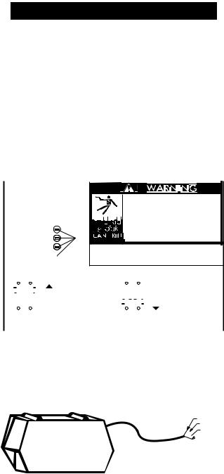
POWER CORD CONNECTION
A 10 ft. (3.0m) power cord is provided and wired into the machine. Follow the power cord connection instructions. Incorrect connection may result in equipment damage.
BLACK
GREEN
RED

 WHITE
WHITE
Single Phase Input
1.Connect green lead to ground per U.S. National Electrical Code.
2.Connect black and white leads to power.
3.Wrap red lead with tape to provide 600V insulation.
Three Phase Input
1.Connect green lead to ground per U.S. National Electrical Code.
2.Connect black, red and white leads to power.
Install in accordance with all local and national electric codes.
Recommended Fuse Sizes Based On The U.S.
National Electrical Code And Maximum
Machine Outputs
|
|
Fuse Size in Amps |
|
Input Volts(1) |
(Time Delay Fuses) |
|
|
|
3 phase |
208 |
60 |
50/60 Hz |
230 |
60 |
|
460 |
40 |
|
|
|
1 phase |
208(2) |
85 |
50/60 Hz |
230(2) |
80 |
|
460 |
50 |
|
|
|
3 phase |
575 |
30 |
60 Hz |
|
|
|
|
|
(1)Input voltage must be within ±10% of rated value.
(2)When operating on these inputs, at outputs exceeding 200A/60% or 165A/100%, the input line cord should be changed to an input conductor of 6 AWG or larger.
CONNECTION OF WIRE FEEDERS TO THE INVERTEC
(Note: IEC units do not have 110 VAC auxiliary power).
LN-25 Connection Instructions
1.Turn the Invertec power switch “off”.
2.Connect the electrode cable to the output terminal of polarity required by electrode. Connect the work lead to the other terminal.
3.LN-25 with remote control options K431 and K432. Use K876 adapter with K432 cable or modify K432 cable with K867 universal adapter plug. See connection diagram S19899 and S19309 or S19405 at the back of this manual.
4.Place the local-remote switch in the “remote” position if output control is desired at the wire feeder rather than the Invertec. (LN-25 must have K431 and K432 options for remote output control operation).
LN-7 Connection Instructions
1.Turn the Invertec power switch “off”.
2.Connect the K480 control cable from the LN-7 to the Invertec control cable connector. The control cable connector is located at the rear of the Invertec.
3.Connect the electrode cable to the output terminal of polarity required by electrode. Connect the work lead to the other terminal.
4.Place the local-remote switch in the “local” position to allow output control at the Invertec. (K864
– 8 – |
– |
remote control adapter and K857 remote control are required for remote output control).
5.Set the meter polarity switch on the rear of the Invertec to coincide with wire feeder polarity used. The wire feeder will now display the welding voltage.
6.If K480 is not available, see connection diagram S19404 for modification of K291 or K404 LN-7 input cable with K867 universal adapter plug.
General Instructions for Connection of Wire Feeders to Invertec
Wire feeders other than LN-7 and LN-25 may be used provided that the auxiliary power supply capacity of the Invertec is not exceeded. K867 universal adapter plug is required. See connection diagram S19406 and S19386 at the back of this manual for more information.
Remote Control of Invertec
Remote control K857, hand amptrol K963 and foot amptrol K870 require K864 remote control adapter. See 19309 instruction at the back of this manual for connection information.
K954-1 MIG PULSER
The MIG Pulser is a hand-held “pendant” type GMAW Pulsing option for the V300 Power Source. Refer to the Mig Pulser’s IM manual (IM555) for connection information.
Parallel Operation
The Invertec’s are operable in parallel in both CC and CV modes. For best results, the currents of each machine should be reasonably well shared. As an example, with two machines set up in parallel for a 400 amp procedure, each machine should be set to deliver approximately 200 amps, not 300 amps from one and 100 amps from the other. This will minimize nuisance shutdown conditions. In general, more than two machines in parallel will not be effective due to the voltage requirements of procedures in that power range.
To set machine outputs, start with output control pots and arc force/pinch pots in identical positions. If running in a CC mode, adjust outputs and arc forces to maintain current sharing while establishing the proper output current. In CV modes, the pots in identical positions. Then switch the machine meters to amps and adjust one of the output control pots for current balance. Check the voltage and if readjustment is necessary, repeat the current balancing step. Pinch settings should also be kept identical on the machines.
K900-1 DC TIG Starter Connection
This versatile new kit was made to mate with the Invertec.
A control cable assembly is supplied with the kit to connect the kit to an Invertec. The cable can be connected, either end, at the DC TIG Starter kit and at the Invertec by attaching to the 14-pin Amphenols on the backs of each unit. Refer to diagram S20405 at the back of this manual.
A negative output cable assembly is also supplied with the DC TIG Starter kit to connect the kit with the Invertec’s negative output terminal.
All Magnum™ one and two piece water-cooled torches with 7/8 left-hand threads and gas-cooled torches with 7/8 and 5/16 right-hand threads can be connected to the starter kit.
To secure the DC TIG Starter kit to the bottom of the Invertec and for more detailed instructions, refer to the K900-1 manual.
– 9 – |
MAR97 |
LN-9 GMA Connection Instructions
1.Turn the Invertec power switch “off”.
2.Connect the K596 control cable assembly from the LN-9 GMA to the Invertec control cable connector. The control cable connector is located at the rear of the Invertec.
3.Connect the electrode cable to the output terminal of polarity required by electrode. Connect the work lead to the other terminal.
4.Place the local-remote switch in the “remote” position to allow output control at the LN-9 GMA.
5.Set the meter polarity switch on the rear of the Invertec to coincide with wire feeder polarity used. The wire feeder will now display the welding voltage.
6.K608-1 adapter is required in LN-9 GMA for LN-9 type control. K608-1 is installed in line with P10 connection at the LN-9 GMA voltage board. See diagram S20607 at the back of this manual.
7.K442-1 Pulse Power Filter Board is also required for GMAW, but should be disconnected for FCAW.
8.If K596 is not available, see connection diagram S20608 at the back of this manual for modification of K196 LN-9 GMA input cable with K867 universal adapter plug.
Output Cables
Select the output cable size based upon the following chart.
Cable sizes for Combined Length of Electrode and Work Cable (Copper) 75° rated:
Duty |
|
Length Up |
61-76m |
Cycle |
Current |
61m (200 ft.) |
(200-250 ft.) |
|
|
|
|
100% |
250 |
1/0 |
1/0 |
60% |
300 |
1/0 |
2/0 |
|
|
|
|
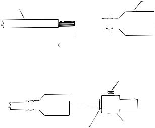
Quick Disconnect Plugs
A quick disconnect system is used for the welding cable connections. The welding plug included with the machine is designed to accept a welding cable size of 1/0 to 2/0.
1. Remote 25mm (1 in.) of welding cable insulation.
2.Slide rubber boot onto cable end. The boot end may be trimmed to match the cable diameter. Soap or other lubricant will help to slide the boot over the cable.
BOOT
WELDING CABLE
 25 mm
25 mm 
 TRIM
TRIM
1 in. 
3.Slide the copper tube into the brass plug.
4.Insert cable into copper tube.
SET SCREW
BRASS PLUG
COPPER TUBE
5.Tighten set screw to collapse copper tube. Screw must apply pressure against welding cable. The top of the set screw will be well below the surface of the brass plug after tightening.
6.Slide rubber boot over brass plug. The rubber boot must be positioned to completely cover all electrical surfaces after the plug is locked into the receptacle.
– 10 –
OPERATING INSTRUCTIONS
 WARNING
ELECTRIC SHOCK can kill.
• Do not touch electrically live parts or electrode with skin or wet clothing.
•Insulate yourself from work and ground.
•Always wear dry insulating gloves.
------------------------------------------------------------------------
FUMES AND GASES can be dangerous.
• Keep your head out of fumes.
• Use ventilation or exhaust to remove fumes from breathing zone.
------------------------------------------------------------------------
WELDING SPARKS can cause fire or 
 explosion.
•Keep flammable material away.
•Do not weld on closed containers.
------------------------------------------------------------------------
ARC RAYS can burn eyes and skin.
• Wear eye, ear and body protection.
------------------------------------------------------------
See additional warning information at front of this operator’s manual.
-----------------------------------------------------------
DUTY CYCLE
The Invertec is rated at 300 amps, 60% duty cycle for 3 phase inputs (based on a 10 minute cycle). It is also rated at 250 amps, 100% duty cycle.
CONTROL FUNCTION / OPERATION
Power Switch - Place the lever in the “ON” position to energize the machine. When the power is on, the digital meter will activate and the fan will operate.
OFF
Output Control - This controls the output voltage in the CV modes and output current in the CC modes.
Control is provided over the entire output range of the power source with 1 turn of the control knob. This control may be adjusted while under load to change power source output.
OUTPUT
Local/Remote Switch - Place in the “LOCAL” position to allow output adjustment at the machine. Place in the “REMOTE” position to allow output adjustment at the wire feeder or with a remote control option package.
REMOTE
Digital Meter Switch - Select either “A” for amps or “V” for volts to display welding current or voltage on the meter.
When welding current is not present, the meter will display the set current for the CC modes or the set voltage for the CV modes. This set reading is an indication of machine control setting. For a more precise process reading, read meter during actual welding.
Mode Switch
GTAW Optimized for both scratch start and HiFreq kit use.
CC SOFT Best for EXX18 thru EXX28 stick electrodes.
CC Crisp Use this mode for stick welding with EXX10 thru EXX14 electrodes. Nonwelding applications such as resistive heating or output tests with resistive loads should be done in this mode with Arc Force Control set to minimum.
– 11 –
CV FCAW This setting has been optimized for Innershield® and Outershield® flux-cored electrodes.
CV GMAW Short circuit, glob and spray transfer solid wire and gas welding are done in this mode. Low end procedures, less than 17V, may operate better in the FCAW mode. Voltage in the GMAW mode can become erratic when welding is attempted using voltages equal to or less than 17V DC+.
SMAW |
|
CRISP |
FCAW |
SMAW |
|
SOFT |
GMAW |
GTAW |
|
Output Terminals Switch
For processes and equipment that require energized machine terminals (stick, TIG, air-carbon arc cutting or hot tip LN-25), set the Output Terminals Switch to “ON” position.
Set to the REMOTE (OFF) position when using LN-25 with K431 and K432 options or LN-7 which will allow the gun trigger to energize the welding terminals.
ON
OUTPUT
TERMINALS
REMOTE
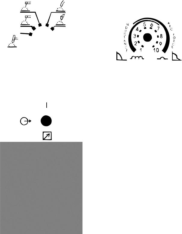
Arc Force / Inductance Control
This control functions in all modes except GTAW. For CC modes, this control acts as an Arc Force adjustment. The arc is soft at the minimum settings and more forceful or driving at the maximum settings. Higher spatter levels may be present at the maximum settings.
For CV modes, this control will set the degree of “pinch effect” which predominantly affects short circuit transfer. In FCAW, the maximum setting is generally preferred. With GMAW, the upper half of the range is preferred with CO2 or high content CO2 mixed. The lower half is for inert gas mixes.
Recommended Arc Force / Inductance Settings
For Selected Applications
Full Range Is 1-10,
1 Is Very Soft, 10 Is Very Crisp
|
|
Nominal |
Recommended |
Mode |
Process |
Setting |
Adjustment Range |
|
|
|
|
CC SMAW 1 |
EXX18 thru |
5 |
1 (gentle, may stick) to 9 |
|
EXX28 stick |
|
(forceful, more spatter) |
|
|
|
|
CC SMAW 2 |
EXX10 thru |
6 |
3 to 10 |
|
EXX14 stick |
|
|
|
Air Carbon Arc |
1 |
None |
|
Cutting |
|
|
|
|
|
|
CV FCAW |
Innershield or |
10 |
None |
|
Outershield |
|
|
|
Air Carbon Arc |
1 |
None |
|
Cutting |
|
|
|
|
|
|
CV GMAW* |
CO2 or 25% CO2 |
7.5 |
5 to 10 |
|
or similar |
|
|
|
gas mixes |
|
|
|
98% Ar-2% O2Ar, |
5 |
1 to 10 |
|
90% He-7.5% Ar |
|
|
|
2.5% CO2 and |
|
|
|
other |
|
|
|
predominantly |
|
|
|
inert gases |
|
|
|
|
|
|
* 1 = Lowest pinch, highest inductance and least spatter. 10 = Highest pinch, lowest inductance and most spatter.
– 12 – |
– |
 Loading...