


RANGER 300 D
IM571-A
RETURN TO MAIN MENU
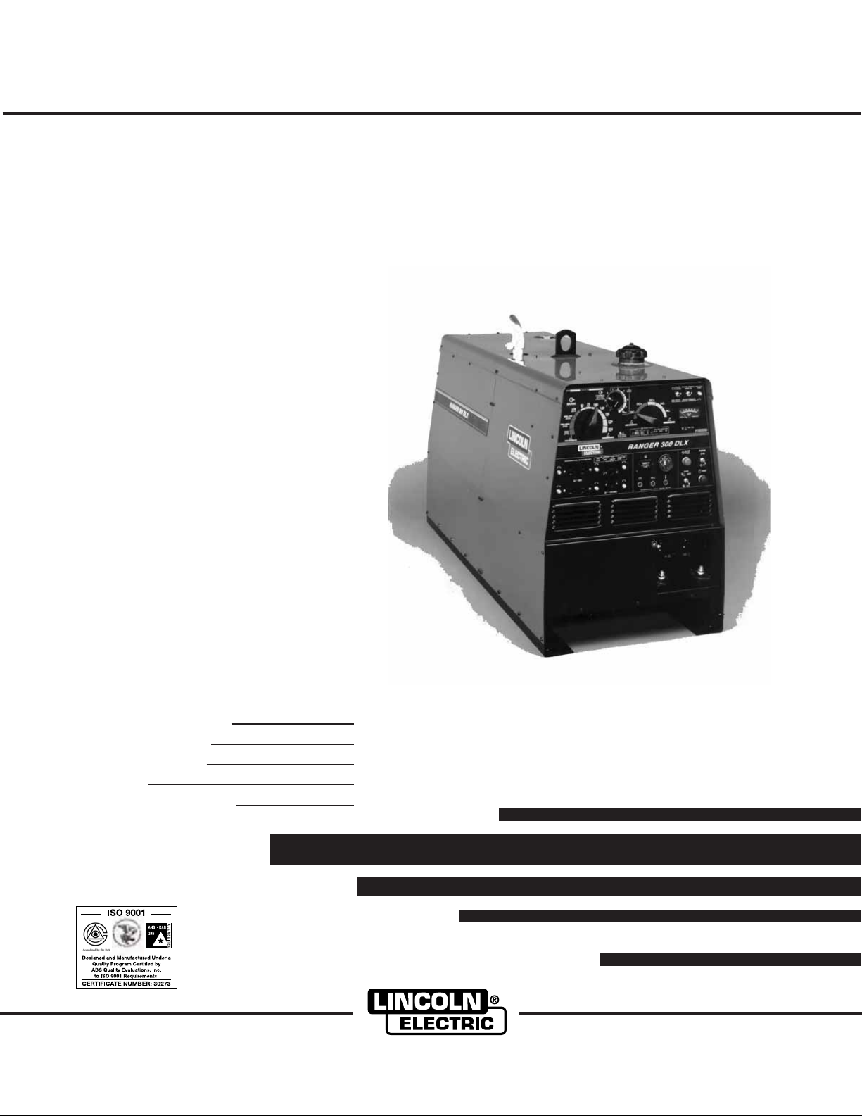
RANGER 300 D and 300 DLX
For use with machines having Code Numbers:
Safety Depends on You
Lincoln arc welding and cutting
equipment is designed and built
with safety in mind. However, your
overall safety can be increased by
proper installation ... and thoughtful operation on your part. DO
NOT INSTALL, OPERATE OR
REPAIR THIS EQUIPMENT
WITHOUT READING THIS
MANUAL AND THE SAFETY
PRECAUTIONS CONTAINED
THROUGHOUT. And, most
importantly, think before you act
and be careful.
™
February, 2003
10399; 10400; 10850
Date of Purchase:
Serial Number:
Code Number:
Model:
Where Purchased:
Cleveland, Ohio 44117-1199 U.S.A. TEL: 216.481.8100 FAX: 216.486.1751 WEB SITE: www.lincolnelectric.com
OPERATOR’S MANUAL
Copyright © 2003 Lincoln Global Inc.
• World's Leader in Welding and Cutting Products •
• Sales and Service through Subsidiaries and Distributors Worldwide •
i
SAFETY
i
WARNING
CALIFORNIA PROPOSITION 65 WARNINGS
Diesel engine exhaust and some of its constituents
are known to the State of California to cause cancer, birth defects, and other reproductive harm.
The Above For Diesel Engines
ARC WELDING CAN BE HAZARDOUS. PROTECT YOURSELF AND OTHERS FROM POSSIBLE SERIOUS INJURY OR DEATH.
KEEP CHILDREN AWAY. PACEMAKER WEARERS SHOULD CONSULT WITH THEIR DOCTOR BEFORE OPERATING.
Read and understand the following safety highlights. For additional safety information, it is strongly recommended that you
purchase a copy of “Safety in Welding & Cutting - ANSI Standard Z49.1” from the American Welding Society, P.O. Box
351040, Miami, Florida 33135 or CSA Standard W117.2-1974. A Free copy of “Arc Welding Safety” booklet E205 is available
from the Lincoln Electric Company, 22801 St. Clair Avenue, Cleveland, Ohio 44117-1199.
BE SURE THAT ALL INSTALLATION, OPERATION, MAINTENANCE AND REPAIR PROCEDURES ARE
PERFORMED ONLY BY QUALIFIED INDIVIDUALS.
The engine exhaust from this product contains
chemicals known to the State of California to cause
cancer, birth defects, or other reproductive harm.
The Above For Gasoline Engines
FOR ENGINE
powered equipment.
1.a. Turn the engine off before troubleshooting and maintenance
work unless the maintenance work requires it to be running.
____________________________________________________
1.b. Operate engines in open, well-ventilated
areas or vent the engine exhaust fumes
outdoors.
____________________________________________________
1.c. Do not add the fuel near an open flame
welding arc or when the engine is running.
Stop the engine and allow it to cool before
refueling to prevent spilled fuel from vaporizing on contact with hot engine parts and
igniting. Do not spill fuel when filling tank. If
fuel is spilled, wipe it up and do not start
engine until fumes have been eliminated.
____________________________________________________
1.d. Keep all equipment safety guards, covers and devices in
position and in good repair.Keep hands, hair, clothing and
tools away from V-belts, gears, fans and all other moving
parts when starting, operating or repairing equipment.
____________________________________________________
1.e. In some cases it may be necessary to remove safety
guards to perform required maintenance. Remove
guards only when necessary and replace them when the
maintenance requiring their removal is complete.
Always use the greatest care when working near moving
parts.
___________________________________________________
1.f. Do not put your hands near the engine fan.
Do not attempt to override the governor or
idler by pushing on the throttle control rods
while the engine is running.
1.h. To avoid scalding, do not remove the
radiator pressure cap when the engine is
hot.
ELECTRIC AND
MAGNETIC FIELDS
may be dangerous
2.a. Electric current flowing through any conductor causes
localized Electric and Magnetic Fields (EMF). Welding
current creates EMF fields around welding cables and
welding machines
2.b. EMF fields may interfere with some pacemakers, and
welders having a pacemaker should consult their physician
before welding.
2.c. Exposure to EMF fields in welding may have other health
effects which are now not known.
2.d. All welders should use the following procedures in order to
minimize exposure to EMF fields from the welding circuit:
2.d.1.
Route the electrode and work cables together - Secure
them with tape when possible.
2.d.2. Never coil the electrode lead around your body.
2.d.3. Do not place your body between the electrode and
work cables. If the electrode cable is on your right
side, the work cable should also be on your right side.
___________________________________________________
1.g. To prevent accidentally starting gasoline engines while
turning the engine or welding generator during maintenance
work, disconnect the spark plug wires, distributor cap or
magneto wire as appropriate.
2.d.4. Connect the work cable to the workpiece as close as
possible to the area being welded.
2.d.5. Do not work next to welding power source.
Mar ‘95
ii
SAFETY
ii
ELECTRIC SHOCK can
kill.
3.a. The electrode and work (or ground) circuits
are electrically “hot” when the welder is on.
Do not touch these “hot” parts with your bare
skin or wet clothing. Wear dry, hole-free
gloves to insulate hands.
3.b. Insulate yourself from work and ground using dry insulation.
Make certain the insulation is large enough to cover your full
area of physical contact with work and ground.
In addition to the normal safety precautions, if welding
must be performed under electrically hazardous
conditions (in damp locations or while wearing wet
clothing; on metal structures such as floors, gratings or
scaffolds; when in cramped positions such as sitting,
kneeling or lying, if there is a high risk of unavoidable or
accidental contact with the workpiece or ground) use
the following equipment:
• Semiautomatic DC Constant Voltage (Wire) Welder.
• DC Manual (Stick) Welder.
• AC Welder with Reduced Voltage Control.
3.c. In semiautomatic or automatic wire welding, the electrode,
electrode reel, welding head, nozzle or semiautomatic
welding gun are also electrically “hot”.
3.d. Always be sure the work cable makes a good electrical
connection with the metal being welded. The connection
should be as close as possible to the area being welded.
3.e. Ground the work or metal to be welded to a good electrical
(earth) ground.
3.f.
Maintain the electrode holder, work clamp, welding cable and
welding machine in good, safe operating condition. Replace
damaged insulation.
3.g. Never dip the electrode in water for cooling.
3.h. Never simultaneously touch electrically “hot” parts of
electrode holders connected to two welders because voltage
between the two can be the total of the open circuit voltage
of both welders.
3.i. When working above floor level, use a safety belt to protect
yourself from a fall should you get a shock.
3.j. Also see Items 6.c. and 8.
ARC RAYS can burn.
4.a. Use a shield with the proper filter and cover
plates to protect your eyes from sparks and
the rays of the arc when welding or observing
open arc welding. Headshield and filter lens
should conform to ANSI Z87. I standards.
4.b. Use suitable clothing made from durable flame-resistant
material to protect your skin and that of your helpers from
the arc rays.
4.c. Protect other nearby personnel with suitable, non-flammable
screening and/or warn them not to watch the arc nor expose
themselves to the arc rays or to hot spatter or metal.
FUMES AND GASES
can be dangerous.
5.a. Welding may produce fumes and gases
hazardous to health. Avoid breathing these
fumes and gases.When welding, keep
your head out of the fume. Use enough
ventilation and/or exhaust at the arc to keep
fumes and gases away from the breathing zone. When
welding with electrodes which require special
ventilation such as stainless or hard facing (see
instructions on container or MSDS) or on lead or
cadmium plated steel and other metals or coatings
which produce highly toxic fumes, keep exposure as
low as possible and below Threshold Limit Values (TLV)
using local exhaust or mechanical ventilation. In
confined spaces or in some circumstances, outdoors, a
respirator may be required. Additional precautions are
also required when welding on galvanized steel.
5.b.
Do not weld in locations near chlorinated hydrocarbon
coming from degreasing, cleaning or spraying operations.
The heat and rays of the arc can react with solvent vapors
form phosgene, a highly toxic gas, and other irritating products.
5.c. Shielding gases used for arc welding can displace air and
cause injury or death. Always use enough ventilation,
especially in confined areas, to insure breathing air is safe.
5.d. Read and understand the manufacturer’s instructions for this
equipment and the consumables to be used, including the
material safety data sheet (MSDS) and follow your
employer’s safety practices. MSDS forms are available from
your welding distributor or from the manufacturer.
5.e. Also see item 1.b.
vapors
to
Mar ‘95
iii
SAFETY
iii
WELDING SPARKS can
cause fire or explosion.
6.a.
Remove fire hazards from the welding area.
If this is not possible, cover them to prevent
the welding sparks from starting a fire.
materials from welding can easily go through small cracks
and openings to adjacent areas. Avoid welding near
hydraulic lines. Have a fire extinguisher readily available.
6.b. Where compressed gases are to be used at the job site,
special precautions should be used to prevent hazardous
situations. Refer to “Safety in Welding and Cutting” (ANSI
Standard Z49.1) and the operating information for the
equipment being used.
6.c. When not welding, make certain no part of the electrode
circuit is touching the work or ground. Accidental contact
can cause overheating and create a fire hazard.
6.d. Do not heat, cut or weld tanks, drums or containers until the
proper steps have been taken to insure that such procedures
will not cause flammable or toxic vapors from substances
inside. They can cause an explosion even
been “cleaned”. For information, purchase “Recommended
Safe Practices for the
Containers and Piping That Have Held Hazardous
Substances”, AWS F4.1 from the American Welding Society
(see address above).
6.e. Vent hollow castings or containers before heating, cutting or
welding. They may explode.
Sparks and spatter are thrown from the welding arc. Wear oil
6.f.
free protective garments such as leather gloves, heavy shirt,
cuffless trousers, high shoes and a cap over your hair. Wear
ear plugs when welding out of position or in confined places.
Always wear safety glasses with side shields when in a
welding area.
6.g. Connect the work cable to the work as close to the welding
area as practical. Work cables connected to the building
framework or other locations away from the welding area
increase the possibility of the welding current passing
through lifting chains, crane cables or other alternate circuits. This can create fire hazards or overheat lifting chains
or cables until they fail.
6.h. Also see item 1.c.
Remember that welding sparks and hot
though
they have
Preparation
for Welding and Cutting of
CYLINDER may explode
if damaged.
7.a. Use only compressed gas cylinders
containing the correct shielding gas for the
process used and properly operating
regulators designed for the gas and
pressure used. All hoses, fittings, etc. should be suitable for
the application and maintained in good condition.
7.b. Always keep cylinders in an upright position securely
chained to an undercarriage or fixed support.
7.c. Cylinders should be located:
• Away from areas where they may be struck or subjected to
physical damage.
• A safe distance from arc welding or cutting operations and
any other source of heat, sparks, or flame.
7.d. Never allow the electrode, electrode holder or any other
electrically “hot” parts to touch a cylinder.
7.e. Keep your head and face away from the cylinder valve outlet
when opening the cylinder valve.
7.f. Valve protection caps should always be in place and hand
tight except when the cylinder is in use or connected for
use.
7.g. Read and follow the instructions on compressed gas
cylinders, associated equipment, and CGA publication P-l,
“Precautions for Safe Handling of Compressed Gases in
Cylinders,” available from the Compressed Gas Association
1235 Jefferson Davis Highway, Arlington, VA 22202.
FOR ELECTRICALLY
powered equipment.
8.a. Turn off input power using the disconnect
switch at the fuse box before working on
the equipment.
8.b. Install equipment in accordance with the U.S. National
Electrical Code, all local codes and the manufacturer’s
recommendations.
8.c. Ground the equipment in accordance with the U.S. National
Electrical Code and the manufacturer’s recommendations.
Mar ‘95

iv
SAFETY
iv
for selecting a QUALITY product by Lincoln Electric. We want you
Thank You
to take pride in operating this Lincoln Electric Company product
••• as much pride as we have in bringing this product to you!
Please Examine Carton and Equipment For Damage Immediately
When this equipment is shipped, title passes to the purchaser upon receipt by the carrier. Consequently, Claims
for material damaged in shipment must be made by the purchaser against the transportation company at the
time the shipment is received.
Please record your equipment identification information below for future reference. This information can be
found on your machine nameplate.
Model Name & Number _____________________________________
Code & Serial Number _____________________________________
Date of Purchase _____________________________________
Whenever you request replacement parts for or information on this equipment always supply the information
you have recorded above.
vv
Read this Operators Manual completely before attempting to use this equipment. Save this manual and keep it
handy for quick reference. Pay particular attention to the safety instructions we have provided for your protection.
The level of seriousness to be applied to each is explained below:
WARNING
This statement appears where the information must be followed exactly to avoid serious personal injury or
loss of life.
CAUTION
This statement appears where the information must be followed to avoid minor personal injury or damage to
this equipment.

TABLE OF CONTENTS
Page
Installation.......................................................................................................................Section A
Technical Specifications.......................................................................................................A-1
Installation Instructions.........................................................................................................A-2
Location and Ventilation................................................................................................A-2
Storing...........................................................................................................................A-2
Stacking ........................................................................................................................A-2
Tilting.............................................................................................................................A-2
High Altitude Operation .................................................................................................A-3
Lifting.............................................................................................................................A-3
Additional Safety Precautions .......................................................................................A-3
Pre-Operation Engine Service..............................................................................................A-3
Oil..................................................................................................................................A-3
Fuel ...............................................................................................................................A-4
Engine Coolant..............................................................................................................A-4
Battery Connections......................................................................................................A-4
Exhaust Deflector..........................................................................................................A-4
Spark Arrester ...............................................................................................................A-4
Electrical Connections..........................................................................................................A-5
Machine Grounding.......................................................................................................A-5
Welding Cable Connections..........................................................................................A-5
Auxiliary Power Receptacles, Plugs, and Hand-Held Equipment ........................................A-6
Circuit Breakers....................................................................................................................A-6
Premises Wiring ...................................................................................................................A-6
vi
Operation.........................................................................................................................Section B
General Description..............................................................................................................B-1
Design Features ...................................................................................................................B-1
Additional Features ..............................................................................................................B-2
Recommended Applications.................................................................................................B-2
Limitations ............................................................................................................................B-2
Additional Safety Precautions .............................................................................................B-2
Controls and Settings ..................................................................................................................B-2
Welder / Generator Controls .........................................................................................B-3
Engine Controls.............................................................................................................B-4
Engine Operation .................................................................................................................B-5
Before Starting the Engine ............................................................................................B-5
Starting the Engine........................................................................................................B-6
Cold Weather Starting and Operation ...........................................................................B-6
Stoping the Engine........................................................................................................B-6
Break-In Period .............................................................................................................B-7
Welding Operation................................................................................................................B-7
AC / DC Stick (Constant Current) Welding ...................................................................B-8
AC / DC TIG (Constant Current) Welding .....................................................................B-9
DC Wire Feed Welding (CV) with Ranger 300 DLX
DC Wire Feed Welding (CV) with Ranger 300 D
Carbon Arc Gouging (Constant Current).....................................................................B-10
Summary of Welding Processes and Machine Settings .............................................B-11
Auxiliary Power...................................................................................................................B-13
Simultaneous Welding and Power Loads ...................................................................B-13
120 / 240 Volt Dual Voltage Receptacle .....................................................................B-14
120 V Duplex Receptacles..........................................................................................B-14
......................................................B-9
........................................................B-10
Accessories.....................................................................................................Section C
General Options / Accessories..............................................................................C-1
TIG Welding Options / Accessories.......................................................................C-1
Semiautomatic FCAW and MIG Welding (Ranger 300 DLX) Options / Accessories ..........
Semiautomatic FCAW and MIG Welding (Ranger 300 D) Options / Accessories...............
C-1
C-2

vii
TABLE OF CONTENTS
Page
Maintenance ....................................................................................................Section D
Safety Precautions ................................................................................................D-1
Kubota Engine Maintenance Schedule .................................................................D-1
Kubota Engine Maintenance Components............................................................D-1
Routine and Periodic Engine Maintenance ...........................................................D-2
Oil....................................................................................................................D-2
Oil Filter...........................................................................................................D-2
Fuel .................................................................................................................D-3
Bleeding The Fuel System..............................................................................D-3
Air Filter...........................................................................................................D-3
Tightening the Fan Belt...................................................................................D-3
Cooling System...............................................................................................D-3
Battery Maintenance .......................................................................................D-4
Welder / Generator Maintenance ..........................................................................D-5
Storage ...........................................................................................................D-5
Cleaning..........................................................................................................D-5
Brush Removal and Replacement ..................................................................D-5
Troubleshooting..............................................................................................Section E
Safety Precautions.................................................................................................E-1
How to Use Troubleshooting Guide.......................................................................E-1
Troubleshooting Guide.............................................................................E-2 thru E-4
Connection Diagrams, Wiring Diagrams & Dimension Print.......................Section F
Parts List.....................................................................................................P-290 Series
A-1
INSTALLATION
A-1
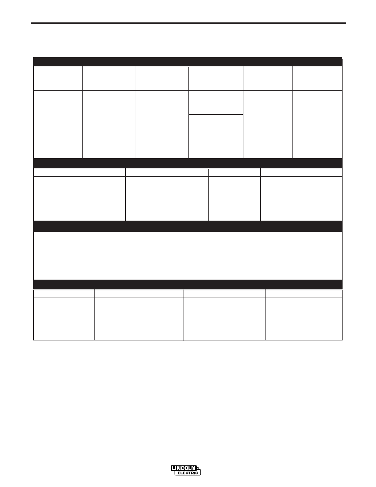
TECHNICAL SPECIFICATIONS - Ranger 300 D (K1522-1), Ranger 300 DLX (K1522-2)
INPUT - DIESEL ENGINE
Make/Model Description Speed (RPM) Displacement Starting Capacities
System
Kubota 3 cylinder High Idle 3700 54.9 cu. in
DH905 26.0 HP @ Low Idle 2150 (898 cc) (Group 45, 495 38 L
Diesel Engine 3600 RPM Full Load 3600 cold crank amps)
Bore x Stroke
2.83” x 2.90” w/ built in reg.
(72 mm x 73.6mm) Coolant: 5.7 qts.
12VDC battery
1 KW
Starter Oil: 5.4 Qts.
30 A. Alternator 5.1 L
Fuel: 10 gal.
RATED OUTPUT - WELDER
Welding Output Volts at Rated Amps Duty Cycle Max. OCV @ 3700 RPM
DC Constant Current 300 amps
AC Constant Current 300 amps
DC Constant Voltage (300 D) 200 amps
DC Constant Voltage (300 DLX) 300 amps
DC Constant Voltage (300 DLX) 280 amps
25 volts 100%
25 volts 100%
20 volts 100%
30 volts 60%*
30 volts 100%
80 volts RMS
OUTPUT - GENERATOR
Auxiliary Power
12,000 Watts, 60 Hz
120/240 Volts
100 % Duty Cycle
1
5.4 L
PHYSICAL DIMENSIONS
HEIGHT WIDTH DEPTH WEIGHT
37.38 in. 24.75 in. 60.50 in. 1093 lbs. (300 D)
1133 lbs. (300 DLX)
949.4 mm 628.7 mm 1528.6 mm 480.8 kg. (300 D)
499.0 kg. (300 DLX)
* Duty cycle is based on a 10 minute period. The machine can be loaded to 300 amps for 6 minutes out of every 10 minute
period.
1. Output rating in watts is equivalent to volt-amperes at unity power factor. Output voltage is within ± 10% at all loads up to
rated capacity. When welding, available auxiliary power will be reduced.
RANGER 300 D AND 300 DLX
A-2
INSTALLATION
A-2
SAFETY PRECAUTIONS
WARNING
Do not attempt to use this equipment until you
have thoroughly read the engine manufacturer’s
manual supplied with your welder. It includes
important safety precautions, detailed engine
starting, operating and maintenance instructions,
and parts lists.
------------------------------------------------------------------------
ELECTRIC SHOCK can kill.
• Do not touch electrically live parts or
electrode with skin or wet clothing.
• Insulate yourself from work and
ground
• Always wear dry insulating gloves.
------------------------------------------------------------------------
ENGINE EXHAUST can kill.
• Use in open, well ventilated areas or
vent exhaust outside.
------------------------------------------------------------------------
MOVING PARTS can injure.
• Do not operate with doors open or
guards off.
• Stop engine before servicing.
• Keep away from moving parts.
------------------------------------------------------------------------
See additional warning information at
front of this operator’s manual.
-----------------------------------------------------------
CAUTION
DO NOT MOUNT OVER COMBUSTIBLE SURFACES.
Where there is a combustible surface directly under
stationary or fixed electrical equipment, the surface
shall be covered with a steel plate at least
.06”(1.6mm) thick, which shall extend not more than
5.90”(150mm) beyond the equipment on all sides.
STORING
1. Store the machine in a cool, dry place when it is not
in use. Protect it from dust and dirt. Keep it where
it can’t be accidentally damaged from construction
activities, moving vehicles, and other hazards.
2. Drain the engine oil and refill with fresh 10W30 oil.
Run the engine for about five minutes to circulate
oil to all the parts. See the MAINTENANCE section
of this manual for details on changing oil.
3. If you are storing the machine for more than 30
days, drain the coolant from the radiator. Open the
cock at the bottom of the radiator and remove the
pressure cap so that the coolant drains completely.
Attach a note that says “NO WATER” on the radiator.
4. Remove the battery, recharge it, and adjust the
electrolyte level. Store the battery in a dry, dark
place.
Only qualified personnel should install,
use, or service this equipment.
LOCATION AND VENTILATION
Whenever you use the RANGER 300, be sure that
clean cooling air can flow through the machine’s
diesel engine and the machine case. Avoid dusty,
dirty areas. Also, keep the machine away from heat
sources. Do not place the engine end of the machine
anywhere near hot engine exhaust from another
machine or closer than two feet from a wall. And of
course, make sure that engine exhaust is ventilated to
an open, outside area.
The RANGER 300 may be used outdoors. Do not set
the machine in puddles or otherwise submerge it in
water. Such practices pose safety hazards and cause
improper operation and corrosion of parts.
Always operate the RANGER 300 with the case roof
on and all machine components completely assembled. This will protect you from the dangers of moving
parts, hot metal surfaces, and live electrical devices.
5. If the engine is not used for a long period of time,
every two to three months fill the radiator and run
the engine for about five minutes to keep it free
from rust.
STACKING
RANGER 300 machines CANNOT be stacked.
TILTING
Place the machine on a secure, level surface whenever you use it or store it. Any surfaces you place it on
other than the ground must be firm, non-skid, and
structurally sound.
The diesel engine is designed to run in a level position
for best performance. It can operate at an angle, but
this should never be more than 20 degrees in any
direction. If you do operate it at a slight angle, be sure
to check the oil regularly and keep the oil level at the
FULL mark as it would be in its normal level condition.
Also, fuel capacity will be a little less at an angle.
RANGER 300 D AND 300 DLX
A-3
INSTALLATION
A-3
HIGH ALTITUDE OPERATION
It may be necessary to de-rate the welder output at
higher altitudes. Derate the welder output 0.4% for
every 100 ft. (30 m) above 500 ft. (150 m). Some
engine adjustment may be required above 5,000 ft.
(1,500 m). Contact a Kubota Service Representative.
LIFTING
The RANGER 300 weighs approximately 1150
lbs/522 kg. A lift bail is mounted to the machine frame
and should always be used when lifting the machine.
ADDITIONAL SAFETY PRECAUTIONS
WARNING
FALLING EQUIPMENT can cause
injury.
● Do not lift this machine using lift
bale if it is equipped with a heavy
accessory such as trailer or gas
cylinder.
● Lift only with equipment of adequate lifting
capacity.
● Be sure machine is stable when lifting.
4. Typical conditions of use, i.e., travel speed; rough-
ness of surface on which the undercarriage will be
operated; environmental conditions; likely maintenance.
5. Conformance with federal, state and local laws.
(1)
Consult applicable federal, state and local laws regarding
specific requirements for use on public highways.
(1)
PRE-OPERATION ENGINE SERVICE
CAUTION
READ and UNDERSTAND the engine operating and
maintenance instructions supplied with this machine.
------------------------------------------------------------------------
WARNING
• Keep hands way from the engine muffler or HOT
engine parts.
• Stop the engine when fueling.
• Do not smoke when fueling.
• Do not overfill the fuel tank.
The recommended undercarriage for use with this
equipment for in-plant and yard towing by a vehicle is
Lincoln’s K953-1. If the user adapts a non-Lincoln
undercarriage, he must assume responsibility that the
method of attachment and usage does not result in a
safety hazard nor damage the welding equipment.
Some of the factors to be considered are as follows:
1. Design capacity of undercarriage vs. weight of
Lincoln equipment and likely additional attachments.
2. Proper support of, and attachment to, the base of
the welding equipment so there will be no undue
stress to the framework.
3. Proper placement of the equipment on the undercarriage to insure stability side to side and front to
back when being moved and when standing by
itself while being operated or serviced.
• Wipe up spilled fuel and allow the fumes to clear
before starting the engine.
• Keep sparks and flame away from the fuel tank.
------------------------------------------------------------------------
OIL
The RANGER 300 is shipped with the engine filled
with SAE 10W-30 oil. CHECK THE OIL LEVEL
BEFORE YOU START THE ENGINE. If it is not full,
add enough oil to fill it to the full mark.
Always use oil that is rated for diesel engine service
(API classification of CD/CE).
For more information on oil viscosity and service conditions, see the MAINTENANCE section of this manual and the engine Operator’s Manual.
RANGER 300 D AND 300 DLX
A-4
INSTALLATION
A-4
FUEL
Fill the fuel tank with clean No. 2, diesel fuel only. Do
not fill to the top of the filler neck to allow room for
expansion.
The RANGER 300 has a 10 gallon (38 liter) fuel tank
with a top fill and fuel gauge mounted on the control
panel. See the OPERATION and MAINTENANCE
sections of this manual for more details about fuel.
ENGINE COOLANT
WARNING
HOT COOLANT
• Do not remove cap if radiator is hot.
------------------------------------------------------------------------
The welder is shipped with the engine and radiator
filled with a 50% mixture of ethylene glycol and water.
The recovery bottle should be partially filled. See the
MAINTENANCE section and the engine Operator’s
Manual for more information on coolant.
can burn skin.
IMPORTANT: To prevent ELECTRICAL DAMAGE
WHEN:
a) Installing new batteries.
b) Using a booster.
Use correct polarity — Negative Ground.
The RANGER 300 is shipped with the negative battery cable disconnected. Before you operate the
machine, make sure the Engine Switch is in the OFF
position and attach the disconnected cable securely to
the negative (-) battery terminal.
Remove the insulating cap from the negative battery
terminal. Replace and tighten negative battery cable
terminal. NOTE: This machine is furnished with a wet
charged battery; if unused for several months, the battery may require a booster charge. Be sure to use the
correct polarity when charging the battery.
EXHAUST DEFLECTOR
CAUTION
Shut off the machine and allow the muffler to cool
before touching the muffler.
------------------------------------------------------------------------
BATTERY CONNECTIONS
WARNING
GASES FROM BATTERY can explode.
● Keep sparks, flame and cigarettes
away from battery.
To prevent EXPLOSION when:
● INSTALLING A NEW BATTERY — disconnect
negative cable from old battery first and connect
to new battery last.
● CONNECTING A BATTERY CHARGER —
remove battery from welder by disconnecting negative cable first, then positive cable and battery
clamp. When reinstalling, connect
negative cable last. Keep well ventilated.
● USING A BOOSTER — connect positive lead to
battery first then connect negative lead to negative
battery lead at engine foot.
● BATTERY ACID can burn eyes and
skin.
● Wear gloves and eye protection and
be careful when working near battery.
● Follow instructions printed on battery.
------------------------------------------------------------------------
The RANGER 300 is shipped with the exhaust deflector detached. Install it on the muffler outlet using the
clamp supplied. Rotate the deflector to the desired
direction before tightening the clamp.
SPARK ARRESTER
Diesel engine mufflers may emit sparks when the
engine is running. Some federal, state, or local laws
require spark arresters in locations where unarrested
sparks could present a fire hazard.
Standard muffler and deflectors (like the ones included with the RANGER 300 do not act as spark
arresters. When local laws require it, a spark arrester
must be installed on the machine and properly maintained. An optional spark arrester kit (K903-1) is
available for your RANGER 300. See the
ACCESSORIES section of this manual for more information.
CAUTION
An incorrect spark arrester may lead to damage to the
engine or reduce performance.
------------------------------------------------------------------------
RANGER 300 D AND 300 DLX
A-5
INSTALLATION
A-5
ELECTRICAL CONNECTIONS
See Figure B.1 in the OPERATION section of this
manual for location of the 115 and 230 volt receptacles, weld output terminals, circuit breakers and
ground stud.
MACHINE GROUNDING
Because the RANGER 300 creates its own power
from its diesel-engine driven generator, and if the
machine is not connected to premises wiring (home,
shop, etc.), you do not need to connect the machine
frame to an earth ground. However, for best protection against electrical shock, connect a heavy gauge
wire (#8 AWG or larger) from the ground stud located
on the bottom of the output panel (See Figure B.1) to
a suitable earth ground such as a metal pipe driven
into the ground.
WARNING
Do not ground the machine to a pipe that carries
explosive or combustible material.
------------------------------------------------------------------------
TOTAL COMBINED LENGTH OF
ELECTRODE AND WORK CABLES
Cable Length
0-50 Ft. (0-15 meters)
50-100 Ft. (15-39 meters)
100-150 Ft. (30-46 meters)
150-200 Ft. (46-61 meters)
200-250 Ft. (61-76 meters)
Cable Size for
300 Amps
100% Duty Cycle
1/0 AWG
1/0 AWG
2/0 AWG
2/0 AWG
3/0 AWG
Table A.1
CABLE INSTALLATION
Install the welding cables to your RANGER 300 as follows. See Figure B.1 for location of parts.
1. The diesel engine must be OFF to install welding
cables.
When the Ranger 300 is mounted on a truck or a trailer, the machine generator ground stud MUST be
securely connected to the metal frame of the vehicle.
See Figure B.1. The ground stud is marked with the
ground symbol.
If the RANGER 300 is connected to premises wiring
such as a home or shop, it must be properly connected to the system earth ground.
WELDING CABLE CONNECTIONS
CABLE SIZE AND LENGTH
Be sure to use welding cables that are large enough.
The correct size and length becomes especially
important when you are welding at a distance from the
welder.
Table A.1 lists recommended cable sizes and lengths
for rated current and duty cycle. Length refers to the
distance from the welder to the work and back to the
welder. Cable diameters are increased for long cable
lengths to reduce voltage drops.
2. Remove the flanged nuts from the output terminals.
3. Connect the electrode holder and work cables to
the weld output terminals. The terminals are identified on the case front.
4. Tighten the flanged nuts securely.
5. Be certain that the metal piece you are welding (the
“work”) is properly connected to the work clamp and
cable.
6. Check and tighten the connections periodically.
CAUTION
• Loose connections will cause the output terminals to
overheat. The terminals may eventually melt.
• Do not cross the welding cables at the output terminal connection. Keep the cables isolated and separate from one another.
------------------------------------------------------------------------
Lincoln Electric offers a welding accessory kit with the
properly specified welding cables. See the
ACCESSORIES section of this manual for more information.
RANGER 300 D AND 300 DLX

A-6
INSTALLATION
A-6
AUXILIARY POWER RECEPTACLES,
PLUGS, AND HAND-HELD EQUIPMENT
The control panel of the RANGER 300 features three
auxiliary power receptacles: See Figure B.1.
• Two 15 amp, 120 volt duplex (double outlet) receptacles.
• One 50 amp 120/240 volt simplex (single outlet)
receptacle.
Through these receptacles the machine can supply up
to 12,000 rated continuous watts of single-phase, 60
Hz AC power.
For further protection against electric shock, any electrical equipment connected to the generator receptacles must use a three-blade, grounded type plug or an
Underwriter’s Laboratories (UL) approved double
insulation system with a two-blade plug. Lincoln
offers an accessory plug kit that has the right type of
plugs. See the ACCESSORIES section of this manual
for more information.
If you need ground fault protection for hand-held
equipment refer to the K896-1 GFCI Receptacle kit in
the ACCESSORIES section of this manual for more
information.
CIRCUIT BREAKERS
PREMISES WIRING
The RANGER 300 is suitable for temporary, standby,
or emergency power using the engine manufacturer’s
recommended maintenance schedule. With its threewire grounded neutral generator, it can be permanently installed as a standby power unit for 240 volt, three
wire, single phase 50 ampere service.
WARNING
Only a licensed, certified, trained electrician should
install the machine to a premises or residential electrical system. Be certain that:
• The installation complies with the National Electrical
Code and all other applicable electrical codes.
• The premises is isolated and no feedbacking into
the utility system can occur. Certain state and local
laws require the premises to be isolated before the
generator is linked to the premises. Check your
state and local requirements.
• A double pole, double throw transfer switch in conjunction with the properly rated double throw circuit
breaker is connected between the generator power
and the utility meter.
------------------------------------------------------------------------
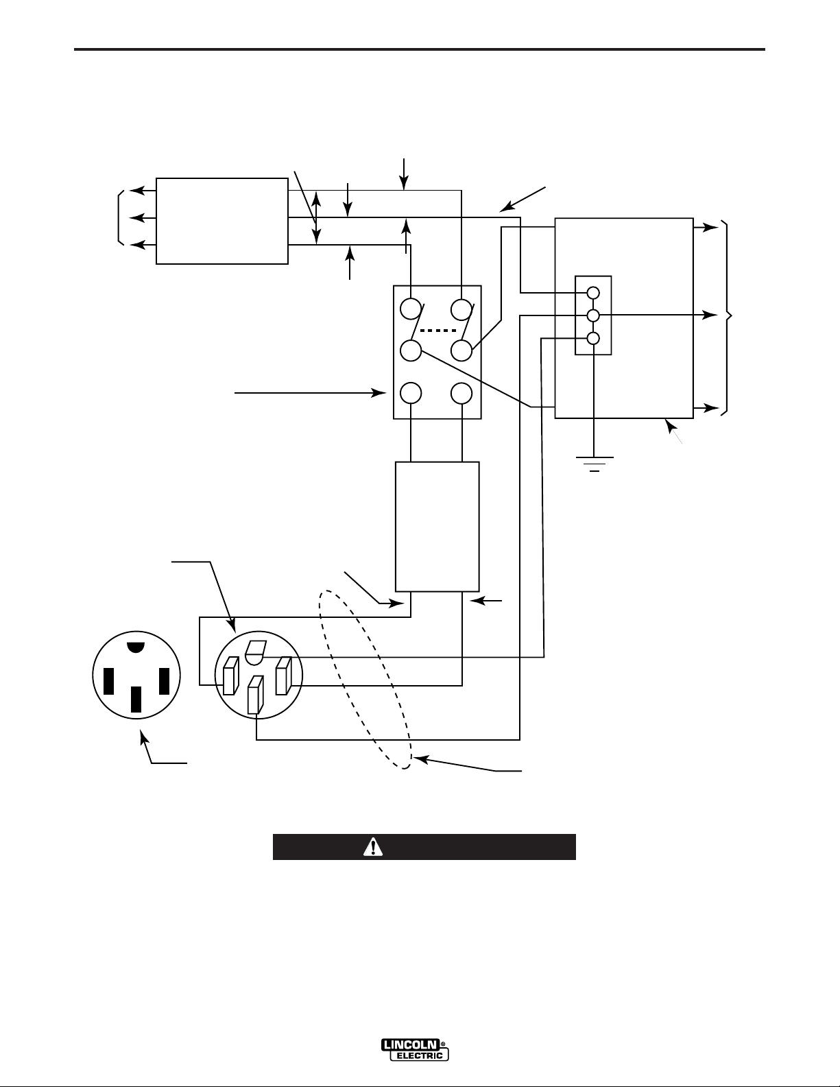
The following information and the connection diagram,
Figure A.1, can be used as a guide by the electrician
for most applications to premises wiring.
The RANGER 300 machines are equipped with 50
amp circuit breakers on the 120/240 V receptacle and
15 amp circuit breakers on the 120 receptacles for
overload protection. Under high heat a breaker may
tend to trip at lower loads than it would normally.
CAUTION
Never bypass the circuit breakers. Without overload
protection, the RANGER 300 D/DLX could overheat
and/or cause damage to the equipment being used.
------------------------------------------------------------------------
1. Install a double pole, double throw switch between
the power company meter and the premises disconnect. The switch rating must be the same as or
greater than the premises disconnect and service
overcurrent protection.
2. Take the necessary steps to assure that the load is
limited to the capacity of the RANGER 300 by
installing a 50 amp 240 volt double pole circuit
breaker. Maximum rated load for the 240 volt auxiliary is 50 amperes. Loading above 50 amperes will
reduce output voltage below the allowable -10% of
rated voltage. This may damage appliances or
other motor-driven equipment.
3. Install a 50 amp 120/240 volt plug (NEMA type 14-
50) to a double pole circuit breaker using No. 8 or
larger, 4 conductor cable of the desired length.
(The 50 amp 120/240 volt plug is available in the
optional power plug kit.
4. Plug this cable in to the 50 amp 120/240 volt receptacle on the RANGER 300 case front.
RANGER 300 D AND 300 DLX
A-7
240 Volt
60 Hz.
3-Wire
Service
POWER
COMPANY
METER
240 VOLT
120 VOLT
120 VOLT
LOAD
N
NEUTRAL
BUS
GROUND
PREMISES
DISCONNECT AND
SERVICE
OVERCURRENT
PROTECTION
GND
N
NOTE: No. 6 COPPER CONDUCTOR CABLE SEE
NATIONAL ELECTRICAL CODE FOR ALTERNATE WIRE
SIZE RECOMMENDATIONS.
240 VOLT
GROUNDED CONDUCTOR
50AMP
240 VOLT
DOUBLE
POLE
CIRCUIT
BREAKER
DOUBLE POLE DOUBLE THROW
SWITCH RATING TO BE THE SAME
AS OR GREATER THAN PREMISES
SERVICE OVERCURRENT
PROTECTION.
50 AMP, 120/240
VOLT PLUG
NEMA TYPE 14-50
50 AMP, 120/240 VOLT
RECEPTACLE
INSTALLATION
Figure A.1
CONNECTION OF RANGER 300 TO PREMISES WIRING
A-7
WARNING
Connection of Ranger 300 to premises wiring
must be done by a licensed electrician and must
comply with the National Electrical Code and all
other applicable electrical codes.
RANGER 300 D AND 300 DLX

B-1
OPERATION
B-1
GENERAL DESCRIPTION
The RANGER 300 is a diesel-engine driven, multiprocess AC and DC arc welder and AC power generator for commercial and residential applications. As a
generator it can supply up to 12,000 continuous watts
of 120/240 volt, 60 Hz, single-phase AC power to
operate AC power tools, battery chargers, and lighting; it can also be used to provide standby power. As
a welder it provides 300 amps of AC current for welding with AC stick electrodes or 300 amps of DC current for DC stick welding. The RANGER 300 can also
perform AC/DC TIG welding and DC semiautomatic
wire feed welding.
The engine used on the Ranger 300 machines is the
Kubota "Super Five" water-cooled, 3 cylinder DH905
engine. The DH905 has an offset piston design with
built in steel strut and a more rigid crank-case. The
Kubota "Three Vortex Combustion System" gives
higher power output, lower fuel consumption, lower
noise, and cleaner exhaust. The "Super Glow
System" gives rapid pre-heating for easy starting in
cold weather. The large oil sump adds to the long life
of this engine. The high capacity 30 amp alternator
gives fast charging of the 495 CCA battery. The
engine is extremely smooth and has very low vibration, even at low idle speed.
The Ranger 300 machines are housed in a heavy
gauge steel case that is protected by a durable powder paint finish. The case is completely insonorized for
remarkably quiet operation. An easy to open hinged
door allows access to the engine for single side service. The welder alternator has all copper windings
and a high temperature insulation system that
includes three coats of electrical grade varnish.
DESIGN FEATURES - ALL MODELS
FOR WELDING:
• Excellent AC and DC constant current output for
stick welding applications.
• 40 to 300 amps constant current output with seven
range settings.
• Excellent semi-automatic wire feed welding on constant voltage output range(s).
• TIG welding - full range on DC and up to 250 amps
on AC.
• 100% duty cycle rating on all output ranges.
• Remote control capability standard on all models.
Amphenol receptacle for easy connection of Lincoln
remote control accessories.
FOR AUXILIARY POWER:
• 12,000 watts of 120/240 volt 60Hz AC auxiliary
power.
• Power for tools, lights, electric pumps and for standby emergency power.
• Drive a 2 HP motor (provided it is started under no
load).
• Two 15 amp industrial grade 120 volt duplex receptacles for up to 60 amps of 120 volt power.
• One 50 amp 120/240 volt dual voltage receptacle for
up to 50 amps of 240 volt auxiliary power. Allows
easy connection to premises wiring.
• Four 15 amp circuit breakers for 120V duplex receptacles and 2-50 amp circuit breakers for 240V receptacle.
• Weld and have AC power at the same time (within
machine total capacity).
• Compatible with GFCI's (ground fault circuit interrupters).
OTHER FEATURES:
• Insonorized for extremely quiet operation (99LW(A)
and 74 db(A) @ 23 ft (7m)).
• Kubota 3-cylinder, liquid cooled, diesel engine.
Designed for long life, easy maintenance and excellent fuel economy and low noise.
• Engine always starts in low idle for minimum engine
wear in cold weather.
• Manual operated lift pump for easy priming of engine
if it runs out of fuel.
• Engine protection system shuts engine down on low
oil pressure or over temperature of coolant.
• Indicator lights for low oil pressure, over temperature
and battery charger low output.
• Engine Hour Meter standard on all models.
• Engine coolant recovery bottle eliminates air in radiator and makes it easy to check coolant level.
• Battery with 495 cold cranking amps.
• Straight through ventilation - cooling air for welder
alternator enters front of machine and is exhausted
out rear.
• Large capacity 10 gallon (38 l) fuel tank.
• Automatic idler reduces engine speed when not
welding or drawing auxiliary power. Machine always
starts in low idle. Reduces fuel consumption and
extends engine life.
• Compact size fits many smaller trucks.
• Single side engine service with easy to open access
door.
• Copper alternator windings and high temperature
insulation for dependability and long life.
• Powder painted case and base for outstanding corrosion protection.
RANGER 300 D AND 300 DLX

B-2
OPERATION
B-2
ADDITIONAL FEATURES
RANGER 300 D (K1522-1):
• One constant voltage wire-feed welding range - 80 to
200 amps.
The wire feed setting permits the Ranger 300D to be
used with the LN-25 Wire Feeder and .035, .045 or
.068 NR®-211-MP Innershield electrodes. Limited
MIG (GMAW) welding can also be done with .030 or
.035 L-50 & L-56 using blended Argon shielding gas.
“Auto-Idle” functions when using an LN-25 with an
internal contactor.
ADDITIONAL FEATURES
RANGER 300 DLX (K1522-2):
• Four constant voltage (CV) wire-feed welding
ranges with fine control on each range for welding at
40 to 300 amps.
• Excellent arc characteristics with MIG (GMAW) and
recommended Innershield electrodes (FCAW).
• Wire feeder amphenol receptacle (14 pin) for quick
connection of control cable.
• Voltmeter for reading CV wire-feed welding arc voltage.
• Built in contactor with front panel selection of "cold"
or "hot" welding terminals.
• Aluminum TIG welding when used with K930-1 TIG
Module. Output contactor control with Amptrol.
• Recommended wire feeders are the LN-25 with 42
Volt Remote Output Control Module or with internal
contactor and all models of the LN-7.
LIMITATIONS
• The Ranger 300 is not recommended for any
processes besides those that are normally performed using stick welding (SMAW), TIG welding
(GTAW), MIG (GMAW) welding and Innershield®
(FCAW) welding.
• The RANGER 300 D/DLX is not recommended
pipe thawing.
• During welding, generator power is limited and out-
put voltages can drop. Therefore, DO NOT OPER
ATE ANY SENSITIVE ELECTRICAL EQUIPMENT
WHILE YOU ARE WELDING. See Table B.4 for
permissible simultaneous welding and auxiliary
power loads.
for
ADDITIONAL SAFETY PRECAUTIONS
Always operate the welder with the roof and case
sides in place as this provides maximum protection
from moving parts and assures proper cooling air flow.
Read and understand all Safety Precautions before
operating this machine. Always follow these and any
other safety procedures included in this manual and in
the Engine Owner’s Manual.
Only qualified personnel should install, use, or service
this equipment.
-
RECOMMENDED APPLICA TIONS
WELDER
The RANGER 300 provides excellent constant current
AC/DC welding output for stick (SMAW) welding and
for TIG welding, and it offers constant voltage output
for DC semiautomatic wire feed welding.
GENERATOR
The RANGER 300 gives AC generator output for
medium use demands.
RANGER 300 D AND 300 DLX
CONTROLS AND SETTINGS
All generator/welder controls are located on the
Output Control Panel of the machine case front.
Diesel engine glow plug, idler control, and start/stop
controls are also on the case front. See Figure B.1
and the explanations that follow.
 Loading...