


Return to Master TOC |
View Safety Info |
Return to Master TOC |
View Safety Info |
Return to Master TOC |
View Safety Info |
Return to Master TOC |
View Safety Info |
RETURN TO MAIN MENU
SVM197-A
January, 2010
POWERARC® 5500
For use with machine code number: 11182, 11187, 11215, 11329, 11403, 11404, 11405
Safety Depends on You
Lincoln arc welding and |
cutting |
|
|
00 |
|
equipment is designed and built |
|
55 |
|||
|
|||||
|
|
|
|||
with safety in mind. However, |
|
|
|
||
your overall safety can be |
|
|
|
||
increased |
by proper installation |
|
|
|
|
. . . and thoughtful operation on |
|
|
|
||
your part. |
DO NOT INSTALL, |
|
|
|
|
OPERATE |
OR REPAIR |
THIS |
|
|
|
EQUIPMENT WITHOUT READ- |
|
|
|
||
ING THIS MANUAL AND THE |
|
|
|
||
SAFETY PRECAUTIONS CON- |
|
|
|
||
TAINED THROUGHOUT. |
And, |
|
|
|
|
most importantly, think before you act and be careful.
SERVICE MANUAL
Copyright © Lincoln Global Inc.
•World's Leader in Welding and Cutting Products •
•Sales and Service through Subsidiaries and Distributors Worldwide •
Cleveland, Ohio 44117-1199 U.S.A. TEL: 888.935.3877 FAX: 216.486.1751 WEB SITE: www.lincolnelectric.com
Return to Master TOC
Return to Master TOC
Return to Master TOC
Return to Master TOC
i SAFETY i
 WARNING
CALIFORNIA PROPOSITION 65 WARNINGS
Diesel engine exhaust and some of its constituents |
|
The engine exhaust from this product contains |
are known to the State of California to cause can- |
|
chemicals known to the State of California to cause |
cer, birth defects, and other reproductive harm. |
|
cancer, birth defects, or other reproductive harm. |
|
|
|
The Above For Diesel Engines |
|
The Above For Gasoline Engines |
ARC WELDING can be hazardous. PROTECT YOURSELF AND OTHERS FROM POSSIBLE SERIOUS INJURY OR DEATH. KEEP CHILDREN AWAY. PACEMAKER WEARERS SHOULD CONSULT WITH THEIR DOCTOR BEFORE OPERATING.
Read and understand the following safety highlights. For additional safety information, it is strongly recommended that you purchase a copy of “Safety in Welding & Cutting - ANSI Standard Z49.1” from the American Welding Society, P.O. Box 351040, Miami, Florida 33135 or CSA Standard W117.2-1974. A Free copy of “Arc Welding Safety” booklet E205 is available from the Lincoln Electric Company, 22801 St. Clair Avenue, Cleveland, Ohio 44117-1199.
BE SURE THAT ALL INSTALLATION, OPERATION, MAINTENANCE AND REPAIR PROCEDURES ARE PERFORMED ONLY BY QUALIFIED INDIVIDUALS.
FOR ENGINE powered equipment.
1.a. Turn the engine off before troubleshooting and maintenance work unless the maintenance work requires it to be running.
____________________________________________________
1.b.Operate engines in open, well-ventilated areas or vent the engine exhaust fumes
outdoors.
____________________________________________________
1.c. Do not add the fuel near an open flame welding arc or when the engine is running. Stop the engine and allow it to cool before refueling to prevent spilled fuel from vaporizing on contact with hot engine parts and igniting. Do not spill fuel when filling tank. If fuel is spilled, wipe it up and do not start engine until fumes have been eliminated.
____________________________________________________
1.d. Keep all equipment safety guards, covers and devices in position and in good repair.Keep hands, hair, clothing and tools away from V-belts, gears, fans and all other moving parts when starting, operating or repairing equipment.
____________________________________________________
1.e. In some cases it may be necessary to remove safety guards to perform required maintenance. Remove guards only when necessary and replace them when the maintenance requiring their removal is complete. Always use the greatest care when working near moving parts.
___________________________________________________
1.f. Do not put your hands near the engine fan. Do not attempt to override the governor or idler by pushing on the throttle control rods while the engine is running.
___________________________________________________
1.g. To prevent accidentally starting gasoline engines while turning the engine or welding generator during maintenance work, disconnect the spark plug wires, distributor cap or magneto wire as appropriate.
1.h. To avoid scalding, do not remove the radiator pressure cap when the engine is hot.
ELECTRIC AND MAGNETIC FIELDS may be dangerous
2.a. Electric current flowing through any conductor causes localized Electric and Magnetic Fields (EMF). Welding current creates EMF fields around welding cables and welding machines
2.b. EMF fields may interfere with some pacemakers, and welders having a pacemaker should consult their physician before welding.
2.c. Exposure to EMF fields in welding may have other health effects which are now not known.
2.d. All welders should use the following procedures in order to minimize exposure to EMF fields from the welding circuit:
2.d.1. Route the electrode and work cables together - Secure them with tape when possible.
2.d.2. Never coil the electrode lead around your body.
2.d.3. Do not place your body between the electrode and work cables. If the electrode cable is on your right side, the work cable should also be on your right side.
2.d.4. Connect the work cable to the workpiece as close as possible to the area being welded.
2.d.5. Do not work next to welding power source.
Mar ‘95
POWERARC® 5500

Return to Master TOC
Return to Master TOC
Return to Master TOC
Return to Master TOC
ii |
|
|
|
SAFETY |
|
ii |
|||||
|
|
|
|
|
|
|
|
||||
|
|
ELECTRIC SHOCK can kill. |
|
|
|
|
ARC RAYS can burn. |
||||
|
|
3.a. The electrode and work (or ground) circuits |
|
|
|
|
4.a. Use a shield with the proper filter and cover |
||||
|
|
are electrically “hot” when the welder is on. |
|
|
|
|
|||||
|
|
|
|
|
|
plates to protect your eyes from sparks and |
|||||
|
|
|
|
|
|
||||||
|
|
|
|
|
|
||||||
|
|
Do not touch these “hot” parts with your bare |
|
|
|
|
the rays of the arc when welding or observing |
||||
|
|
skin or wet clothing. Wear dry, hole-free |
|
|
|
|
open arc welding. Headshield and filter lens |
||||
|
|
gloves to insulate hands. |
|
|
|
|
should conform to ANSI Z87. I standards. |
||||
3.b. Insulate yourself from work and ground using dry insulation. |
|
4.b. Use suitable clothing made from durable flame-resistant |
|||||||||
|
Make certain the insulation is large enough to cover your full |
|
|
|
|
material to protect your skin and that of your helpers from |
|||||
|
area of physical contact with work and ground. |
|
|
|
|
the arc rays. |
|
|
|||
|
In addition to the normal safety precautions, if welding |
|
4.c. Protect other nearby personnel with suitable, non-flammable |
||||||||
|
must |
be performed |
under |
electrically hazardous |
|
|
|
|
screening and/or warn them not to watch the arc nor expose |
||
|
conditions (in damp locations or while wearing wet |
|
|
|
|
themselves to the arc rays or to hot spatter or metal. |
|||||
|
|
|
|
|
|
|
|
||||
|
clothing; on metal structures such as floors, gratings or |
|
|
|
|
|
|
|
|||
|
|
|
|
|
|
|
|||||
|
scaffolds; when in cramped positions such as sitting, |
|
|
|
|
|
|
|
|||
|
|
|
|
FUMES AND GASES |
|||||||
|
kneeling or lying, if there is a high risk of unavoidable or |
|
|
|
|
||||||
|
accidental contact with the workpiece or ground) use |
|
|
|
|
can be dangerous. |
|||||
|
the following equipment: |
|
|
|
|
|
|||||
|
• Semiautomatic DC Constant Voltage (Wire) Welder. |
|
|
|
|
5.a. Welding may |
produce |
fumes and gases |
|||
|
• DC Manual (Stick) Welder. |
|
|
|
|
|
hazardous to health. Avoid breathing these |
||||
|
|
|
|
|
|
||||||
|
• AC Welder with Reduced Voltage Control. |
|
|
|
|
fumes and gases.When welding, keep |
|||||
|
|
|
|
|
|
|
|
|
your head out of the fume. Use enough |
||
3.c. In semiautomatic or automatic wire welding, the electrode, |
|
|
|
|
ventilation and/or exhaust at the arc to keep |
||||||
|
electrode reel, welding head, nozzle or semiautomatic |
|
|
|
|
fumes and gases away from the breathing zone. When |
|||||
|
welding gun are also electrically “hot”. |
|
|
|
|
welding with electrodes which require special |
|||||
|
|
|
|
|
|
|
|
|
ventilation such as stainless or hard facing (see |
||
3.d. Always |
be sure the work cable makes a good electrical |
|
|
|
|
instructions on container or MSDS) or on lead or |
|||||
|
connection with the metal being welded. The connection |
|
|
|
|
cadmium plated steel and other metals or coatings |
|||||
|
should be as close as possible to the area being welded. |
|
|
|
|
which produce highly toxic fumes, keep exposure as |
|||||
|
|
|
|
|
|
|
|
|
low as possible and within applicable OSHA PEL and |
||
3.e. Ground the work or metal to be welded to a good electrical |
|
|
|
|
ACGIH TLV limits using local exhaust or mechanical ven- |
||||||
|
(earth) ground. |
|
|
|
|
|
|
tilation. In confined spaces or in some circumstances, |
|||
|
|
|
|
|
|
|
|
|
outdoors, a respirator may be required. Additional pre- |
||
3.f. |
Maintain the electrode holder, work clamp, welding cable and |
|
|
|
|
cautions are also required when welding on galvanized |
|||||
|
welding machine in good, safe operating condition. Replace |
|
|
|
|
steel. |
|
|
|||
|
damaged insulation. |
|
|
|
5. b. The operation of welding fume control equipment is affected |
||||||
|
|
|
|
|
|
||||||
3.g. Never dip the electrode in water for cooling. |
|
|
|
|
by various factors including proper use and positioning of the |
||||||
|
|
|
|
equipment, maintenance of the equipment and the specific |
|||||||
|
|
|
|
|
|
|
|
|
|||
3.h. Never |
simultaneously |
touch |
electrically “hot” parts of |
|
|
|
|
welding procedure and application involved. Worker expo- |
|||
|
|
|
|
sure level should be checked upon installation and periodi- |
|||||||
|
electrode holders connected to two welders because voltage |
|
|
|
|
||||||
|
|
|
|
|
cally thereafter to be certain it is within applicable OSHA PEL |
||||||
|
between the two can be the total of the open circuit voltage |
|
|
|
|
||||||
|
|
|
|
|
and ACGIH TLV limits. |
|
|
||||
|
of both welders. |
|
|
|
|
|
|
|
|
||
|
|
|
|
|
|
|
|
|
|
||
3.i. |
When working above floor level, use a safety belt to protect |
|
5.c. Do not weld in locations near chlorinated hydrocarbon vapors |
||||||||
|
|
|
|
coming from degreasing, cleaning or spraying operations. |
|||||||
|
yourself from a fall should you get a shock. |
|
|
|
|
||||||
|
|
|
|
|
The heat and rays of the arc can react with solvent vapors to |
||||||
|
|
|
|
|
|
|
|
|
|||
3.j. |
Also see Items 6.c. and 8. |
|
|
|
|
|
form phosgene, a highly toxic gas, and other irritating prod- |
||||
|
|
|
|
|
ucts. |
|
|
||||
|
|
|
|
|
|
|
|
|
|
|
|
|
|
|
|
|
|
5.d. Shielding gases used for arc welding can displace air and |
|||||
|
|
|
|
|
|
|
|
|
cause injury or death. Always use enough ventilation, |
||
|
|
|
|
|
|
|
|
|
especially in confined areas, to insure breathing air is safe. |
||
|
|
|
|
|
|
|
|
|
|||
|
|
|
|
|
|
5.e. Read and understand the manufacturer’s instructions for this |
|||||
|
|
|
|
|
|
|
|
|
equipment and the consumables to be used, including the |
||
|
|
|
|
|
|
|
|
|
material safety data sheet (MSDS) and follow your |
||
|
|
|
|
|
|
|
|
|
employer’s safety practices. MSDS forms are available from |
||
|
|
|
|
|
|
|
|
|
your welding distributor or |
from |
the manufacturer. |
|
|
|
|
|
|
5.f. Also see item 1.b. |
|
|
|||
|
|
|
|
|
|
|
|
|
|
|
|
Jan ‘09
POWERARC® 5500

Return to Master TOC
Return to Master TOC
Return to Master TOC
Return to Master TOC
iii |
|
|
|
|
|
SAFETY |
iii |
|
|
WELDING and CUTTING |
CYLINDER may explode |
||||||
|
SPARKS can |
|
|
|
if damaged. |
|
||
|
cause fire or explosion. |
7.a. Use only compressed gas |
cylinders |
|||||
|
6.a. Remove fire hazards from the welding area. |
containing the correct shielding gas for the |
||||||
|
|
If this is not possible, cover them to prevent |
process used and properly operating |
|||||
|
|
the welding sparks from starting a fire. |
regulators designed for the gas and |
|||||
|
Remember |
that |
welding |
sparks |
and |
hot |
pressure used. All hoses, fittings, etc. should be suitable for |
|
|
materials from welding can easily go through small cracks |
the application and maintained in good condition. |
|
|||||
|
and openings to adjacent areas. Avoid welding near |
|
|
|||||
|
hydraulic lines. Have a |
fire extinguisher readily available. |
7.b. Always keep cylinders in an upright position securely |
|||||
6.b. Where compressed gases are to be used at the job site, |
chained to an undercarriage or fixed support. |
|
||||||
|
|
|||||||
|
special precautions should be used to prevent hazardous |
7.c. Cylinders should be located: |
|
|||||
|
situations. Refer to “Safety in Welding and Cutting” (ANSI |
• Away from areas where they may be struck or subjected to |
||||||
|
Standard Z49.1) and the operating information for the |
physical damage. |
|
|||||
|
equipment being used. |
|
|
|
|
|
|
|
6.c. When not welding, make certain no part of the electrode |
• A safe distance from arc welding or cutting operations and |
|||||||
any other source of heat, sparks, or flame. |
|
|||||||
|
circuit is touching the work or ground. Accidental contact can |
|
|
|||||
|
cause overheating and create a fire hazard. |
|
|
7.d. Never allow the electrode, electrode holder or any other |
||||
6.d. Do not heat, cut or weld tanks, drums or containers until the |
electrically “hot” parts to touch a cylinder. |
|
||||||
|
|
|||||||
|
proper steps have been taken to insure that such procedures |
7.e. Keep your head and face away from the cylinder valve outlet |
||||||
|
will not cause flammable or toxic vapors from substances |
when opening the cylinder valve. |
|
|||||
|
inside. They can cause an explosion even though they have |
|
|
|||||
|
been “cleaned”. For information, purchase “Recommended |
7.f. Valve protection caps should always be in place and hand |
||||||
|
Safe Practices for the Preparation for Welding and Cutting of |
tight except when the cylinder is in use or connected for |
||||||
|
Containers and Piping That Have Held Hazardous |
use. |
|
|||||
|
Substances”, AWS F4.1 from the American Welding Society |
|
|
|||||
|
(see address above). |
|
|
|
|
7.g. Read and follow the instructions on compressed gas |
||
6.e. Vent hollow castings or containers before heating, cutting or |
cylinders, associated equipment, and CGA publication P-l, |
|||||||
“Precautions for Safe Handling of Compressed Gases in |
||||||||
|
welding. They may explode. |
|
|
|
Cylinders,” available from the Compressed Gas Association |
|||
6.f. |
Sparks and spatter are thrown from the welding arc. Wear oil |
1235 Jefferson Davis Highway, Arlington, VA 22202. |
||||||
|
|
|||||||
|
free protective garments such as leather gloves, heavy shirt, |
FOR ELECTRICALLY |
||||||
|
cuffless trousers, high shoes and a cap over your hair. Wear |
|||||||
|
ear plugs when welding out of position or in confined places. |
|||||||
|
powered equipment. |
|||||||
|
Always wear safety glasses with side shields when in a |
|||||||
|
welding area. |
|
|
|
|
|
|
|
6.g. Connect the work cable to the work as close to the welding |
8.a. Turn off input power using the disconnect |
|||||||
switch at the fuse box before working on |
||||||||
|
area as practical. Work cables connected to the building |
the equipment. |
|
|||||
|
framework or other locations away from the welding area |
|
|
|||||
|
increase the possibility of the welding current passing |
8.b. Install equipment in accordance with the U.S. National |
||||||
|
through lifting chains, crane cables or other alternate circuits. |
Electrical Code, all local codes and the manufacturer’s |
||||||
|
This can create fire hazards or overheat lifting chains or |
recommendations. |
|
|||||
|
cables until they fail. |
|
|
|
|
8.c. Ground the equipment in accordance with the U.S. National |
||
|
|
|
|
|
|
|
||
6.h. Also see item 1.c. |
|
|
|
|
Electrical Code and the manufacturer’s recommendations. |
|||
6.I. |
Read and follow NFPA 51B “ Standard for Fire Prevention |
|
|
|||||
|
During Welding, Cutting and Other Hot Work”, available from |
|
|
|||||
|
NFPA, 1 Batterymarch Park,PO box 9101, Quincy, Ma |
|
|
|||||
|
022690-9101. |
|
|
|
|
|
|
|
6.j. |
Do not use a welding power source for pipe thawing. |
|
|
|
||||
Refer to http://www.lincolnelectric.com/safety for additional safety information.
Jan ‘09
POWERARC® 5500

Return to Master TOC
Return to Master TOC
Return to Master TOC
Return to Master TOC
iv |
SAFETY |
iv |
PRÉCAUTIONS DE SÛRETÉ
Pour votre propre protection lire et observer toutes les instructions et les précautions de sûreté specifiques qui parraissent dans ce manuel aussi bien que les précautions de sûreté générales suivantes:
Sûreté Pour Soudage A L’Arc
1.Protegez-vous contre la secousse électrique:
a.Les circuits à l’électrode et à la piéce sont sous tension quand la machine à souder est en marche. Eviter toujours tout contact entre les parties sous tension et la peau nue ou les vétements mouillés. Porter des gants secs et sans trous pour isoler les mains.
b.Faire trés attention de bien s’isoler de la masse quand on soude dans des endroits humides, ou sur un plancher metallique ou des grilles metalliques, principalement dans
les positions assis ou couché pour lesquelles une grande partie du corps peut être en contact avec la masse.
c.Maintenir le porte-électrode, la pince de masse, le câble de soudage et la machine à souder en bon et sûr état defonctionnement.
d.Ne jamais plonger le porte-électrode dans l’eau pour le refroidir.
e.Ne jamais toucher simultanément les parties sous tension des porte-électrodes connectés à deux machines à souder parce que la tension entre les deux pinces peut être le total de la tension à vide des deux machines.
f.Si on utilise la machine à souder comme une source de courant pour soudage semi-automatique, ces precautions pour le porte-électrode s’applicuent aussi au pistolet de soudage.
2.Dans le cas de travail au dessus du niveau du sol, se protéger contre les chutes dans le cas ou on recoit un choc. Ne jamais enrouler le câble-électrode autour de n’importe quelle partie du corps.
3.Un coup d’arc peut être plus sévère qu’un coup de soliel, donc:
a.Utiliser un bon masque avec un verre filtrant approprié ainsi qu’un verre blanc afin de se protéger les yeux du rayonnement de l’arc et des projections quand on soude ou quand on regarde l’arc.
b.Porter des vêtements convenables afin de protéger la peau de soudeur et des aides contre le rayonnement de l‘arc.
c.Protéger l’autre personnel travaillant à proximité au soudage à l’aide d’écrans appropriés et non-inflammables.
4.Des gouttes de laitier en fusion sont émises de l’arc de soudage. Se protéger avec des vêtements de protection libres de l’huile, tels que les gants en cuir, chemise épaisse, pantalons sans revers, et chaussures montantes.
5.Toujours porter des lunettes de sécurité dans la zone de soudage. Utiliser des lunettes avec écrans lateraux dans les zones où l’on pique le laitier.
6.Eloigner les matériaux inflammables ou les recouvrir afin de prévenir tout risque d’incendie dû aux étincelles.
7.Quand on ne soude pas, poser la pince à une endroit isolé de la masse. Un court-circuit accidental peut provoquer un échauffement et un risque d’incendie.
8.S’assurer que la masse est connectée le plus prés possible de la zone de travail qu’il est pratique de le faire. Si on place la masse sur la charpente de la construction ou d’autres endroits éloignés de la zone de travail, on augmente le risque de voir passer le courant de soudage par les chaines de levage, câbles de grue, ou autres circuits. Cela peut provoquer des risques d’incendie ou d’echauffement des chaines et des câbles jusqu’à ce qu’ils se rompent.
9.Assurer une ventilation suffisante dans la zone de soudage. Ceci est particuliérement important pour le soudage de tôles galvanisées plombées, ou cadmiées ou tout autre métal qui produit des fumeés toxiques.
10.Ne pas souder en présence de vapeurs de chlore provenant d’opérations de dégraissage, nettoyage ou pistolage. La chaleur ou les rayons de l’arc peuvent réagir avec les vapeurs du solvant pour produire du phosgéne (gas fortement toxique) ou autres produits irritants.
11.Pour obtenir de plus amples renseignements sur la sûreté, voir le code “Code for safety in welding and cutting” CSA Standard W 117.2-1974.
PRÉCAUTIONS DE SÛRETÉ POUR LES MACHINES À SOUDER À TRANSFORMATEUR ET À REDRESSEUR
1.Relier à la terre le chassis du poste conformement au code de l’électricité et aux recommendations du fabricant. Le dispositif de montage ou la piece à souder doit être branché à une bonne mise à la terre.
2.Autant que possible, I’installation et l’entretien du poste seront effectués par un électricien qualifié.
3.Avant de faires des travaux à l’interieur de poste, la debrancher à l’interrupteur à la boite de fusibles.
4.Garder tous les couvercles et dispositifs de sûreté à leur place.
Mar ‘93
POWERARC® 5500

Return to Master TOC
Return to Master TOC
Return to Master TOC
Return to Master TOC
v |
SAFETY |
v |
Electromagnetic Compatibility (EMC)
Conformance
Products displaying the CE mark are in conformity with European Community Council Directive of 3 May 1989 on the approximation of the laws of the Member States relating to electromagnetic compatibility (89/336/EEC). It was manufactured in conformity with a national standard that implements a harmonized standard: EN 60974-10 Electromagnetic Compatibility (EMC) Product Standard for Arc Welding Equipment. It is for use with other Lincoln Electric equipment. It is designed for industrial and professional use.
Introduction
All electrical equipment generates small amounts of electromagnetic emission. Electrical emission may be transmitted through power lines or radiated through space, similar to a radio transmitter. When emissions are received by other equipment, electrical interference may result. Electrical emissions may affect many kinds of electrical equipment; other nearby welding equipment, radio and TV reception, numerical controlled machines, telephone systems, computers, etc. Be aware that interference may result and extra precautions may be required when a welding power source is used in a domestic establishment.
Installation and Use
The user is responsible for installing and using the welding equipment according to the manufacturer’s instructions. If electromagnetic disturbances are detected then it shall be the responsibility of the user of the welding equipment to resolve the situation with the technical assistance of the manufacturer. In some cases this remedial action may be as simple as earthing (grounding) the welding circuit, see Note. In other cases it could involve construction of an electromagnetic screen enclosing the power source and the work complete with associated input filters. In all cases electromagnetic disturbances must be reduced to the point where they are no longer troublesome.
Note: The welding circuit may or may not be earthed for safety reasons according to national codes. Changing the earthing arrangements should only be authorized by a person who is competent to access whether the changes will increase the risk of injury, e.g., by allowing parallel welding current return paths which may damage the earth circuits of other equipment.
Assessment of Area
Before installing welding equipment the user shall make an assessment of potential electromagnetic problems in the surrounding area. The following shall be taken into account:
a)other supply cables, control cables, signaling and telephone cables; above, below and adjacent to the welding equipment;
b)radio and television transmitters and receivers;
c)computer and other control equipment;
d)safety critical equipment, e.g., guarding of industrial equipment;
e)the health of the people around, e.g., the use of pacemakers and hearing aids;
f)equipment used for calibration or measurement
g)the immunity of other equipment in the environment. The user shall ensure that other equipment being used in the environment is compatible. This may require additional protection measures;
h)the time of day that welding or other activities are to be carried out.
L10093 3-1-96H
POWERARC® 5500

Return to Master TOC
Return to Master TOC
Return to Master TOC
Return to Master TOC
vi |
SAFETY |
vi |
Electromagnetic Compatibility (EMC)
The size of the surrounding area to be considered will depend on the structure of the building and other activities that are taking place. The surrounding area may extend beyond the boundaries of the premises.
Methods of Reducing Emissions
Mains Supply
Welding equipment should be connected to the mains supply according to the manufacturer’s recommendations. If interference occurs, it may be necessary to take additional precautions such as filtering of the mains supply. Consideration should be given to shielding the supply cable of permanently installed welding equipment, in metallic conduit or equivalent. Shielding should be electrically continuous throughout its length. The shielding should be connected to the welding power source so that good electrical contact is maintained between the conduit and the welding power source enclosure.
Maintenance of the Welding Equipment
The welding equipment should be routinely maintained according to the manufacturer’s recommendations. All access and service doors and covers should be closed and properly fastened when the welding equipment is in operation. The welding equipment should not be modified in any way except for those changes and adjustments covered in the manufacturers instructions. In particular, the spark gaps of arc striking and stabilizing devices should be adjusted and maintained according to the manufacturer’s recommendations.
Welding Cables
The welding cables should be kept as short as possible and should be positioned close together, running at or close to floor level.
Equipotential Bonding
Bonding of all metallic components in the welding installation and adjacent to it should be considered. However, metallic components bonded to the work piece will increase the risk that the operator could receive a shock by touching these metallic components and the electrode at the same time. The operator should be insulated from all such bonded metallic components.
Earthing of the Workpiece
Where the workpiece is not bonded to earth for electrical safety, not connected to earth because of its size and position, e.g., ships hull or building steelwork, a connection bonding the workpiece to earth may reduce emissions in some, but not all instances. Care should be taken to prevent the earthing of the workpiece increasing the risk of injury to users, or damage to other electrical equipment. Where necessary, the connection of the workpiece to earth should be made by a direct connection to the workpiece, but in some countries where direct connection is not permitted, the bonding should be achieved by suitable capacitance, selected according to national regulations.
Screening and Shielding
Selective screening and shielding of other cables and equipment in the surrounding area may alleviate problems of interference. Screening of the entire welding installation may be considered for special applica-
tions. 1
_________________________
1Portions of the preceding text are contained in EN 60974-10: “Electromagnetic Compatibility (EMC) product standard for arc welding equipment.”
L10093 3-1-96H
POWERARC® 5500

I |
- MASTER TABLE OF CONTENTS FOR ALL SECTIONS - |
I
RETURN TO MAIN MENU
Page
Safety . . . . . . . . . . . . . . . . . . . . . . . . . . . . . . . . . . . . . . . . . . . . . . . . . . . . . . . . . . . . . . . . . . . . . . . . . . .i-iv
Installation . . . . . . . . . . . . . . . . . . . . . . . . . . . . . . . . . . . . . . . . . . . . . . . . . . . . . . . . . . . . . . . . . .Section A
Operation . . . . . . . . . . . . . . . . . . . . . . . . . . . . . . . . . . . . . . . . . . . . . . . . . . . . . . . . . . . . . . . . . .Section B
Accessories . . . . . . . . . . . . . . . . . . . . . . . . . . . . . . . . . . . . . . . . . . . . . . . . . . . . . . . . . . . . . . . .Section C
Maintenance . . . . . . . . . . . . . . . . . . . . . . . . . . . . . . . . . . . . . . . . . . . . . . . . . . . . . . . . . . . . . . . .Section D
Theory of Operation . . . . . . . . . . . . . . . . . . . . . . . . . . . . . . . . . . . . . . . . . . . . . . . . . . . . . . . . . .Section E
Troubleshooting and Repair . . . . . . . . . . . . . . . . . . . . . . . . . . . . . . . . . . . . . . . . . . . . . . . . . . .Section F
Electrical Diagrams . . . . . . . . . . . . . . . . . . . . . . . . . . . . . . . . . . . . . . . . . . . . . . . . . . . . . . . . . .Section G
Parts Manual . . . . . . . . . . . . . . . . . . . . . . . . . . . . . . . . . . . . . . . . . . . . . . . . . . . . . . . . . . . . . . . . . . .P-510
POWERARC® 5500

Return to Master TOC
Return to Master TOC
Return to Master TOC
Return to Master TOC
A-1 |
TABLE OF CONTENTS - INSTALLATION SECTION |
A-1 |
Installation . . . . . . . . . . . . . . . . . . . . . . . . . . . . . . . . . . . . . . . . . . . . . . . . . . . . . . . . . . . . . . . . . . . . . . . . . . . . .A-1
Technical Specifications . . . . . . . . . . . . . . . . . . . . . . . . . . . . . . . . . . . . . . . . . . . . . . . . . . . . . . . . . . . . . . . .A-2 Safety Precautions . . . . . . . . . . . . . . . . . . . . . . . . . . . . . . . . . . . . . . . . . . . . . . . . . . . . . . . . . . . . . . . . . . . .A-3 Location . . . . . . . . . . . . . . . . . . . . . . . . . . . . . . . . . . . . . . . . . . . . . . . . . . . . . . . . . . . . . . . . . . . . . . . . . . . .A-3 Stacking, Tilting, Angle of Operation, Oil, Fuel . . . . . . . . . . . . . . . . . . . . . . . . . . . . . . . . . . . . . . . . . . . . . .A-4 Muffler, Spark Arrester . . . . . . . . . . . . . . . . . . . . . . . . . . . . . . . . . . . . . . . . . . . . . . . . . . . . . . . . . . . . . . . . .A-5 Component Locations, Output Connections . . . . . . . . . . . . . . . . . . . . . . . . . . . . . . . . . . . . . . . . . . . . . . . .A-6 Cable Installation, Machine Grounding . . . . . . . . . . . . . . . . . . . . . . . . . . . . . . . . . . . . . . . . . . . . . . . . . . . .A-7 Premises Wiring . . . . . . . . . . . . . . . . . . . . . . . . . . . . . . . . . . . . . . . . . . . . . . . . . . . . . . . . . . . . . . . . . . . . . .A-8 Electrical Device Use with the POWERARC® 5500 Table . . . . . . . . . . . . . . . . . . . . . . . . . . . . . . . . . . . . .A-9
POWERARC® 5500

Return to Section TOC |
Return to Master TOC |
Return to Section TOC |
Return to Master TOC |
Return to Section TOC |
Return to Master TOC |
Return to Section TOC |
Return to Master TOC |
A-2 |
|
|
|
INSTALLATION |
|
|
|
|
A-2 |
|||||
|
TECHNICAL SPECIFICATIONS - POWERARC® 5500 |
|
|
|
||||||||||
|
|
|
|
|
INPUT - GASOLINE ENGINE |
|
|
|
|
|
|
|||
|
Manufacturer |
Description |
|
Speed |
Displacement |
|
|
Ignition |
|
Capacities |
||||
|
Robin / Subaru |
1 cyl., |
|
3700 RPM |
|
16.17 cu. in. |
|
|
Manual, |
|
Fuel: 1.6 gal. (6.1 l) |
|||
|
EX 27 |
4 cycle |
|
± 50 RPM |
|
(265 cc) |
|
|
Recoil start; |
|
|
|
||
|
Codes |
air-cooled |
|
at no load |
|
|
|
Manual choke |
|
Oil: 1.1 qts.(1.0 l) |
||||
|
(11182, 11187) |
OHC gasoline |
|
|
|
|
|
|
|
|
|
|
|
|
|
(11329, 11403) |
9 HP @ |
|
|
|
|
|
|
|
|
|
|
|
|
|
(11405) |
3600 RPM |
|
|
|
|
|
|
|
|
|
|
|
|
|
|
|
INPUT |
- HONDA |
GASOLINE |
ENGINE |
|
|
|
|||||
|
|
|
|
|
|
|
|
|
|
|||||
|
|
|
INPUT |
- HONDA |
GASOLINE |
ENGINE |
|
|
|
|||||
|
Honda |
1 cyl., |
|
3700 RPM |
|
16.5 cu. in. |
|
|
Manual, |
|
Fuel: 1.6 gal. (6.1 l) |
|||
|
GX 270 VA2 |
4 cycle |
|
± 50 RPM |
|
(270 cc) |
|
|
Recoil start; |
|
|
|
||
|
Codes |
air-cooled OHV |
|
at no load |
|
|
|
Manual choke |
|
Oil: 1.2 qt. (1.1 l) |
||||
|
(11215) |
gasoline |
|
|
|
|
|
|
|
|
|
|
|
|
|
(11404) |
9 HP @ |
|
|
|
|
|
|
|
|
|
|
|
|
|
|
3600 RPM |
|
|
|
|
|
|
|
|
|
|
|
|
|
|
|
|
|
|
|
|
|
|
|
|
|
|
|
|
|
|
|
|
RATED OUTPUT - WELDER |
|
|
|
|
|
|
|||
|
Duty Cycle |
|
Amps AC |
|
Volts at Rated Amperes |
|||||||||
|
|
|||||||||||||
|
30% Duty Cycle |
|
125 Amps AC Constant Current |
|
|
|
20 VAC |
|||||||
|
60% Duty Cycle |
|
100 Amps AC Constant Current |
|
|
|
25 VAC |
|||||||
|
|
|
|
|
|
|
|
|
|
|
|
|
|
|
|
|
|
OUTPUT - WELDER AND GENERATOR |
|
|
|
||||||||
|
Welding Ranges |
|
Welder Open Circuit Voltage |
|
AC Auxiliary Power |
|||||||||
|
70 - 125 Amps AC |
|
62 VAC Max. |
|
4000 Continuous Watts |
|||||||||
|
|
|
|
|
|
|
|
|
|
|
5500 Surge Watts |
|||
|
|
|
|
|
PHYSICA |
|
|
|
|
|
|
|||
|
|
|
|
|
|
|
|
|
|
|
|
|
|
|
|
|
|
|
|
PHYSICAL DIMENSIONS |
|
|
|
|
|
|
|||
|
Height |
|
|
|
Width |
|
Depth |
|
|
|
|
Weight |
||
|
|
|
|
|
|
|
|
|
||||||
|
20.9 in. |
|
|
|
20 in. |
|
30 in. |
|
|
|
|
160 lb. |
||
|
530 mm |
|
|
|
508 mm |
|
762 mm |
|
|
|
|
72.5 kg |
||
|
|
|
|
|
|
|
|
|
|
|
|
|
|
|
|
|
|
|
|
|
|
|
|
|
|
|
|
|
|
POWERARC® 5500
Return to Section TOC |
Return to Master TOC |
Return to Section TOC |
Return to Master TOC |
Return to Section TOC |
Return to Master TOC |
Return to Section TOC |
Return to Master TOC |
A-3 |
INSTALLATION |
A-3 |
SAFETY PRECAUTIONS
Read this entire installation section before you start installation.
 WARNING
Do not attempt to use this equipment until you have thoroughly read all the operation and maintenance manuals supplied with your machine. They include important safety precautions; detailed engine starting, operating, and maintenance instructions; and parts lists.
ELECTRIC SHOCK can kill.
• Do not touch electrically live parts or electrodes with your skin or wet clothing.
• Insulate yourself from the work and ground.
•Always wear dry insulating gloves.
ENGINE EXHAUST can kill.
• Use in open, well ventilated areas or vent exhaust to the outside.
• Do not stack anything on or near the engine.
MOVING PARTS can injure.
• Do not operate this equipment with any of its doors open or guards off.
• Stop the engine before servicing it.
• Keep away from moving parts.
Only qualified personnel should install, use, or service this equipment.
LOCATION AND VENTILATION
Whenever you use the POWERARC® 5500, be sure that clean cooling air can flow through the machine’s gasoline engine and the generator. Avoid dusty, dirty areas. Also, keep the machine away from heat sources. Do not place the back end of the generator anywhere near hot engine exhaust from another machine. And of course, make sure that engine exhaust is ventilated to an open, outside area.
The POWERARC® 5500 must be used outdoors. Do not set the machine in puddles or otherwise submerge it in water. Such practices pose safety hazards and cause improper operation and corrosion of parts.
Always operate the POWERARC® 5500 with the case roof on and all machine components completely assembled. This will protect you from the dangers of moving parts, hot metal surfaces, and live electrical devices.
STORING
1.Store the machine in a cool, dry place when it’s not in use. Protect it from dust and dirt. Keep it where it can’t be accidentally damaged from construction activities, moving vehicles, and other hazards.
2.If you will be storing the machine for over 30 days, you should drain the fuel to protect fuel system and carburetor parts from gum deposits. Empty all fuel from the tank and run the engine until it stops from lack of fuel.
3.You can store the machine for up to 24 months if you use a gasoline stabilizing additive in the fuel system. Mix the additive with the fuel in the tank and run the engine for a short time to circulate the additive through the carburetor.
4.While the engine is still warm, drain the oil and refill with fresh oil per the engine manual.
5.Remove the spark plug and pour approximately 1/2 ounce (15 ml) of engine oil into the cylinder. Replace the spark plug and crank the engine slowly to distribute the oil.
6.Clean any dirt and debris from the cylinder and cylinder head fins and housing, rotating screen, and muffler areas.
7.Store in a clean, dry area.
POWERARC® 5500

Return to Section TOC |
Return to Master TOC |
Return to Section TOC |
Return to Master TOC |
Return to Section TOC |
Return to Master TOC |
Return to Section TOC |
Return to Master TOC |
A-4 |
INSTALLATION |
A-4 |
STACKING
POWERARC® 5500 machines CANNOT be stacked.
FUEL
TILTING
Fill the fuel tank with clean, fresh, regular grade lead-
Place the machine on a secure, level surface whenever you use it or store it. Any surfaces you place it on other than the ground must be firm, non-skid, and structurally sound.
The gasoline engine is designed to run in a level position for best performance. It can operate at an angle, but this should never be more than 15 degrees in any direction. If you do operate it at a slight angle, be sure to check the oil regularly and keep the oil level full. Also, fuel capacity will be a little less at an angle.
LIFTING
The POWERARC® 5500 should be lifted by two people. (It weighs 160 lbs/72.5 kg.) Its welded tube roll cage is designed to make lifting easy.
ANGLE OF OPERATION
Internal combustion engines are designed to run in a level condition to achieve optimum performance. The maximum angle of operation for the engine is 15 degrees from horizontal in any direction. Be certain to place the machine on a firm, non-skid, structural supporting surface. Anchor unit if necessary.
If you are operating the engine at a slight angle, be certain to check the oil regularly and maintain a level, full oil condition. The effective fuel capacity will also be slightly less than the specified 1.6 gallon (6.1 liters).
free gasoline. DO NOT MIX OIL WITH THE GASO-
LINE. Remove the fuel cap slowly to release pressure. Keep hands away from the engine muffler or HOT engine parts.
 WARNING
GASOLINE can cause fire or explosion.
•Stop engine while fueling.
•Do not smoke when fueling.
•Keep sparks and flame away from tank.
•Do not leave unattended while fueling.
•Wipe up spilled fuel and allow fumes to clear before starting engine.
•Do not overfill tank, fuel expansion may cause overflow.
GASOLINE FUEL ONLY
------------------------------------------------------------------------
The POWERARC® 5500 has a fuel tank mounted on the engine. See the engine owner’s manual for more details about fuel.
PRE-OPERATION ENGINE SERVICE
Read and understand the information about the gasoline engine in the OPERATION and MAINTENANCE sections of this manual and the engine owner’s manual before you operate the POWERARC® 5500.
OIL
The POWERARC® 5500 with the Robin / Subaru 9HP engine and the POWERARC® 5500 with the Honda 9 HP engine are supplied with low oil protection. Both engines are equipped with protection that will shut down the engine in the event of a low oil condition. The engine cannot be restarted until sufficient oil is added.
The POWERARC® 5500 is shipped with the engine filled with SAE 10W-30 oil. CHECK THE OIL LEVEL BEFORE YOU START THE ENGINE. This is an added precaution. When full, the oil level should be at the top of the fill plug hole. If it is not full, add enough oil to fill it. Be sure the fill plug is tight. Change oil after the first 20 hours of operation. For more oil fill and service information, see the Engine owner’s manual.
POWERARC® 5500

Return to Section TOC |
Return to Master TOC |
Return to Section TOC |
Return to Master TOC |
Return to Section TOC |
Return to Master TOC |
Return to Section TOC |
Return to Master TOC |
A-5 |
|
INSTALLATION |
A-5 |
||
|
|
PowerArc 5500 Typical Fuel Consumption |
|
||
|
|
|
|
|
|
|
|
|
Robin / Subaru 9 HP Carb. Certified |
|
Honda 9 HP |
|
|
|
EX 27 |
|
Carb. Certified |
|
|
|
|
|
|
|
No Load |
|
0.31 Gallons/Hour |
|
.30 Gallons/Hour |
|
3700 RPM ±50 R.P.M. |
|
(1.17 Liters/Hour) |
|
(1.14 Liters/Hour) |
|
AC CC Weld Output |
|
.70 Gallons/Hour |
|
.58 Gallons/Hour |
|
125 Amps @ 20 Volts |
|
(2.66 Liters/Hour) |
|
(2.18 Liters/Hour) |
|
AC CC Weld Output |
|
.66 Gallons/Hour |
|
.55 Gallons/Hour |
|
100 Amps @ 25 Volts |
|
(2.48 Liters/Hour) |
|
(2.1 Liters/Hour) |
|
Auxiliary Power 4000 |
|
.68 Gallons/Hour |
|
.67 Gallons/Hour |
|
Watts (120/240 Volts) |
|
(2.59 Liters/Hour) |
|
(2.54 Liters/Hour) |
|
|
|
|
|
|
MUFFLER DEFLECTOR
The POWERARC® 5500, Honda model, may or may not be shipped with an exhaust deflector. If you received one, you can mount it on the gasoline engine if your needs so require.
To install the deflector, do the following:
•Align the holes on the deflector plate with the holes on the muffler.
•Position the deflector so that the opening points either right, left, or downward, away from the operator.
 CAUTION
Never position the deflector upward. Moisture or debris can enter the engine and damage it. As a general safety practice, position the deflector to direct exhaust gases away from the operator’s face and eyes.
-----------------------------------------------------------
•Fasten the deflector onto the muffler with the screws provided.
NOTE: The deflector reduces generator output power up to 100 watts.
SPARK ARRESTER
Gasoline engine mufflers may emit sparks when the engine is running. Some federal, state, or local laws require spark arresters in locations where unarrested sparks could present a fire hazard.
The Robin / Subaru and Honda models of the POWERARC® 5500 come with a spark arrester as standard equipment. Refer to the engine owner’s manual for proper maintenance.
 CAUTION
An incorrect additional spark arrester may lead to damage to the engine or reduce performance.
-----------------------------------------------------------
POWERARC® 5500
Return to Section TOC |
Return to Master TOC |
Return to Section TOC |
Return to Master TOC |
Return to Section TOC |
Return to Master TOC |
Return to Section TOC |
Return to Master TOC |
A-6 |
INSTALLATION |
A-6 |
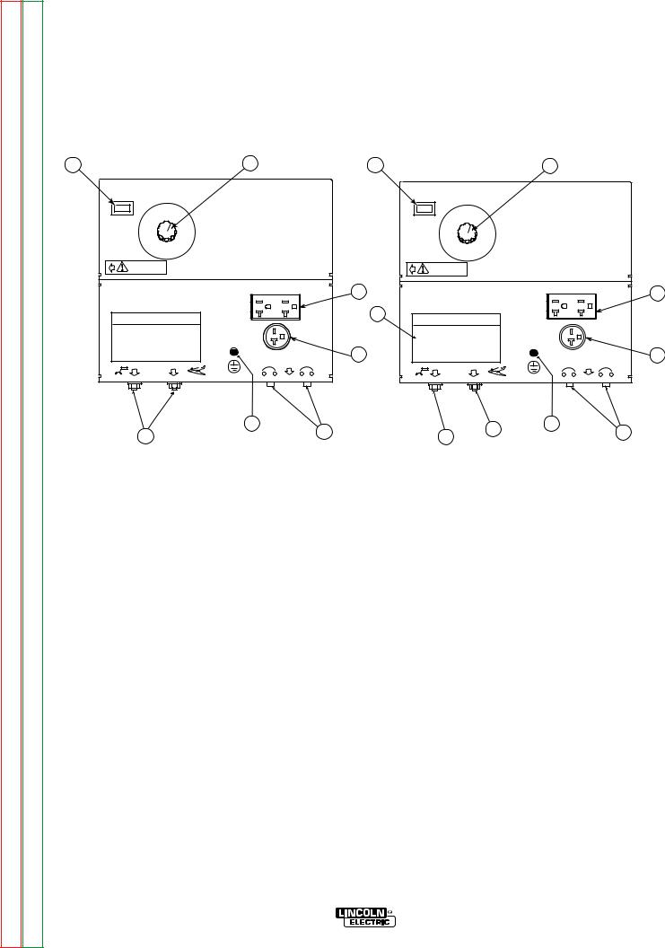
POWERARC® 5500 OUTPUT CONNECTIONS
Physical Location of Items and Components may vary by Code No.
FIGURE A.1 |
(For Codes 11182, 11187, 11215) |
|
FIGURE A.2 (For Codes 11403, 11404) |
||
7 |
|
1 |
9 |
|
1 |
70 |
80 |
POWERR ARCRC 5500 |
|
|
POWEER ARCRC 5500 |
AMPPS |
|
|
70 |
80 |
|
AMPSS |
|
|
|
AMPPS |
|
|
|
|
|
AMPSS |
|
12525 |
900 |
|
|
1255 |
|
AMPS |
|
|
90 |
||
AMPS |
|
|
AMPPS |
||
GENERATTOR |
|
|
AMPSS |
||
|
|
|
|
GENEERATORR |
|
|
1000 |
|
|
|
100 |
|
AMPS |
|
|
|
|
|
|
|
|
|
AMPSS |
WARNIARNINGG |
|
|
|
WARNRNINGG |
|
|
|
6 |
|
|
8 |
ELECECTRORODEE SELELECTTION GUIDUIDE |
|
2 |
ELEECTTRODEDE SELELECTICTION GUIDUIDE |
||
|
|
5 |
|
|
7 |
|
3 |
4 |
|
4 |
5 |
6 |
|
2 |
3 |
|
|||
|
|
|
|
|
||
1. |
CURRENT CONTROL DIAL |
|
1. |
CURRENT CONTROL DIAL |
|
|
2. |
WELD OUTPUT TERMINALS (2) |
|
2. |
WELD OUTPUT TERMINALS (2) |
|
|
3. |
GROUND STUD |
|
3. |
GROUND STUD |
|
|
4. |
CIRCUIT BREAKERS (2) - 20 AMP |
|
4. |
CIRCUIT BREAKER20 AMP |
|
|
5. |
RECEPTACLE - 240 VOLT, 20 AMP |
|
5. |
RECEPTACLE - 240 VOLT, 20 AMP |
|
|
6. |
DUPLEX RECEPTACLE - 120 VOLT, 20 AMP |
|
6. |
DUPLEX RECEPTACLE - 120 VOLT, 20 |
AMP |
|
7. |
TACHOMETER / HOUR METER |
|
7. |
TACHOMETER / HOUR METER |
|
|
|
(CODE 11215 ONLY) |
|
|
(CODE 11404 ONLY) |
|
|
ELECTRICAL OUTPUT
CONNECTIONS
See Figure A.1 for the location of the current control dial, weld output terminals, ground stud, circuit breakers, 240 and 120 volt receptacles.
WELDING CABLE CONNECTIONS
Cable Size and Length
Be sure to use welding cables that are large enough. The correct size and length becomes especially important when you are welding at a distance from the welder.
Table A.1 lists recommended cable sizes and lengths for rated current and duty cycle. Length refers to the distance from the welder to the work and back to the welder. Cable diameters are increased for long cable lengths to reduce voltage drops.
TABLE A.1
RECOMMENDED WELDING CABLE
SIZE AND LENGTH
TOTAL COMBINED LENGTH OF ELECTRODE AND
WORK CABLES
|
|
|
Cable Size for |
|
125 amp/ |
Cable Length |
30% Duty Cycle |
0-50 feet (0-15 meters) |
6 AWG |
50-100 feet (15-39 meters) |
4 AWG |
100-150 feet (30-46 meters) |
3 AWG |
150-200 feet (46-61 meters) |
2 AWG |
200-250 feet (61-76 meters) |
1 AWG |
|
|
POWERARC® 5500

Return to Section TOC |
Return to Master TOC |
Return to Section TOC |
Return to Master TOC |
Return to Section TOC |
Return to Master TOC |
Return to Section TOC |
Return to Master TOC |
A-7 |
INSTALLATION |
A-7 |
Cable Installation
Install the welding cables to your POWERARC® 5500 as follows. See Figure A.1 for the location of parts.
1.The gasoline engine must be OFF to install welding cables.
2.Remove the 1/2 - 13 flanged nuts from the output terminals.
3.Connect the electrode holder and work cables to the weld output terminals. You can connect either cable to either terminal, since the POWERARC® 5500 provides AC weld current.
4.Tighten the flanged nuts securely.
5.Be certain that the metal piece you are welding (the “work”) is securely connected to the work clamp and cable.
6.Check and tighten the connections periodically.
 CAUTION
•Loose connections will cause the output terminals to overheat. The terminals may eventually melt.
•Do not cross the welding cables at the output terminal connection. Keep the cables isolated and separate from one another.
Lincoln Electric offers a welding accessory kit with the properly specified welding cables. See the ACCESSORIES section of this manual for more information.
 WARNING
Do not ground the machine to a pipe that carries explosive or combustible material.
When the POWERARC® 5500 is mounted on a truck or a trailer, the machine generator ground
stud MUST be securely connected to the metal frame of the vehicle. See Figure
A.1. The ground stud is marked with the symbol.
PLUGS AND HAND-HELD EQUIPMENT
For further protection against electric shock, any electrical equipment connected to the generator receptacles must use a three-blade, grounded type plug or an Underwriter’s Laboratories (UL) approved double insulation system with a two-blade plug.
Ground fault protection is needed for hand held equipment.
 WARNING
Never operate this machine with damaged or defective cords. All electrical equipment must be in safe condition.
-------------------------------------------------------------
MACHINE GROUNDING
Because the POWERARC® 5500 creates its own power from its gasoline-engine driven generator, you do not need to connect the machine frame to an earth
ground. However, for best protection against electrical shock, connect a heavy gauge wire from the ground stud located on the bottom center of the output panel (see Figure A.1) to a suitable earth ground such as a metal pipe driven into the ground.
AUXILIARY POWER RECEPTACLES
The control panel of the POWERARC® 5500 features two auxiliary power receptacles:
•A 20 amp, 120 volt duplex (double outlet) receptacle
•A 20 amp 240 volt simplex (single outlet) receptacle.
See Figure A.1.
Through these receptacles the machine can supply up to 4,000 rated continuous watts and 5,500 surge watts of single-phase AC power.
POWERARC® 5500

Return to Section TOC |
Return to Master TOC |
Return to Section TOC |
Return to Master TOC |
Return to Section TOC |
Return to Master TOC |
Return to Section TOC |
Return to Master TOC |
A-8 |
INSTALLATION |
A-8 |
PREMISES WIRING
The POWERARC® 5500 three-wire, grounded neutral generator allows it to be connected to premises wiring. However, the wiring procedure needed to meet the National Electrical Code (NEC) regulations as well as city ordinances and can be confusing. The connections could vary from a "commonly grounded" to a "separately derived" system depending on whether you want the unit to be "hard wired" or temporary to the premises.
 WARNING
Only a licensed, certified, trained electrician should install the machine to a premises or residential electrical system. Be certain that:
•The premises is isolated and no feed backing into the utility system can occur. Certain state and local laws require the premises to be isolated before the generator is linked to the premises. Check your state and local requirements.
•A double pole, double throw transfer switch in conjunction with the properly rated double throw circuit breaker is connected between the generator power and the utility meter.
The POWERARC® 5500 does not have a combined 120/240 volt twist-lock receptacle and cannot be connected to a premises as described in other Lincoln literature.
Remember that the POWERARC® 5500 is intended only for backup, intermittent use power. Oil level must be checked after every 5 hours of use. It cannot withstand long-term use without proper maintenance. See the MAINTENANCE section of this manual and the engine owner’s manual for more information.
Certain electrical devices cannot be powered by the
POWERARC® 5500. Refer to Table A.2 for these devices.
CIRCUIT BREAKERS
Auxiliary power is protected by circuit breaker. When the machine is operated in high temperature environments, the breakers may tend to trip at lower loads than normally.
 CAUTION
Never bypass the circuit breakers. Without overload protection, the POWERARC® 5500 could overheat and/or cause damage to the equipment being used.
POWERARC® 5500

Return to Section TOC |
Return to Master TOC |
Return to Section TOC |
Return to Master TOC |
Return to Section TOC |
Return to Master TOC |
Return to Section TOC |
Return to Master TOC |
A-9 |
INSTALLATION |
A-9 |
 CAUTION
Certain Electrical devices cannot be powered by the POWERARC® 5500. See Table A.2.
TABLE A.2
ELECTRICAL DEVICE USE WITH THE POWERARC® 5500.
Type |
Common Electrical Devices |
Possible Concerns |
|
|
|
Resistive |
Heaters, toasters, incandescent |
NONE |
|
light bulbs, electric range, hot |
|
|
pan, skillet, coffee maker. |
|
|
|
|
Capacitive |
TV sets, radios, microwaves, |
Voltage spikes or high voltage |
|
appliances with electrical control. |
regulation can cause the capac- |
|
|
itative elements to fail. Surge |
|
|
protection, transient protection, |
|
|
and additional loading is recom- |
|
|
mended for 100% fail-safe |
|
|
operation. DO NOT RUN |
|
|
THESE DEVICES WITHOUT |
|
|
ADDITIONAL RESISTIVE TYPE |
|
|
LOADS. |
|
|
|
Inductive |
Single-phase induction motors, |
These devices require large |
|
drills, well pumps, grinders, small |
current inrush for starting. (See |
|
refrigerators, weed and hedge |
Table B.3, GENERATOR POWER |
|
trimmers |
APPLICATIONS, in the OPERA- |
|
|
TION section of this manual for |
|
|
required starting wattages.) |
|
|
Some synchronous motors may |
|
|
be frequency sensitive to attain |
|
|
maximum output torque, but |
|
|
they SHOULD BE SAFE from |
|
|
any frequency induced failures. |
|
|
|
Capacitive/Inductive |
Computers, high resolution TV sets, |
An inductive type line condition- |
|
complicated electrical equipment. |
er along with transient and |
|
|
surge protection is required, and |
|
|
liabilities still exist. DO NOT |
|
|
USE THESE DEVICES WITH A |
|
|
POWERARC® 5500. |
|
|
|
The Lincoln Electric Company is not responsible for any damage to electrical components improperly connected to the POWERARC® 5500.
POWERARC® 5500

Return to Section TOC |
Return to Section TOC |
Return to Section TOC |
Return to Section TOC |
|
|
|
|
Return to Master TOC |
Return to Master TOC |
Return to Master TOC |
Return to Master TOC |
|
|
|
|
|
|
|
10-A |
5500 POWERARC® |
NOTES |
10-A

Return to Master TOC
Return to Master TOC
Return to Master TOC
Return to Master TOC
B-1 |
TABLE OF CONTENTS - OPERATION SECTION |
B-1 |
Operation . . . . . . . . . . . . . . . . . . . . . . . . . . . . . . . . . . . . . . . . . . . . . . . . . . . . . . . . . . . . . . . . . . . . . . . . . . . . . .B-1
Safety Instructions . . . . . . . . . . . . . . . . . . . . . . . . . . . . . . . . . . . . . . . . . . . . . . . . . . . . . . . . . . . . . . . . . . . .B-2
Output Panel Controls . . . . . . . . . . . . . . . . . . . . . . . . . . . . . . . . . . . . . . . . . . . . . . . . . . . . . . . . . . . . . . . . .B-3
Gasoline Engine Controls, Engine Operation . . . . . . . . . . . . . . . . . . . . . . . . . . . . . . . . . . . . . . . . . . . . . . .B-4
Before Starting the Engine . . . . . . . . . . . . . . . . . . . . . . . . . . . . . . . . . . . . . . . . . . . . . . . . . . . . . . . . . . . . . .B-5
Stopping the Engine, Generator Operation . . . . . . . . . . . . . . . . . . . . . . . . . . . . . . . . . . . . . . . . . . . . . . . . .B-6
Generator Power Applications Table . . . . . . . . . . . . . . . . . . . . . . . . . . . . . . . . . . . . . . . . . . . . . . . . . . . . . .B-7
Welding Operation . . . . . . . . . . . . . . . . . . . . . . . . . . . . . . . . . . . . . . . . . . . . . . . . . . . . . . . . . . . . . . . . . . . .B-8
Welding Guidelines . . . . . . . . . . . . . . . . . . . . . . . . . . . . . . . . . . . . . . . . . . . . . . . . . . . . . . . . . . . . . . . . . . .B-9
What Happens in the Arc? . . . . . . . . . . . . . . . . . . . . . . . . . . . . . . . . . . . . . . . . . . . . . . . . . . . . . . . . .B-10/B-11
Practice, Metals . . . . . . . . . . . . . . . . . . . . . . . . . . . . . . . . . . . . . . . . . . . . . . . . . . . . . . . . . . . . . . . . . . . . .B-12
Types of Welds . . . . . . . . . . . . . . . . . . . . . . . . . . . . . . . . . . . . . . . . . . . . . . . . . . . . . . . . . . . . . . . . . .B-12/B16
Selecting Electrodes . . . . . . . . . . . . . . . . . . . . . . . . . . . . . . . . . . . . . . . . . . . . . . . . . . . . . . . . . . . . . . . . . .B-17
POWERARC® 5500

Return to Section TOC |
Return to Master TOC |
Return to Section TOC |
Return to Master TOC |
Return to Section TOC |
Return to Master TOC |
Return to Section TOC |
Return to Master TOC |
B-2 |
OPERATION |
B-2 |
SAFETY INSTRUCTIONS
Read and understand this entire section before operating your POWERARC® 5500.
WARNING
Do not attempt to use this equipment until you have thoroughly read all the operation and maintenance manuals supplied with your machine. They include important safety precautions; detailed engine starting, operating, and maintenance instructions; and parts lists.
ELECTRIC SHOCK can kill.
• Do not touch electrically live parts or electrodes with your skin or wet clothing.
•Insulate yourself from the work and ground.
•Always wear dry insulating gloves.
FUMES AND GASES can be dangerous.
• Keep your head out of fumes.
• Use ventilation or exhaust to remove fumes from breathing zone.
WELDING SPARKS can cause fire or explosion.


 • Keep flammable material away.
•Do not weld on containers that have held combustibles.
ARC RAYS can burn.
• Wear eye, ear, and body protection.
ENGINE EXHAUST can kill.
• Use in open, well ventilated areas or vent exhaust to the outside.
• Do not stack anything on or near the engine.
MOVING PARTS can injure.
• Do not operate this equipment with any of its doors open or guards off.
• Stop the engine before servicing it.
• Keep away from moving parts.
Only qualified personnel should install, use, or service this equipment.
GENERAL DESCRIPTION
The POWERARC® 5500 is a generator/welder designed for home use and other non-commercial applications. As a generator it can supply up to 4,000 continuous watts (or 5,500 surge watts) of 120/240 volt, single-phase AC power. As a welder it provides 125 amps of AC constant current for welding with AC stick electrodes. A single dial provides continuous adjustment of welding output. The machine is lightweight, portable, and can be lifted by two people.
The Lincoln warranty covers the POWERARC® 5500 (excluding the engine) for 3 years from the date of purchase. The engine is covered by the engine manufacturer’s warranty policy.
RECOMMENDED APPLICATIONS
GENERATOR
The POWERARC® 5500 gives AC generator output for medium use, non-commercial demands. For more details on operating the generator, see GENERATOR OPERATION in the OPERATION section of this manual.
WELDER
The POWERARC® 5500 provides excellent constant current AC welding output for stick (SMAW) welding. For more details on using the machine as a welder, see
WELDING OPERATION in the OPERATION section of this manual.
OPERATIONAL FEATURES AND CONTROLS
The POWERARC® 5500 was designed for simplicity. Therefore, it has very few operating controls. A single dial on the control panel lets you select either generator or welding use. For welding, the same dial selects continuous current output over the machine’s 70 to 125 amp range.
The gasoline engine controls include a recoil starter, choke, and rotary stop switch. See ENGINE OPERATION in the OPERATION section of this manual and the engine owner’s manual for details about starting, running, stopping, and breaking in the gasoline engine.
WELDING CAPABILITY
The POWERARC® 5500 is rated 125 amps, 20 volts at 30% duty cycle on a ten-minute basis. This means that you can load the welder to 125 amps for three minutes out of every ten-minute period. The machine is also capable of higher duty cycles at lower output currents. You can load the welder to 100 amps for six minutes out of ten for a 60% duty cycle.
The current is continuously variable from 70 to 125 amps AC. The POWERARC® 5500 can weld with all 3/32 and most 1/8 inch diameter Lincoln AC electrodes.
POWERARC® 5500
Return to Section TOC |
Return to Master TOC |
Return to Section TOC |
Return to Master TOC |
Return to Section TOC |
Return to Master TOC |
Return to Section TOC |
Return to Master TOC |
B-3 |
OPERATION |
B-3 |
OUTPUT PANEL CONTROLS
Physical Location of Components may vary by Code No.
FIGURE B.1 (For Codes 11182, 11187, 11215)
9 |
1 |
POWEER ARCRC 5500
70 |
80 |
AMPSPS |
|
AMMPSS |
|
1255 |
90 |
AMMPSS |
|
GENENERAATOR |
AMPMPS |
100
AMPSPS


 WARNIARNINGG
8
2
ELEECTRTRODE SELELECTIOTION GUIDUIDE
 7
7
|
4 |
5 |
3 |
6 |
|
|
|
1.CURRENT CONTROL DIAL
2.ELECTRODE SELECTION GUIDE
3.WELD OUTPUT TERMINAL (TO ELECTRODE HOLDER) WITH 1/2 - 13 FLANGE NUT
4.WELD OUTPUT TERMINAL (TO WORK) WITH 1/2 - 13 FLANGE NUT
5.GROUND STUD
6.20 AMP CIRCUIT BREAKERS (2)
7.20 AMP, 240 VOLT RECEPTACLE
8.20 AMP, 120 VOLT DUPLEX RECEPTACLE
9.TACHOMETER / HOUR METER (CODE 11215 ONLY)
FIGURE B.2 (For Codes 11403, 11404)
9 |
|
1 |
70 |
80 |
POWEER ARCRC 5500 |
AMPS |
|
|
AMPS |
|
|
125 |
90 |
8 |
AMPSS |
AMPSS |
|
GENERAATOOR |
100 |
|
|
|
|
|
AMPS |
|
WARNIARNINGG |
|
|
2 |
|
6 |
|
|
ELECTRORODE SELELECTIONN GUIDUIDE
7
3 |
4 |
5 |
1.CURRENT CONTROL DIAL
2.ELECTRODE SELECTION GUIDE
3.WELD OUTPUT TERMINAL (TO ELECTRODE HOLDER) WITH 1/2 - 13 FLANGE NUT
4.WELD OUTPUT TERMINAL (TO WORK) WITH 1/2 - 13 FLANGE NUT
5.GROUND STUD
6.20 AMP CIRCUIT BREAKER
7.20 AMP, 240 VOLT RECEPTACLE
8.20 AMP, 120 VOLT DUPLEX RECEPTACLE
9.TACHOMETER / HOUR METER (CODE 11404 ONLY)
LIMITATIONS
•The POWERARC® 5500 is not recommended for any processes besides those that are normally performed using stick welding (SMAW) procedures.
•The POWERARC® 5500 is not recommended for pipe thawing.
•During welding, generator power is limited to 100 watts, and output voltages can drop from 120 to 80 volts and 240 to 160 volts. Therefore, DO NOT OPERATE ANY SENSITIVE ELECTRICAL EQUIPMENT WHILE YOU ARE WELDING.
CONTROLS AND SETTINGS
All generator/welder controls are located on the Output Control Panel. Gasoline engine controls are mounted on the engine. See Figures B.1 and B.2 and the explanations that follow.
GENERATOR/WELDER CONTROLS
See Figure B.1 for the location of the following features:
1.CURRENT CONTROL DIAL: Adjusts continuous current output. The amperages on the dial correspond to the average amperages needed for specific Lincoln welding electrodes.
2.ELECTRODE SELECTION GUIDE: Provides recommended electrode type, size, and welder output setting based on the thickness of the work.
3.WELD OUTPUT TERMINAL (TO ELECTRODE
HOLDER) WITH 1/2 - 13 FLANGE NUT: Provides the connection point for either the electrode holder or the work cable. (Because the POWERARC® 5500 is an AC output machine, either output terminal can be used for either cable.)
POWERARC® 5500

Return to Section TOC |
Return to Master TOC |
Return to Section TOC |
Return to Master TOC |
Return to Section TOC |
Return to Master TOC |
Return to Section TOC |
Return to Master TOC |
B-4 |
OPERATION |
B-4 |
4.WELD OUTPUT TERMINAL (TO WORK) WITH 1/2
-13 FLANGE NUT: Provides the connection point for either the electrode holder or the work cable. (Because the POWERARC® 5500 is an AC output machine, either output terminal can be used for either cable.)
5.GROUND STUD: Provides a connection point for connecting the machine case to earth ground for the safest grounding procedure.
6.• 20 AMP CIRCUIT BREAKERS (2): Provide separate overload current protection for the 120 volt and 240 volt receptacles. (For codes 11182, 11187, 11215)
•20 AMP CIRCUIT BREAKER: Provide separate overload current protection for the 120 volt and 240 volt receptacles. (For codes 11403, 11404)
7.20 AMP, 240 VOLT RECEPTACLE: Connection point for supplying 240 volt power to operate one electrical device.
8.20 AMP, 120 VOLT DUPLEX RECEPTACLE: Connection point for supplying 120 volt power to operate one or two electrical devices.
9.Tachometer / Hour meter: (For Code 11215, 11404 Only)
Records engine speed in RPMs, engine running time, and alerts the user to perform a specific engine maintenance task by flashing corresponding messages. If the message reads “Chg Oil”, the user needs to change the oil in the engine. If the message reads “SVC AIR-FILTER”, the user needs to clean or if necessary,change the air filter. (See Honda Engine”s owners manual for more information). After maintenance task is preformed, the user is required to use the supplied Reset Tool to cancel flashing message and resume normal meter operation. (See MAINTENANCE SECTION for further details).
GASOLINE ENGINE CONTROLS
Refer to your engine manual for the location of the following features:
1.FUEL SHUTOFF VALVE: Stops the flow of gasoline from the fuel tank to the carburetor. Should be closed whenever you are finished using the POWERARC® 5500. Must be opened before you start the engine.
2.FUEL TANK AND CAP: See TECHNICAL SPECIFICATIONS for capacity.
NOTE: If you use any other alternate fuel tank or supply, be sure to use a recommended inline fuel filter.
3.MUFFLER: Reduces engine noise output. Both the Robin / Subaru and the Honda muffler serves as a spark arrester.
See SPARK ARRESTER in the INSTALLATION section of this manual.
4.“ON/OFF Switch: A two position switch located on the rear of the engine. In the “ON”(I) position, the engine ignition circuit is energized and the engine can be started by pulling the recoil rope starter. In the “OFF”(O) position, the electronic ignition is grounded and the engine shuts down.
5.AIR CLEANER: Filters intake air to the carburetor. See ENGINE MAINTENANCE in the MAINTENANCE section of the engine owner’s manual for details about the specific type of air cleaner to use.
6.CHOKE: Provides a richer air/fuel mix-
ture for cold engine starting conditions.
See the topic ENGINE OPERATION, below, for details on setting the choke.
7.RECOIL STARTER: Manual, rope-type starter. The handle position allows easy starting from either ground level or pickup-truck level
8.OIL DRAIN PLUG: Permits convenient draining of engine oil during maintenance. Both sides of the engine are equipped with an oil drain plug.
9.OIL FILL PLUG: Permits convenient filling of engine oil during maintenance. Both sides of the engine are equipped with an oil fill plug.
ENGINE OPERATION
 WARNING
DO NOT RUN THE ENGINE AT EXCESSIVE SPEEDS. The maximum allowable high idle speed for the POWERARC® 5500 is 3750 RPM, no load. Do NOT adjust the governor screw on the engine. Severe personal injury and damage to the machine can result if it is operated at speeds above the maximum rated speed.
-------------------------------------------------------------
Read and understand all safety instructions included in the engine manufacturer’s ”Operating and Maintenance Instructions” manual that is shipped with the POWERARC® 5500.
POWERARC® 5500

Return to Section TOC |
Return to Master TOC |
Return to Section TOC |
Return to Master TOC |
Return to Section TOC |
Return to Master TOC |
Return to Section TOC |
Return to Master TOC |
B-5 |
OPERATION |
B-5 |
BEFORE STARTING THE ENGINE
CHECK AND FILL THE ENGINE OIL LEVEL:
1. Place the machine on a level surface.
2.Open the oil fill plug.
3.Fill (if necessary) until oil flows out the top of the fill plug hole.
4.Replace the fill plug and tighten securely.
CHECK AND FILL THE ENGINE FUEL TANK:
1. Remove the fuel tank cap.
2. Fill the tank to allow approximately 1/4 inch (5 mm) of tank space for fuel expansion. DO NOT FILL THE TANK TO THE POINT OF OVERFLOW.
3. Replace the fuel tank cap and tighten securely.
NOTE: The engine will operate satisfactorily on any gasoline meant for automotive use. A minimum of 87 octane is recommended. DO NOT MIX OIL WITH THE GASOLINE.
Use clean, fresh, lead-free gasoline. Leaded gasoline may be used if lead-free is not available. However, lead-free gasoline leaves fewer combustion deposits and gives longer valve life. Purchase gasoline in quantities that will be used within 30 days, to assure freshness.
NOTE: We DO NOT recommend using gasoline that contains alcohol, such as gasohol. However, if gasoline with alcohol is used, it MUST NOT contain more than 10% Ethanol and MUST be removed from the engine during storage. DO NOT use gasoline containing Methanol.
STARTING THE ENGINE
NOTE: Remove all loads connected to the AC power receptacles before starting the gasoline engine. Put the “ON/OFF” Switch in the
“ON”(I) position.
FOR A “COLD” ENGINE:
1. Open the fuel shutoff valve.
2. Place the choke lever in the “CHOKE” position.
3.Pull slightly on the recoil starter handle until resistance is felt.
4.Pull the cord rapidly.
5.If the engine does not start, open the choke slightly and pull the starter cord rapidly again.
When the engine starts, gradually open the choke to the “RUN” position. To open the choke fully requires an engine warm-up period of several seconds to several minutes, depending on the temperature. After starting the engine, first open the choke (toward RUN) until the engine just begins to run smoothly. Then open the choke in small steps, allowing the engine to accept small changes in speed and load, until the choke is fully open (in RUN). During engine warm-up the equipment can be operated.
FOR A “HOT” ENGINE:
1.Open the fuel shutoff valve.
2.Place the choke lever in the “RUN”
position. Closing the choke of a hot engine will flood the carburetor and prevent starting.
3.Pull slightly on the recoil starter handle until resistance is felt.
4.Pull the cord rapidly.
FOR BEST ENGINE STARTING:
•Always use fresh gasoline and be sure the filter is clean and properly maintained.
•If you use an alternate fuel tank or supply, be sure to install an in-line fuel filter.
•Do not pull the recoil starter with the
choke in the “CHOKE” position more than one time. Repeated pulls on a choked engine will flood the carburetor.
•If the engine will not start, see the TROUBLESHOOTING section of this or the engine owner’s manual.
POWERARC® 5500

Return to Section TOC |
Return to Master TOC |
Return to Section TOC |
Return to Master TOC |
Return to Section TOC |
Return to Master TOC |
Return to Section TOC |
Return to Master TOC |
B-6 |
OPERATION |
B-6 |
STOPPING THE ENGINE
1.Remove all welding and generator power loads and let the engine cool by running it for several minutes.
2.Stop the engine by placing the “ON/OFF” switch in the “OFF”(O) position.
3.Close the fuel shutoff valve.
 WARNING
Close the fuel valve when the machine is transported to prevent fuel leakage from the carburetor. Drain the tank before transporting the machine in a vehicle.
For long periods of storage, turn off the fuel shutoff valve and let the engine run until there is no more fuel in the line. Use a fuel additive such as Sta-Bil to minimize fuel gum deposits.
-------------------------------------------------------------
GENERATOR OPERATION
 CAUTION
Be sure that any electrical equipment plugged into the generator’s AC power receptacles can withstand a ±10% voltage and a ±4% frequency variation. Some electronic devices cannot be powered by the POWERARC® 5500. Refer to Table A.2, ELECTRICAL DEVICE USE WITH THE POWERARC® 5500, in the INSTALLATION section of this manual.
-------------------------------------------------------------
GENERAL INFORMATION
The POWERARC® 5500 generator is rated at 4000 continuous watts (5500 surge watts). It provides both 120 volt and 240 volt power. You can draw up to 20 amps from either side of the 120 volt duplex receptacle, but no more than 33.3 amps from both sides at once. Up to 16.7 amps can be drawn from the single 240 volt receptacle.
RUNNING THE ENGINE
The engine is set at the factory to run at high idle speed when not under load. You should not adjust this setting yourself.
BREAK-IN PERIOD
The engine will use a greater amount of oil during its “break-in” period. Check the oil frequently during break-in. For more details, see the MAINTENANCE section in the engine owner’s manual.
 CAUTION
During break-in, subject the POWERARC® 5500 to only moderate loads. Avoid long periods running at idle. Before stopping the engine, remove all loads and allow the engine to cool several minutes.
-------------------------------------------------------------
Electrical loads in watts are calculated by multiplying the voltage rating of the load by the number of amps it draws. (This information is given on the load device nameplate.) For example, a device rated 120 volts, 2 amps will need 240 watts of power (120 x 2 = 240).
You can use Table B.3, GENERATOR POWER APPLICATIONS, to determine the wattage requirements of the most common types of loads you can power with the POWERARC® 5500. Be sure to read the notes at the bottom of the table.
TO USE THE POWERARC® 5500 AS AN AUXIL-
IARY POWER SUPPLY:
1.Start the gasoline engine. See ENGINE OPERA - TION in this section of the manual and the engine owner’s manual.
2.Set the current control dial on the output control panel to “GENERATOR.” See Figure B.1.
3.Plug the load(s) into the appropriate 120 volt or 240 volt power receptacle.
NOTE: During welding, the maximum generator output for auxiliary loads is 100 watts.
NOTE: You can supply multiple loads as long as the total load does not exceed 5,500 surge watts or 4,000 Continuous watts. Be sure to start the largest loads first.
POWERARC® 5500

Return to Section TOC |
Return to Master TOC |
Return to Section TOC |
Return to Master TOC |
Return to Section TOC |
Return to Master TOC |
Return to Section TOC |
Return to Master TOC |
B-7 |
OPERATION |
|
|
B-7 |
|||
|
|
|
TABLE B.3 |
|
|
|
|
|
|
GENERATOR POWER APPLICATIONS |
|
|
|
||
|
|
|
|
|
|
|
|
|
|
Suggested Power Applications |
|
Running Watts |
*Start-up Watts |
|
|
|
|
|
|
(Continuous) |
(Surge) |
|
|
|
|
|
|
|
|
|
|
|
|
*Air Compressor - 1 HP |
|
2,000 |
4,000 - 8,000 |
|
|
|
|
*Air Compressor - 3/4 HP |
|
1,250 |
3,100 - 5,000 |
|
|
|
|
*Airless Sprayer - 1/3 HP |
|
600 |
1,500 - 2,400 |
|
|
|
|
Chain Saw |
|
1,200 |
|
|
|
|
|
Circular Saw |
|
1,200 |
|
|
|
|
|
Coffee Maker |
|
1,000 |
|
|
|
|
|
*Deep Freezer |
|
500 |
750 - 2,000 |
|
|
|
|
*Electric Motor - 1 HP |
|
1,000 |
2,500 - 4,000 |
|
|
|
|
Electric Range (1 element) |
|
1,500 |
|
|
|
|
|
Electric Skillet |
|
1,250 |
|
|
|
|
|
*Furnace Fan - 1/3 HP |
|
1,200 |
3,000 - 4,800 |
|
|
|
|
Portable Grinder (4 1/2”) |
|
600 |
|
|
|
|
|
Portable Grinder (7”) |
|
2,000 |
|
|
|
|
|
Halogen Work Light |
|
500 |
|
|
|
|
|
Hand Drill - 1/4” |
|
500 |
|
|
|
|
|
Hand Drill - 3/8” |
|
700 |
|
|
|
|
|
1500 Watt Heater |
|
1,750 |
|
|
|
|
|
Hedge Trimmer |
|
450 |
|
|
|
|
|
Light Bulb |
|
100 |
|
|
|
|
|
Reciprocating Saw |
|
900 |
|
|
|
|
|
Radial Arm Saw |
|
2,600 |
|
|
|
|
|
Radio |
|
50 |
|
|
|
|
|
*Refrigerator/Freezer (small) |
|
600 |
1,500 - 2,400 |
|
|
|
|
Slow Cooker |
|
200 |
|
|
|
|
|
*Submersible Pump - 1 HP |
|
1,000 |
2,500 - 4,000 |
|
|
|
|
*Sump Pump |
|
600 |
1,500 - 2,400 |
|
|
|
|
Toaster |
|
1,100 |
|
|
|
|
|
Weed Trimmer |
|
500 |
|
|
|
|
|
Lincoln Wire Feeder/Welder |
|
4,000 |
|
|
|
|
|
|
|
|
|
|
|
NOTES:
Wattages listed are approximate. Check your equipment for actual wattage.
Equipment with unusually high *START-UP WATTS are listed. For start-up of other tabled equipment that uses a motor, allow up to 2 times the running watts shown above. For example a 1 HP motor requires approximately 1000 watts of power when running but may require (2.5 X 1000) = 2500 watts or (4.0 X 1000) = 4000 watts to start.
Multiple loads can be used as long as the total load does not exceed 5,500 surge watts or 4,000 continuous watts. Be certain to start the largest loads first.
Output rating in watts is equivalent to volt-amperes at unity power factor (resistive load) and is calculated as: WATTS = VOLTS X AMPS DRAWN. for example a 120 volt device which is rated on its nameplate to draw 2 amps will need (120 VOLTS) X (2 AMPS) = 240 WATTS OF POWER. 1 KW = 1000 WATTS.
POWERARC® 5500

Return to Section TOC |
Return to Master TOC |
Return to Section TOC |
Return to Master TOC |
Return to Section TOC |
Return to Master TOC |
Return to Section TOC |
Return to Master TOC |
B-8 |
OPERATION |
B-8 |
WELDING OPERATION
GENERAL INFORMATION
WARNING
ELECTRIC SHOCK can kill.
• Do not touch electrically live parts or electrodes with your skin or wet clothing.
•Insulate yourself from the work and ground.
•Always wear dry insulating gloves.
-------------------------------------------------------------
The POWERARC® 5500 has a voltage of up to 62
Volts AC which can shock. The POWERARC® 5500 generator/welder can deliver from 70 to 125 amps of continuous welding output current. Output can be adjusted by setting the current control dial on the output control panel.
You can get maximum welding output by setting the dial to 125 AMPS. At high current settings like this, some output may decrease as the machine is used. If you are welding for a long time, you may need to turn the dial slightly upward to maintain the same results.
The numbers on the dial correspond to the average amps needed to weld using specific Lincoln welding
rods. Table B.4, WELDING APPLICATIONS, gives you the recommended dial settings based on the thickness of the work and the size and type of rod you’re using.
TO USE THE POWERARC® 5500 FOR WELDING:
1.Remove the flange nuts from the weld output terminals and place the work and electrode welding cables over the terminals. (See Figure B.1) Replace and tighten the flange nuts securely. Be sure the connections are tight.
2.Select the appropriate electrode. (See Table B.4) WELDING APPLICATIONS, or the ELECTRODE SELECTION GUIDE on the machine Output Control Panel.
3.Attach the work clamp securely to the work you are welding.
4.Insert the electrode into the electrode holder.
5.Set the current control dial to the desired output current.
6.Start the gasoline engine. See ENGINE OPERATION in this section of the manual.
7.Strike an arc and begin welding. For information on welding techniques, see WELDING GUIDELINES in this section of the manual.
AFTER YOU FINISH THE WELD:
1.Stop the gasoline engine. See ENGINE OPERATION in this section of the manual.
2.Allow the electrode and work to cool completely.
3.Remove the work clamp from the work.
4.Remove any remaining piece of electrode from the electrode holder.
5.If you are finished using the POWERARC® 5500 for welding, disconnect the welding cables from the weld output terminals. Reattach the flange nuts and leave them on the terminals.
NOTE: 1. Welding current is continuously variable with 60% duty cycle applying to output currents 100 Amps and less and 30% duty cycle applying to currents above 100 Amps.
2. Duty cycle is based on a ten minute |
peri- |
od. The welder can be loaded to 125 |
|
Amps for three minutes out of every ten |
|
minute period or to 100 Amps for six |
min- |
utes out of every ten minute period. |
|
CONTROL FUNCTION / OPERATION “Current Control Dial”
Provides welding current adjustment from 70 through 125 Amps.
To obtain maximum weld output, turn the “Current Control Dial” to “125 Amps” for either a cold or hot engine. As the machine is used, some welding voltage may decrease at high current settings. If you are welding for long periods of time, the dial may need to be slightly turned upward to provide the same welding results as when the machine was cold.
The numbers listed on the dial correspond to the average amperage needed to weld specific Lincoln rods. Refer to Table B.4 “Welding Application Guides” and “Electrode Selection Guide” listed on the machine nameplate for proper current and electrode settings.
POWERARC® 5500

Return to Section TOC |
Return to Master TOC |
Return to Section TOC |
Return to Master TOC |
Return to Section TOC |
Return to Master TOC |
Return to Section TOC |
Return to Master TOC |
B-9 |
OPERATION |
|
|
B-9 |
|
WELDING GUIDELINES |
|
|
|
||
|
TABLE B.4 |
|
|
|
|
WELDING APPLICATIONS/ELECTRODE SELECTION GUIDE |
|
||||
|
|
|
|
|
|
Material Thickness |
Electrode Type |
|
Size |
|
Setting |
|
|
|
|
|
|
|
FLEETWELD® 37 |
|
|
|
90 amps |
|
1AWS E6013 |
|
|
|
|
1/8” and thinner |
FLEETWELD® 180 |
|
3/32” |
|
70 amps |
|
AWS E6011 |
|
|
|
|
|
Lincoln 7018 AC |
|
|
|
90 amps |
|
AWS E7018 |
|
|
|
|
|
|
|
|
|
|
3/16” Maximum |
FLEETWELD® 37 |
|
1/8” |
|
125 amps |
|
AWS E6013 |
|
|
|
|
|
|
|
|
|
|
5/16” Maximum |
FLEETWELD® 180 |
|
1/8” |
|
90 amps |
|
AWS E6011 |
|
|
|
|
|
|
|
|
|
|
Any Thickness |
WEARSHIELD® ABR |
|
1/8” |
|
100 amps |
|
|
|
|
|
|
NOTES:
The values listed are suggested settings. Actual setting may vary depending on individual preference and/or specific application. Beginners should use Lincoln E7018 AC.
For electrodes not listed, follow tables that are packed with the electrodes.
Ask for the Lincoln WELD DIRECTORY (Publication C2.10) for a complete listing of all Lincoln stick electrodes available.
1AWS = American Welding Society
WARNING
ARC RAYS can burn.
• When using an open arc process, it is necessary to use correct eye,
head and body protection.
------------------------------------------------------------------------
Stick Welding
Stick welding is probably the most familiar welding process known. A coated ELECTRODE, the weld rod, is clamped into an ELECTRODE HOLDER, an insulated clamping device, which in turn connects to the ELECTRODE CABLE, a heavy wire. The WORK, the metal piece to be welded, is connected to the WORK CABLE, a heavy wire which contains the WORK CLAMP. Quality Lincoln cables use many fine copper wires with a very flexible insulating covering for the electrode and work cables. When properly connected to the OUTPUT STUDS of a high current power source, the electrode melts and bonds the metal being repaired. See “Cable Installation” section for proper cable connection to a POWERARC®.
The POWERARC® provides excellent weld output characteristics when used in combination with Lincoln AC electrodes. Other AC electrodes may also be used.
Follow the settings listed in Table B.4 “Welding Application Guide” and the “Electrode Selection Guide” found on the nameplate of the machine.
Semi-automatic, Wire Welding With a
Lincoln Wire Feeder / Welder
The POWERARC® 5500 generator power can be used to supply power up to 4,000 watts continuous input power to a Lincoln Wire Feeder/Welder. The Wire Feeder/Welder is equipped with all the supplies needed for Flux-Cored Arc Welding (FCAW). Also some Wire Feeder/Welders come equipped with the essentials needed for Gas
Metal Arc Welding, GMAW, or MIG processes, while others require the purchase of a conversion kit. These products are available where Lincoln products are sold. Contact your local authorized Lincoln representative for more details.
Learning To Stick Weld
The serviceability of a product or structure utilizing this type of information is and must be the sole responsibility of the builder/user. Many variables beyond the control of The Lincoln Electric Company affect the results obtained in applying this type of information. These variables include, but are not limited to, welding procedure, plate chemistry and temperature, weldment design, fabrication methods and service requirements.
POWERARC® 5500
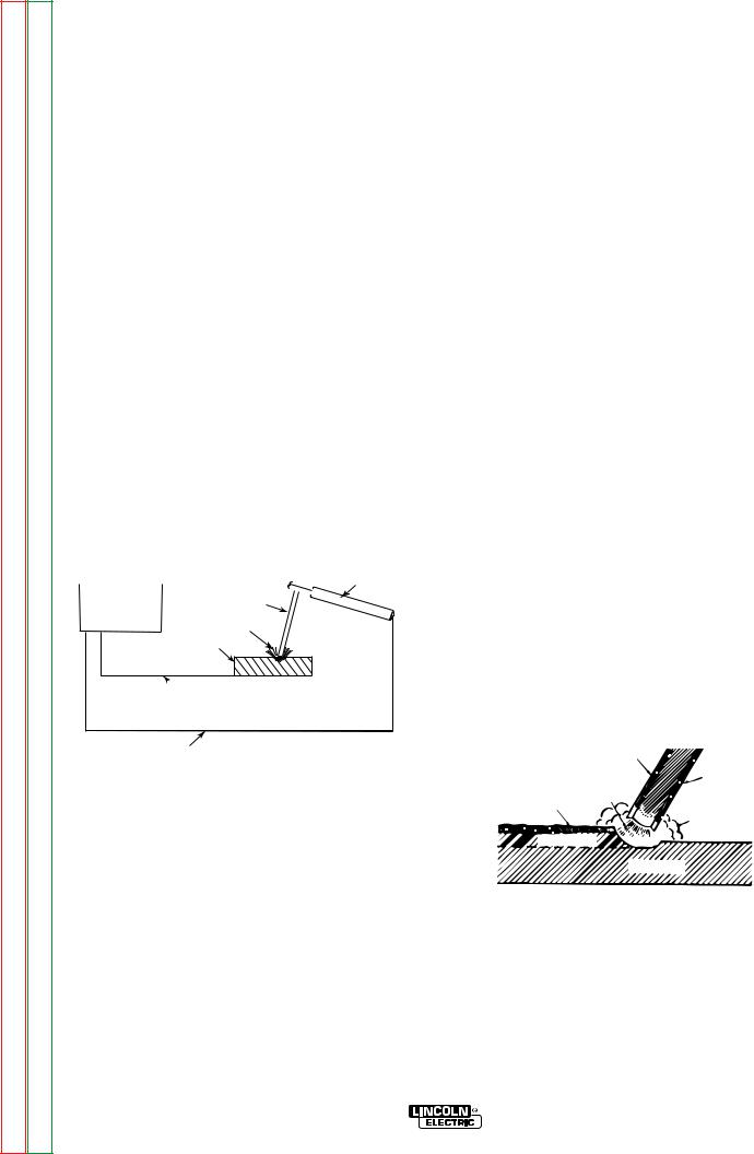
Return to Section TOC |
Return to Master TOC |
Return to Section TOC |
Return to Master TOC |
Return to Section TOC |
Return to Master TOC |
Return to Section TOC |
Return to Master TOC |
B-10 |
OPERATION |
B-10 |
No one can learn to weld simply by reading about it. Skill comes only with practice. The following pages will help the inexperienced welder understand welding and develop his skill. For more detailed information, order a copy of the book “New Lessons in Arc Welding.” (See Book Division section at rear of manual).
The operator’s knowledge of arc welding must go beyond the arc itself. He must know how to control the arc, and this requires a knowledge of the welding circuit and the equipment that provides the electric current used in the arc. Figure 3 is a diagram of the welding circuit. The circuit begins where the electrode cable is attached to the welding machine and ends where the work cable cable is attached to the machine. Current flows through the electrode cable to the electrode holder, through the electrode holder to the electrode and across the arc. On the work side of the arc, the current flows through base metal to the work cable and back to the welding machine. The circuit must be complete for the current to flow. To weld, the work clamp must be tightly connected to clean base metal. Remove paint, rust,etc. as necessary to get a good connection. Connect the work clamp as close as possible to the area you wish to weld. Avoid allowing the welding circuit to pass through hinges, bearings, electronic components or similar devices that can be damaged.

 ELECTRODE HOLDER WELDING MACHINE

AC OR DC POWER ELECTRODE SOURCE AND
CONTROLS
ARC
WORK
 WORK CABLE
ELECTRODE CABLE
FI IGURERE 3 - The weldielding cirrcuitit foor (St tick)k) shihieldeded met etal l arcrc weldielding. .
The electric arc is made between the work and the tip end of a small metal wire, the electrode, which is clamped in a holder that is held by the welder. A gap is made in the welding circuit (see Figure 3) by holding the tip of the electrode 1/16 - 1/8” (1.6-3.2mm) away from the work or base metal being welded. The electric arc is established in this gap and is held and moved along the joint to be welded, melting the metal as it is moved.
Arc welding is a manual skill requiring a steady hand, good physical condition, and good eyesight. The operator controls the welding arc and, therefore, the quality of the weld made.
What Happens in the Arc?
Figure 4 illustrates the action that takes place in the electric arc. It closely resembles what is actually seen during welding.
The “arc stream” is seen in the middle of the picture. This is the electric arc created by the electric current flowing through the space between the end of the electrode and the work. The temperature of this arc is about 6000°F (3300°C) which is more than enough to melt metal. The arc is very bright, as well as hot, and cannot be looked at with the naked eye without risking painful and possibly permanent injury. A very dark lens, specifically designed for arc welding must be used with the handshield or headshield whenever viewing the arc.
The arc melts the base metal and actually digs into it, much like water through a garden hose nozzle digs into the earth. The molten metal forms a pool or crater and tends to flow away from the arc As it moves away from the arc, it cools and solidifies. Slag forms on top of the weld to protect it during cooling.
Covering
Electrode
Arc
Solidified Slag
Shielding Gases
 Weld Metal


Base Metal
FIGURE 4 - The welding arc.
POWERARC® 5500

Return to Section TOC |
Return to Master TOC |
Return to Section TOC |
Return to Master TOC |
Return to Section TOC |
Return to Master TOC |
Return to Section TOC |
Return to Master TOC |
B-11 |
OPERATION |
B-11 |
The function of the covered electrode is much more than simply to carry current to the arc. The electrode is composed of a core metal wire around which has been extruded and baked a chemical covering. The core wire melts into the arc and tiny droplets of molten metal shoot across the arc into the molten pool. The electrode provides additional filler metal for the joint to fill the groove or gap between the two pieces of the base metal. The covering also melts or burns in the arc. It has several functions. It makes the arc steadier, provides a shield of smoke-like gas around the arc to keep oxygen and nitrogen in the air away from the molten metal, and provides a flux for the molten pool. The flux picks up impurities and forms a protective slag. The principle differences between the various types of electrodes are in their coatings. By varying the coating, it is possible to greatly alter the operating characteristics of electrodes. By understanding the differences in the various coatings, you will gain a better understanding of selecting the best electrode for the job you have at hand. In selecting an electrode, you should consider:
1.The type of deposit you want, e.g., mild steel, stainless, low alloy, hardfacing.
2.The thickness of the plate you want to weld.
3. |
The position it must be welded in (downhand, |
out- |
|
of-position). |
|
4. |
The surface condition of the metal to be welded. |
|
5. |
Your ability to handle and obtain the desired |
elec- |
|
trode. |
|
Four simple manipulations are of prime importance. Without complete mastery of these four, further attempts at welding are futile. With complete mastery of the four, welding will be easy.
1. The Correct Welding Position
Illustrated is the correct welding position for right-handed people. (For left-handed people it is opposite.)
Whenever possible, weld from left to right (if righthanded). This enables you to see clearly what you are doing.
Hold the electrode at a slight angle as shown in Figure 5.
15-20° |
|
|
90° |
side view |
end view |
Correct Welding Position
FIGURE 5
2. The Correct Way to Strike An Arc
Be sure the work clamp makes good electrical contact to the work.
Lower your headshield and scratch the electrode slowly over the metal, and you will see sparks fly. While scratching, lift the electrode 1/8” (3.2mm) and the arc is established.
NOTE: If you stop moving the electrode while scratching, the electrode will stick. Most beginners try to strike the arc by a fast jabbing motion down on the plate. Result: They either stick their electrode or their motion is so fast that they break the arc immediately.
3. The Correct Arc Length
The arc length is the distance from the tip of the electrode core wire to the base metal.
Once the arc has been established, maintaining the correct arc length becomes extremely important. The arc should be short, approximately 1/16 to 1/8” (1.6- 3.2mm) long. As the electrode burns off, the electrode must be fed to the work to maintain correct arc length.
The easiest way to tell whether the arc has the correct length is by listening to its sound. A nice, short arc has a distinctive, “crackling” sound, very much like eggs frying in a pan. The incorrect, long arc has a hollow, blowing or hissing sound.
4. The Correct Welding Speed
The important thing to watch while welding is the puddle of molten metal right behind the arc. DO NOT WATCH THE ARC ITSELF. The appearance of the puddle and the ridge where the molten puddle solidifies indicates correct welding speed. The ridge should be approximately 3/8” (9.5mm) behind the electrode.
Ridge where puddle solidifies
Molten puddle
Most beginners tend to weld too fast, resulting in a thin, uneven, “wormy” looking bead. They are not watching the molten metal.
IMPORTANT: It is not generally necessary to weave the arc forward, backward or sideways. Weld along at a steady pace, and you will have an easier time.
NOTE: When welding on thin plate, you will find that you have to increase the welding speed, whereas when welding on heavy plate, it is necessary to go more slowly to ensure fusion and penetration.
POWERARC® 5500
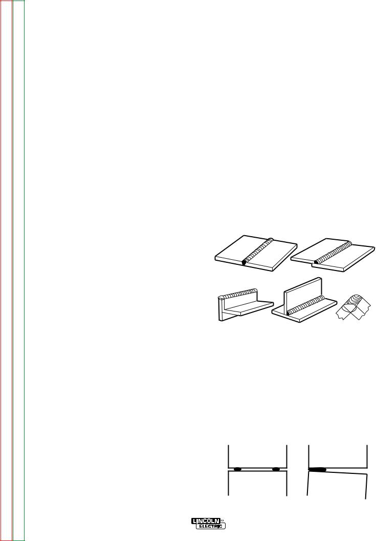
Return to Section TOC |
Return to Master TOC |
Return to Section TOC |
Return to Master TOC |
Return to Section TOC |
Return to Master TOC |
Return to Section TOC |
Return to Master TOC |
B-12 |
OPERATION |
B-12 |
PRACTICE
The best way of getting practice in the four skills that enable you to maintain:
1.Correct Welding Position.
2.Correct Way to Strike An Arc.
3.Correct Arc Length.
4.Correct Welding Speed.
is to spend a little more time on the following exercise.
Use the following: |
|
Mild Steel Plate: |
3/16” (4.8mm), or heavier. |
Electrode: |
1/8” (3.2mm) AWS 6011 |
|
(Fleetweld® 180) |
Current Setting: |
90-125 Amps AC |
Do the following:
1.Learn to strike the arc by scratching the electrode over the plate. Be sure the angle of the electrode is right and be sure to use both hands.
2.When you can strike an arc without sticking, practice the correct arc length. Learn to distinguish it by its sound.
3.When you are sure that you can hold a short, crackling arc, start moving. Look at the molten puddle constantly, and look for the ridge where the metal solidifies.
4.Run beads on a flat plate. Run them parallel to the top edge (the edge farthest away from you). This gives you practice in running straight welds, and also, it gives you an easy way to check your progress. The 10th weld will look considerably better than the first weld. By constantly checking on your mistakes and your progress, welding will soon be a routine matter.
Common Metals
Most metals found around the farm or small shop are low carbon steel, sometimes referred to as mild steel. Typical items made with this type of steel include most sheet metal, plate, pipe and rolled shapes such as channels, angle irons and “I” beams. This type of steel can usually be easily welded without special precautions. Some steel, however, contains higher carbon. Typical applications include wear plates, axles, connecting rods, shafts, plowshares and scraper blades.
These higher carbon steels can be welded successfully in most cases; however, care must be taken to follow proper procedures, including preheating the metal to be welded and, in some cases, carefully controlling the temperature during and after the welding process. For further information on identifying various types of steel and other metals, and for proper procedures for welding them, we suggest you purchase a copy of “New Lessons in Arc Welding”.
Regardless of the type of metal being welded, in order to get a quality weld, it is important that it be free of oil, paint, rust or other contaminant's.
Types of Welds
Five types of welding joints are: Butt Joints, Fillet Joints, Lap Joints, Edge Joints and Corner Joints.
Of these, the Butt Joint and Fillet Joint are the most common.
Butt Joint |
Lap Joint |
Edge Joint |
Fillet Joint |
Corner Joint |
Butt Joints
Butt Joints are the most widely used Joints. Place two plates side by side, leaving 1/16” (1.6mm) for thin metal to 1/8” (3.2mm) for heavy metal space between them in order to get deep penetration.
Tack the plates at both ends, otherwise the heat will cause the plates to move apart. (See drawing).
POWERARC® 5500
 Loading...