


RETURN TO MAIN MENU
IM641
May, 1999
POWER WAVE ™455 STT
For use with machines having Code Numbers: 10552, 10554
Safety Depends on You
Lincoln arc welding and cutting equipment is designed and built with safety in mind. However, your overall safety can be increased by proper installation ... and thoughtful operation on your part. DO NOT INSTALL, OPERATE OR REPAIR THIS EQUIPMENT WITHOUT READING THIS MANUAL AND THE SAFETY PRECAUTIONS CONTAINED THROUGHOUT. And, most importantly, think before you act and be careful.
IEC 974-1
OPERATOR’S MANUAL
|
|
|
|
|
|
|
|
|
|
|
|
|
|
|
|
|
|
|
|
|
|
|
|
|
|
|
|
|
|
|
|
|
|
|
|
|
|
|
|
|
|
|
|
|
|
|
|
|
|
|
|
|
|
|
|
|
|
|
|
|
|
|
World's Leader in Welding and Cutting Products |
|
|
|
|
|
Premier Manufacturer of Industrial Motors |
||
|
|
|
|
|
||||
• Sales and Service through Subsidiaries and Distributors Worldwide •
Cleveland, Ohio 44117-1199 U.S.A. TEL: 216.481.8100 FAX: 216.486.1751 WEB SITE: www.lincolnelectric.com
i
SAFETY
i
 WARNING
CALIFORNIA PROPOSITION 65 WARNINGS
Diesel engine exhaust and some of its constituents are known to the State of California to cause cancer, birth defects, and other reproductive harm.
The Above For Diesel Engines
The engine exhaust from this product contains chemicals known to the State of California to cause cancer, birth defects, or other reproductive harm.
The Above For Gasoline Engines
ARC WELDING CAN BE HAZARDOUS. PROTECT YOURSELF AND OTHERS FROM POSSIBLE SERIOUS INJURY OR DEATH. KEEP CHILDREN AWAY. PACEMAKER WEARERS SHOULD CONSULT WITH THEIR DOCTOR BEFORE OPERATING.
Read and understand the following safety highlights. For additional safety information, it is strongly recommended that you purchase a copy of “Safety in Welding & Cutting - ANSI Standard Z49.1” from the American Welding Society, P.O. Box 351040, Miami, Florida 33135 or CSA Standard W117.2-1974. A Free copy of “Arc Welding Safety” booklet E205 is available from the Lincoln Electric Company, 22801 St. Clair Avenue, Cleveland, Ohio 44117-1199.
BE SURE THAT ALL INSTALLATION, OPERATION, MAINTENANCE AND REPAIR PROCEDURES ARE PERFORMED ONLY BY QUALIFIED INDIVIDUALS.
FOR ENGINE powered equipment.
1.a. Turn the engine off before troubleshooting and maintenance work unless the maintenance work requires it to be running.
____________________________________________________
1.b. Operate engines in open, well-ventilated areas or vent the engine exhaust fumes
outdoors.
____________________________________________________
1.c. Do not add the fuel near an open flame welding arc or when the engine is running.
Stop the engine and allow it to cool before refueling to prevent spilled fuel from vaporizing on contact with hot engine parts and igniting. Do not spill fuel when filling tank. If fuel is spilled, wipe it up and do not start engine until fumes have been eliminated.
____________________________________________________
1.d. Keep all equipment safety guards, covers and devices in position and in good repair.Keep hands, hair, clothing and tools away from V-belts, gears, fans and all other moving parts when starting, operating or repairing equipment.
____________________________________________________
1.e. In some cases it may be necessary to remove safety guards to perform required maintenance. Remove guards only when necessary and replace them when the maintenance requiring their removal is complete. Always use the greatest care when working near moving parts.
___________________________________________________
1.f. Do not put your hands near the engine fan.
Do not attempt to override the governor or idler by pushing on the throttle control rods while the engine is running.
___________________________________________________
1.g. To prevent accidentally starting gasoline engines while turning the engine or welding generator during maintenance work, disconnect the spark plug wires, distributor cap or magneto wire as appropriate.
1.h. To avoid scalding, do not remove the radiator pressure cap when the engine is hot.
ELECTRIC AND MAGNETIC FIELDS may be dangerous
2.a. Electric current flowing through any conductor causes localized Electric and Magnetic Fields (EMF). Welding current creates EMF fields around welding cables and welding machines
2.b. EMF fields may interfere with some pacemakers, and welders having a pacemaker should consult their physician before welding.
2.c. Exposure to EMF fields in welding may have other health effects which are now not known.
2.d. All welders should use the following procedures in order to minimize exposure to EMF fields from the welding circuit:
2.d.1. Route the electrode and work cables together - Secure them with tape when possible.
2.d.2. Never coil the electrode lead around your body.
2.d.3. Do not place your body between the electrode and work cables. If the electrode cable is on your right side, the work cable should also be on your right side.
2.d.4. Connect the work cable to the workpiece as close as possible to the area being welded.
2.d.5. Do not work next to welding power source.
Mar ‘95
ii |
|
SAFETY |
|
ii |
|
|
|
|
|
|
|
|
|
|
ELECTRIC SHOCK can
kill.
3.a. The electrode and work (or ground) circuits are electrically “hot” when the welder is on. Do not touch these “hot” parts with your bare skin or wet clothing. Wear dry, hole-free
gloves to insulate hands.
3.b. Insulate yourself from work and ground using dry insulation. Make certain the insulation is large enough to cover your full area of physical contact with work and ground.
In addition to the normal safety precautions, if welding must be performed under electrically hazardous conditions (in damp locations or while wearing wet clothing; on metal structures such as floors, gratings or scaffolds; when in cramped positions such as sitting, kneeling or lying, if there is a high risk of unavoidable or accidental contact with the workpiece or ground) use the following equipment:
•Semiautomatic DC Constant Voltage (Wire) Welder.
•DC Manual (Stick) Welder.
•AC Welder with Reduced Voltage Control.
3.c. In semiautomatic or automatic wire welding, the electrode, electrode reel, welding head, nozzle or semiautomatic welding gun are also electrically “hot”.
3.d. Always be sure the work cable makes a good electrical connection with the metal being welded. The connection should be as close as possible to the area being welded.
3.e. Ground the work or metal to be welded to a good electrical (earth) ground.
3.f. Maintain the electrode holder, work clamp, welding cable and welding machine in good, safe operating condition. Replace damaged insulation.
3.g. Never dip the electrode in water for cooling.
3.h. Never simultaneously touch electrically “hot” parts of electrode holders connected to two welders because voltage between the two can be the total of the open circuit voltage of both welders.
3.i. When working above floor level, use a safety belt to protect yourself from a fall should you get a shock.
3.j. Also see Items 6.c. and 8.
ARC RAYS can burn.
4.a. Use a shield with the proper filter and cover plates to protect your eyes from sparks and the rays of the arc when welding or observing open arc welding. Headshield and filter lens should conform to ANSI Z87. I standards.
4.b. Use suitable clothing made from durable flame-resistant material to protect your skin and that of your helpers from the arc rays.
4.c. Protect other nearby personnel with suitable, non-flammable screening and/or warn them not to watch the arc nor expose themselves to the arc rays or to hot spatter or metal.
FUMES AND GASES can be dangerous.
5.a. Welding may produce fumes and gases hazardous to health. Avoid breathing these fumes and gases.When welding, keep your head out of the fume. Use enough ventilation and/or exhaust at the arc to keep
fumes and gases away from the breathing zone. When welding with electrodes which require special ventilation such as stainless or hard facing (see instructions on container or MSDS) or on lead or cadmium plated steel and other metals or coatings which produce highly toxic fumes, keep exposure as low as possible and below Threshold Limit Values (TLV) using local exhaust or mechanical ventilation. In confined spaces or in some circumstances, outdoors, a respirator may be required. Additional precautions are also required when welding on galvanized steel.
5.b. Do not weld in locations near chlorinated hydrocarbon vapors coming from degreasing, cleaning or spraying operations.
The heat and rays of the arc can react with solvent vapors to form phosgene, a highly toxic gas, and other irritating products.
5.c. Shielding gases used for arc welding can displace air and cause injury or death. Always use enough ventilation, especially in confined areas, to insure breathing air is safe.
5.d. Read and understand the manufacturer’s instructions for this equipment and the consumables to be used, including the material safety data sheet (MSDS) and follow your employer’s safety practices. MSDS forms are available from your welding distributor or from the manufacturer.
5.e. Also see item 1.b.
Mar ‘95
iii
SAFETY
iii

 WELDING SPARKS can

 cause fire or explosion.
6.a. Remove fire hazards from the welding area. If this is not possible, cover them to prevent the welding sparks from starting a fire.
Remember that welding sparks and hot materials from welding can easily go through small cracks and openings to adjacent areas. Avoid welding near hydraulic lines. Have a fire extinguisher readily available.
6.b. Where compressed gases are to be used at the job site, special precautions should be used to prevent hazardous situations. Refer to “Safety in Welding and Cutting” (ANSI
Standard Z49.1) and the operating information for the equipment being used.
6.c. When not welding, make certain no part of the electrode circuit is touching the work or ground. Accidental contact can cause overheating and create a fire hazard.
6.d. Do not heat, cut or weld tanks, drums or containers until the proper steps have been taken to insure that such procedures will not cause flammable or toxic vapors from substances inside. They can cause an explosion even though they have been “cleaned”. For information, purchase “Recommended Safe Practices for the Preparation for Welding and Cutting of Containers and Piping That Have Held Hazardous
Substances”, AWS F4.1 from the American Welding Society
(see address above).
6.e. Vent hollow castings or containers before heating, cutting or welding. They may explode.
6.f. Sparks and spatter are thrown from the welding arc. Wear oil free protective garments such as leather gloves, heavy shirt, cuffless trousers, high shoes and a cap over your hair. Wear ear plugs when welding out of position or in confined places. Always wear safety glasses with side shields when in a welding area.
6.g. Connect the work cable to the work as close to the welding area as practical. Work cables connected to the building framework or other locations away from the welding area increase the possibility of the welding current passing through lifting chains, crane cables or other alternate circuits. This can create fire hazards or overheat lifting chains or cables until they fail.
6.h. Also see item 1.c.
CYLINDER may explode


 if damaged.
7.a. Use only compressed gas cylinders
containing the correct shielding gas for the process used and properly operating regulators designed for the gas and
pressure used. All hoses, fittings, etc. should be suitable for the application and maintained in good condition.
7.b. Always keep cylinders in an upright position securely chained to an undercarriage or fixed support.
7.c. Cylinders should be located:
•Away from areas where they may be struck or subjected to physical damage.
•A safe distance from arc welding or cutting operations and any other source of heat, sparks, or flame.
7.d. Never allow the electrode, electrode holder or any other electrically “hot” parts to touch a cylinder.
7.e. Keep your head and face away from the cylinder valve outlet when opening the cylinder valve.
7.f. Valve protection caps should always be in place and hand tight except when the cylinder is in use or connected for use.
7.g. Read and follow the instructions on compressed gas cylinders, associated equipment, and CGA publication P-l,
“Precautions for Safe Handling of Compressed Gases in Cylinders,” available from the Compressed Gas Association 1235 Jefferson Davis Highway, Arlington, VA 22202.
FOR ELECTRICALLY powered equipment.
8.a. Turn off input power using the disconnect switch at the fuse box before working on the equipment.
8.b. Install equipment in accordance with the U.S. National Electrical Code, all local codes and the manufacturer’s recommendations.
8.c. Ground the equipment in accordance with the U.S. National Electrical Code and the manufacturer’s recommendations.
Mar ‘95

iv
SAFETY
iv
PRÉCAUTIONS DE SÛRETÉ
Pour votre propre protection lire et observer toutes les instructions et les précautions de sûreté specifiques qui parraissent dans ce manuel aussi bien que les précautions de sûreté générales suivantes:
Sûreté Pour Soudage A L’Arc
1.Protegez-vous contre la secousse électrique:
a.Les circuits à l’électrode et à la piéce sont sous tension quand la machine à souder est en marche. Eviter toujours tout contact entre les parties sous tension et la peau nue ou les vétements mouillés. Porter des gants secs et sans trous pour isoler les mains.
b.Faire trés attention de bien s’isoler de la masse quand on soude dans des endroits humides, ou sur un plancher metallique ou des grilles metalliques, principalement dans les positions assis ou couché pour lesquelles une grande partie du corps peut être en contact avec la masse.
c.Maintenir le porte-électrode, la pince de masse, le câble de soudage et la machine à souder en bon et sûr état defonctionnement.
d.Ne jamais plonger le porte-électrode dans l’eau pour le refroidir.
e.Ne jamais toucher simultanément les parties sous tension des porte-électrodes connectés à deux machines à souder parce que la tension entre les deux pinces peut être le total de la tension à vide des deux machines.
f.Si on utilise la machine à souder comme une source de courant pour soudage semi-automatique, ces precautions pour le porte-électrode s’applicuent aussi au pistolet de soudage.
2.Dans le cas de travail au dessus du niveau du sol, se protéger contre les chutes dans le cas ou on recoit un choc. Ne jamais enrouler le câble-électrode autour de n’importe quelle partie du corps.
3.Un coup d’arc peut être plus sévère qu’un coup de soliel, donc:
a.Utiliser un bon masque avec un verre filtrant approprié ainsi qu’un verre blanc afin de se protéger les yeux du rayonnement de l’arc et des projections quand on soude ou quand on regarde l’arc.
b.Porter des vêtements convenables afin de protéger la peau de soudeur et des aides contre le rayonnement de l‘arc.
c.Protéger l’autre personnel travaillant à proximité au soudage à l’aide d’écrans appropriés et non-inflammables.
4.Des gouttes de laitier en fusion sont émises de l’arc de soudage. Se protéger avec des vêtements de protection libres de l’huile, tels que les gants en cuir, chemise épaisse, pantalons sans revers, et chaussures montantes.
5.Toujours porter des lunettes de sécurité dans la zone de soudage. Utiliser des lunettes avec écrans lateraux dans les
zones où l’on pique le laitier.
6.Eloigner les matériaux inflammables ou les recouvrir afin de prévenir tout risque d’incendie dû aux étincelles.
7.Quand on ne soude pas, poser la pince à une endroit isolé de la masse. Un court-circuit accidental peut provoquer un échauffement et un risque d’incendie.
8.S’assurer que la masse est connectée le plus prés possible de la zone de travail qu’il est pratique de le faire. Si on place la masse sur la charpente de la construction ou d’autres endroits éloignés de la zone de travail, on augmente le risque de voir passer le courant de soudage par les chaines de levage, câbles de grue, ou autres circuits. Cela peut provoquer des risques d’incendie ou d’echauffement des chaines et des câbles jusqu’à ce qu’ils se rompent.
9.Assurer une ventilation suffisante dans la zone de soudage.
Ceci est particuliérement important pour le soudage de tôles galvanisées plombées, ou cadmiées ou tout autre métal qui produit des fumeés toxiques.
10.Ne pas souder en présence de vapeurs de chlore provenant d’opérations de dégraissage, nettoyage ou pistolage. La chaleur ou les rayons de l’arc peuvent réagir avec les vapeurs du solvant pour produire du phosgéne (gas fortement toxique) ou autres produits irritants.
11.Pour obtenir de plus amples renseignements sur la sûreté, voir le code “Code for safety in welding and cutting” CSA Standard W 117.2-1974.
PRÉCAUTIONS DE SÛRETÉ POUR LES MACHINES À SOUDER À TRANSFORMATEUR ET À REDRESSEUR
1.Relier à la terre le chassis du poste conformement au code de l’électricité et aux recommendations du fabricant. Le dispositif de montage ou la piece à souder doit être branché à une bonne mise à la terre.
2.Autant que possible, I’installation et l’entretien du poste seront effectués par un électricien qualifié.
3.Avant de faires des travaux à l’interieur de poste, la debrancher à l’interrupteur à la boite de fusibles.
4.Garder tous les couvercles et dispositifs de sûreté à leur place.
Mar. ‘93

v
Thank You
v
for selecting a QUALITY product by Lincoln Electric. We want you to take pride in operating this Lincoln Electric Company product
••• as much pride as we have in bringing this product to you!
Please Examine Carton and Equipment For Damage Immediately
When this equipment is shipped, title passes to the purchaser upon receipt by the carrier. Consequently, Claims for material damaged in shipment must be made by the purchaser against the transportation company at the time the shipment is received.
Please record your equipment identification information below for future reference. This information can be found on your machine nameplate.
Model Name & Number _____________________________________
Code & Serial Number _____________________________________
Date of Purchase _____________________________________
Whenever you request replacement parts for or information on this equipment always supply the information you have recorded above.
Read this Operators Manual completely before attempting to use this equipment. Save this manual and keep it handy for quick reference. Pay particular attention to the safety instructions we have provided for your protection. The level of seriousness to be applied to each is explained below:
 WARNING
This statement appears where the information must be followed exactly to avoid serious personal injury or loss of life.
 CAUTION
This statement appears where the information must be followed to avoid minor personal injury or damage to this equipment.
|
|
TABLE OF CONTENTS |
|
|
|
vi |
|
|
|
Page |
|||
|
|
Installation ....................................................................................................... |
Section A |
|||
|
|
Technical Specifications - Power Wave 455.......................................................... |
A-1 |
|||
|
|
Safety Precautions................................................................................................. |
A-2 |
|||
|
|
Select Suitable Location ........................................................................................ |
A-2 |
|||
|
|
Stacking .......................................................................................................... |
A-2 |
|||
|
|
Environmental Protection ................................................................................ |
A-2 |
|||
|
|
Lifting............................................................................................................... |
A-2 |
|||
|
|
Machine Grounding ............................................................................................... |
A-2 |
|||
|
|
High Frequency Protection .................................................................................... |
A-2 |
|||
|
|
Input Connection.................................................................................................... |
A-2 |
|||
|
|
Input Fuse and Supply Wire Considerations ......................................................... |
A-3 |
|||
|
|
Input Voltage Connection Procedure..................................................................... |
A-3 |
|||
|
|
Output Connections............................................................................................... |
A-3 |
|||
|
|
Voltage Sensing at the Work Piece ....................................................................... |
A-4 |
|||
|
|
Power Wave / Power Feed Wire Feeder Interconnections.................................... |
A-4 |
|||
|
|
Electrode and Work Leads - Electrode Positive Applications ......................... |
A-4 |
|||
|
|
Electrode and Work Leads - Electrode Negative Applications........................ |
A-4 |
|||
|
|
Control Cable Connections ............................................................................. |
A-4 |
|||
|
|
Power Feed Control Box Mounting ................................................................. |
A-4 |
|||
|
|
|
|
|
||
|
|
Operation ......................................................................................................... |
Section B |
|||
|
|
Safety Instructions ................................................................................................. |
B-1 |
|||
|
|
Graphic Symbols that appear on this machine or in this manual........................... |
B-2 |
|||
|
|
General Description............................................................................................... |
B-3 |
|||
|
|
Recommended Processes and Equipment ........................................................... |
B-3 |
|||
|
|
Design Features and Advantages ......................................................................... |
B-3 |
|||
|
|
Additional Features................................................................................................ |
B-3 |
|||
|
|
Welding Capability................................................................................................. |
B-4 |
|||
|
|
Limitations.............................................................................................................. |
B-4 |
|||
|
|
Compatible Lincoln Equipment.............................................................................. |
B-4 |
|||
|
|
Power Source Operation ....................................................................................... |
B-4 |
|||
|
|
Duty Cycle and Time Period ........................................................................... |
B-4 |
|||
|
|
Case Front Controls ........................................................................................ |
B-4 |
|||
|
|
Welding Adjustments ...................................................................................... |
B-5 |
|||
|
|
Detailed Weld Mode Descriptions ................................................................... |
B-5 |
|||
|
|
|
|
|
|
|
|
|
Accessories ..................................................................................................... |
Section C |
|||
|
|
Options / Accessories............................................................................................ |
C-1 |
|||
|
|
Factory Installed.............................................................................................. |
C-1 |
|||
|
|
Field Installed.................................................................................................. |
C-1 |
|||
|
|
|
|
|
|
|
|
|
Maintenance .................................................................................................... |
Section D |
|||
|
|
Safety Precautions ................................................................................................ |
D-1 |
|||
|
|
Routine Maintenance............................................................................................. |
D-1 |
|||
|
|
|
|
|
||
|
|
Troubleshooting .............................................................................................. |
Section E |
|||
|
|
Troubleshooting the Power Wave / Power Feed System using the Status LED ...E-1 |
||||
|
|
Safety Precautions................................................................................................. |
E-2 |
|||
|
|
How to Use Troubleshooting Guide....................................................................... |
E-2 |
|||
|
|
Troubleshooting Guide .......................................................................................... |
E-3 |
|||
|
|
|
|
|
||
|
|
Wiring Diagram and Dimension Print ............................................................ |
Section F |
|||
|
|
|
|
|
||
|
|
Parts Lists .................................................................................................... |
P335 Series |
|||
|
|
|
|
|
|
|

A-1 |
INSTALLATION |
A-1 |
|
|
|
TECHNICAL SPECIFICATIONS - POWER WAVE 455/STT
INPUT AT RATED OUTPUT - THREE PHASE ONLY
INPUT VOLTS |
OUTPUT CONDITIONS |
INPUT |
|
EXCEPT STT PROCESS |
CURRENT |
208V - 60HZ. |
450A@38V. 100% |
70 |
230V - 60HZ. |
450A@38V. 100% |
65 |
460V - 60HZ. |
450A@38V. 100% |
35 |
575V - 60HZ. |
450A@38V. 100% |
29 |
200V - 50HZ. |
400A@36V. 100% |
72 |
220V - 50HZ. |
400A@36V. 100% |
67 |
440V - 50HZ. |
400A@36V. 100% |
36 |
550V - 50HZ. |
400A@36V. 100% |
29 |
|
OUTPUT CONDITIONS |
|
|
STT PROCESS ALL VOLTAGES |
|
|
325A@33V. 100% |
|
OUTPUT CONDITIONS |
INPUT |
EXCEPT STT PROCESS |
CURRENT |
570A@43V. 60% |
87 |
570A@43V. 60% |
82 |
570A@43V. 60% |
48 |
570A@43V. 60% |
38 |
500A@40V. 60% |
79 |
500A@40V. 60% |
74 |
500A@40V. 60% |
41 |
500A@40V. 60% |
33 |
OUTPUT CONDITIONS STT PROCESS ALL VOLTAGES
325A@33V. 100%
OUTPUT
OPEN |
CURRENT |
|
PULSE |
PULSE |
PULSE AND |
AUXILIARY |
|
CIRCUIT |
RANGE |
|
FREQUENCY |
VOLTAGE |
BACKGROUND |
POWER |
|
VOLTAGE |
|
|
|
RANGE |
TIME RANGE |
|
|
|
|
|
|
|
|
|
|
75 VDC |
5 - 570 |
|
0.15 - 1000 Hz |
5 - 55 VDC |
100 MICRO SEC. - |
40 VDC AT |
|
|
|
|
|
|
|
3.3 SEC. |
10 AMPS |
|
|
|
|
|
|
|
115 VAC AT |
|
|
|
|
|
|
|
10 AMPS |
|
|
|
|
|
|
|
|
PROCESS CURRENT RANGES (DC) |
|
|
CURRENT |
|
|||
|
MIG/MAG |
|
|
50-570 Amps |
|
||
|
FCAW |
|
|
|
40-570 Amps |
|
|
|
SMAW |
|
|
|
30-570 Amps |
|
|
|
Pulse |
|
|
|
5-750 Amps |
|
|
|
STT |
|
|
|
40-325 Amps |
|
|
|
|
|
|
|
|
|
|
RECOMMENDED INPUT WIRE AND FUSE SIZES
INPUT |
OUTPUT AMPS/ |
INPUT AMPERE |
TYPE 75°C |
TYPE 75°C |
TYPE 75°C |
VOLTAGE / |
DUTY |
RATING ON |
COPPER WIRE |
GROUND WIRE |
(SUPER LAG) |
FREQUENCY |
CYCLE |
NAMEPLATE |
IN CONDUIT |
IN CONDUIT |
OR BREAKER |
|
|
|
AWG[IEC] SIZES |
AWG[IEC] SIZES |
SIZE (AMPS) |
|
|
|
(MM2) |
(MM2) |
|
208/60 |
450/100% |
70 |
4 (25) |
8 (10) |
80 AMP |
230/60 |
450/100% |
65 |
4 (25) |
8 (10) |
70 AMP |
460/60 |
450/100% |
35 |
8 (10) |
10 (6) |
40 AMP |
575/60 |
450/100% |
29 |
8 (10) |
10 (6) |
40 AMP |
|
|
|
|
|
|
200/50 |
400/100% |
72 |
4 (25) |
8 (10) |
80 AMP |
220/50 |
400/100% |
67 |
4 (25) |
8 (10) |
80 AMP |
440/50 |
400/100% |
31 |
8 (10) |
10 (6) |
40 AMP |
550/50 |
400/100% |
29 |
8 (10) |
10 (6) |
40 AMP |
|
|
|
|
|
|
PHYSICAL DIMENSIONS
HEIGHT |
WIDTH |
DEPTH |
WEIGHT |
26.10 in |
19.86 in |
32.88 in |
250 lbs. |
663 mm |
505 mm |
835 mm |
114 kg. |
|
|
|
|
TEMPERATURE RANGES
OPERATING TEMPERATURE RANGE |
STORAGE TEMPERATURE RANGE |
0°C to 40°C |
-50°C to 85°C |
|
|
POWER WAVE 455 STT

A-2 |
INSTALLATION |
A-2 |
|
|
|
Read this entire installation section before you start installation.
SAFETY PRECAUTIONS
WARNING
ELECTRIC SHOCK can kill.
•Only qualified personnel should perform this installation.
•Turn the input power OFF at the disconnect switch or fuse box before working on this equipment.
•Do not touch electrically hot parts.
•Always connect the Power Wave grounding lug (located inside the reconnect input access door) to a proper safety (Earth) ground.
-------------------------------------------------------------
SELECT SUITABLE LOCATION
Place the welder where clean cooling air can freely circulate in through the rear louvers and out through the case sides and bottom. Dirt, dust, or any foreign material that can be drawn into the welder should be kept at a minimum. Using filters on the air intake to prevent dirt from building up restricts air flow. Do not use such filters. Failure to observe these precautions can result in excessive operating temperatures and nuisance shutdowns.
This machine is equipped with F.A.N. (fan as needed) circuitry. The fan runs whenever the output is enabled, whether under loaded or open circuit conditions. The fan also runs for a period of time (approximately 5 minutes) after the output is disabled, to ensure all components are properly cooled.
If desired, the F.A.N. feature can be disabled (causing the fan to run whenever the power source is on). To disable F.A.N., connect leads 444 and X3A together at the output of the solid state fan control relay, located on the back of the Control PC board enclosure.
STACKING
Power Wave machines can be stacked to a maximum of 3 high. The bottom machine must always be placed on a firm, secure, level surface. There is a danger of machines toppling over if this precaution is not taken.
ENVIRONMENTAL PROTECTION
The Power Wave power source is rated IP21S and should not be subjected to falling water, nor should
any parts of it be submerged in water. Doing so may cause improper operation as well as pose a safety hazard. The best practice is to keep the machine in a dry, sheltered area.
LIFTING
Lift the machine by the lift bail only. The lift bail is designed to lift the power source only. Do not attempt to lift the Power Wave with accessories attached to it.
MACHINE GROUNDING
The frame of the welder must be grounded. A ground terminal marked with the symbol  is located inside the reconnect/input access door for this purpose. See your local and national electrical codes for proper grounding methods.
HIGH FREQUENCY PROTECTION
If possible, locate the Power Wave away from radio controlled machinery. The normal operation of the Power Wave may adversely affect the operation of RF controlled equipment, which may result in bodily injury or damage to the equipment.
INPUT CONNECTION
 WARNING
Only a qualified electrician should connect the input leads to the Power Wave. Connections should be made in accordance with all local and national electrical codes and the connection diagram located on the inside of the reconnect/input access door of the machine. Failure to do so may result in bodily injury or death.
-------------------------------------------------------------
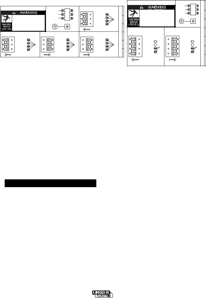
Use a three-phase supply line. A 1.75 inch (45 mm) diameter access hole for the input supply is located on the upper left case back next to the input access door. Connect L1, L2, L3 and ground according to the Input Supply Connection Diagram decal located on the inside of the input access door or refer to Figure A.1 following.
POWER WAVE 455 STT
A-3 |
INSTALLATION |
A-3 |
|
|
|
|
FIGUREE A..11--CONNECTIONDIAGRAMONCONNECTION/IRECONNECT/INPUTTACCESSDOOR |
|
|
|
|
|
|
|
|
|
|
|
|
|
/ 8 |
|
|
|
|
|
|
|
|
12 /-1 234 3 4 524 4 4 3% |
|
|
6 |
|
|
|
|
6 |
|
|
|
|
% ( & 7 , |
|
45 |
|
||||
|
|
|
|
|
|
|
|
|
|||||
|
|
|
|
|
|
|
! "#$ |
|
|
|
|||
% ( & 7 , |
45 |
|
|
/ 0 |
|
|
|
12 /-1 234 3 4 524 4 4 3% |
|||||
|
|
|
|
|
% # &$! |
|
|
|
|
||||
! "#$ |
|
|
|
. . |
|
" ! ' |
|
|
|
|
|
||
|
|
|
|
% ($) #))* ) ! # |
|
|
|
|
|||||
% # &$! |
|
|
|
|
|
|
|
|
|
||||
" ! ' |
|
|
|
|
|
|
|
)* +(#) , ' $()' #))- |
|
|
|
|
|
% ($) #))* ) ! # |
|
|
|
|
|
|
|
|
|
||||
|
|
|
|
|
( !$+( " |
|
|
|
|
||||
)* +(#) , ' $()' #))- |
|
|
|
|
|
|
|
|
|
|
|
|
|
|
|
|
|
|
|
|
|
|
|
|
|
|
|
( !$+( " |
|
|
|
|
|
|
|
|
0 |
|
|
|
|
|
|
|
|
|
|
|
|
|
|
|
|||
|
|
|
|
|
|
|
|
|
|
||||
|
|
|
|
|
|
|
|
|
|
|
|
|
|
|
. . |
|
|
. . |
|
. . |
|
|
. . |
|
. . |
|
|
|
|
|
|
|
|
|
|
|
|||||
|
|
|
|
|
|
||||||||
|
|
|
|
|
|
|
|
|
|
|
|
||
|
|
|
|
|
|
|
|
|
|
|
|||
|
|
|
|
|
|
|
|
0 |
|
0 |
|
|
|
|
|
|
|
|
|
|
|
|
|
|
|
|
|
NOTE: Turn main input power to the machine OFF before performing reconnect procedure. Failure to do so will result in damage to the machine. DO NOT switch the reconnect bar with machine power ON.
INPUT FUSE AND SUPPLY WIRE CONSIDERATIONS
Refer to the Technical Specifications at the beginning of this Installation section for recommended fuse and wire sizes. Fuse the input circuit with the recommended super lag fuse or delay type breakers (also called “inverse time” or “thermal/magnetic” circuit breakers). Choose an input and grounding wire size according to local or national electrical codes. Using fuses or circuit breakers smaller than recommended may result in “nuisance” shut-offs from welder inrush currents, even if the machine is not being used at high currents.
instructions located on the inside of the input access door or in Figure A.1. If the main reconnect switch is placed in the wrong position, the welder will not produce output power. If the Auxiliary (“A”) lead is placed in the wrong position, there are two possible results. If the lead is placed in a position higher than the applied line voltage, the welder may not come on at all. If the Auxiliary (“A”) lead is placed in a position lower than the applied line voltage, the welder will not come on, and the two circuit breakers in the reconnect area will open. If this occurs, turn off the input voltage, properly connect the “A” lead, reset the breakers, and try again.
INPUT VOLTAGE RECONNECT PROCEDURE
 WARNING
Only a qualified electrician should connect the input leads to the Power Wave. Connections should be made in accordance with all local and national electrical codes and the connection diagram located on the inside of the reconnect/input access door of the machine. Failure to do so may result in bodily injury or
death.
------------------------------------------------------------------------
Welders are shipped connected for the highest input voltage listed on the rating plate. To move this connection to a different input voltage, refer to reconnect
OUTPUT CONNECTIONS
Use the largest welding (electrode and ground) cables possible — at least 2/0, 4/0 preferred, copper wire — even if the average output current would not normally require it. When pulsing, the pulse current can exceeds 650 amps. Voltage drops can become excessive, leading to poor welding characteristics, if undersized welding cables are used.
To avoid interference problems with other equipment and to achieve the best possible operation, route all cables directly to the work or wire feeder. Avoid excessive lengths, bundle the electrode and ground cables together where practical, and do not coil excess cable.
POWER WAVE 455 STT
 Loading...