


V250-S
Table of contents
 Loading...
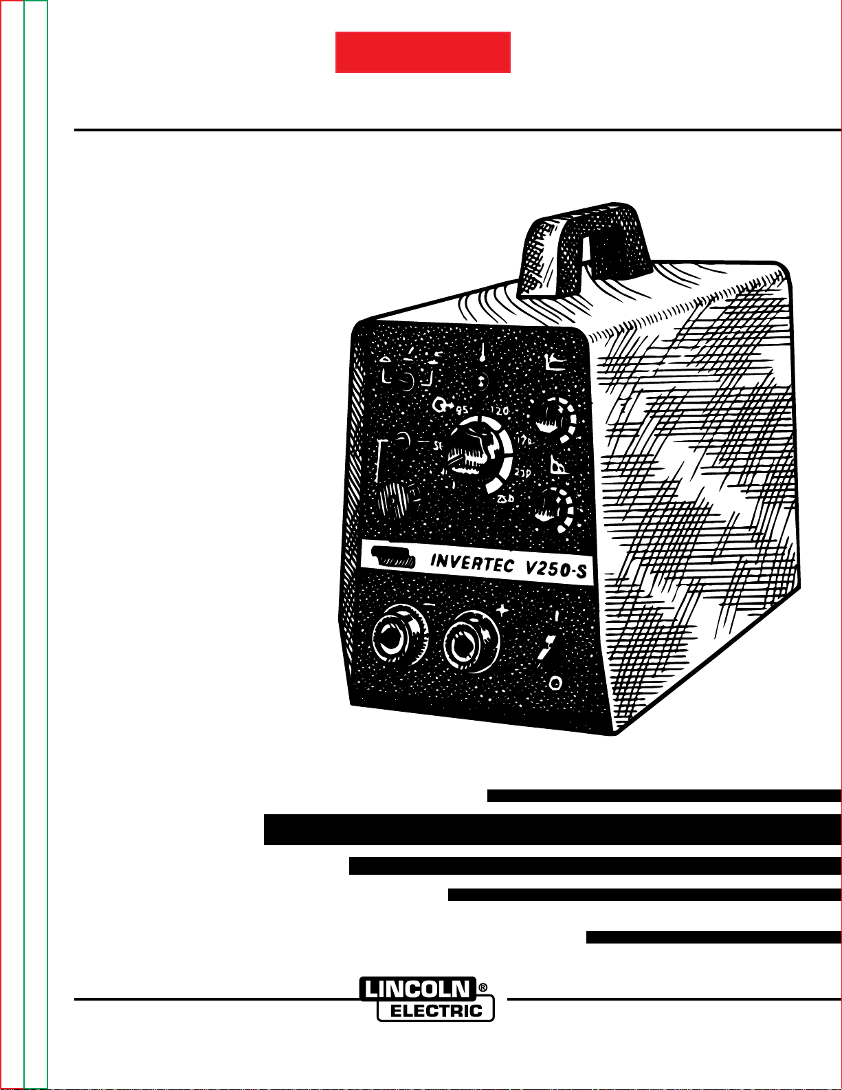
RETURN TO MAIN INDEX
SVM124-A
INVERTEC V250-S
For use with machine Code Numbers 10102 to 10188
Safety Depends on You
Lincoln arc welding and cutting
equipment is designed and built
with safety in mind. However, your
overall safety can be increased by
proper installation ... and thoughtful operation on your part. DO
NOT INSTALL, OPERATE OR
REPAIR THIS EQUIPMENT
WITHOUT READING THIS
MANUAL AND THE SAFETY
PRECAUTIONS CONTAINED
THROUGHOUT. And, most
importantly, think before you act
and be careful.
July, 1996
View Safety Info View Safety Info View Safety Info View Safety Info
Return to Master TOC Return to Master TOC Return to Master TOC Return to Master TOC
World's Leader in Welding and Cutting Products Premier Manufacturer of Industrial Motors
SERVICE MANUAL
Sales and Service through Subsidiaries and Distributors Worldwide
22801 St. Clair Ave. Cleveland, Ohio 44117-1199 U.S.A. Tel. (216) 481-8100
i
SAFETY
i
WARNING
CALIFORNIA PROPOSITION 65 WARNINGS
Diesel engine exhaust and some of its constituents
are known to the State of California to cause cancer, birth defects, and other reproductive harm.
The Above For Diesel Engines
ARC WELDING CAN BE HAZARDOUS. PROTECT YOURSELF AND OTHERS FROM POSSIBLE SERIOUS INJURY OR DEATH.
KEEP CHILDREN AWAY. PACEMAKER WEARERS SHOULD CONSULT WITH THEIR DOCTOR BEFORE OPERATING.
Read and understand the following safety highlights. For additional safety information, it is strongly recommended that you
purchase a copy of “Safety in Welding & Cutting - ANSI Standard Z49.1” from the American Welding Society, P.O. Box
351040, Miami, Florida 33135 or CSA Standard W117.2-1974. A Free copy of “Arc Welding Safety” booklet E205 is available
from the Lincoln Electric Company, 22801 St. Clair Avenue, Cleveland, Ohio 44117-1199.
BE SURE THAT ALL INSTALLATION, OPERATION, MAINTENANCE AND REPAIR PROCEDURES ARE
PERFORMED ONLY BY QUALIFIED INDIVIDUALS.
The engine exhaust from this product contains
chemicals known to the State of California to cause
cancer, birth defects, or other reproductive harm.
The Above For Gasoline Engines
FOR ENGINE
powered equipment.
1.a. Turn the engine off before troubleshooting and maintenance
work unless the maintenance work requires it to be running.
____________________________________________________
1.b.Operate engines in open, well-ventilated
areas or vent the engine exhaust fumes
outdoors.
____________________________________________________
1.c. Do not add the fuel near an open flame
welding arc or when the engine is running.
Stop the engine and allow it to cool before
refueling to prevent spilled fuel from vaporizing on contact with hot engine parts and
igniting. Do not spill fuel when filling tank. If
fuel is spilled, wipe it up and do not start
engine until fumes have been eliminated.
____________________________________________________
1.d. Keep all equipment safety guards, covers
and devices in position and in good
repair.Keep hands, hair, clothing and tools
away from V-belts, gears, fans and all other
moving parts when starting, operating or
repairing equipment.
____________________________________________________
1.e. In some cases it may be necessary to remove safety
guards to perform required maintenance. Remove
guards only when necessary and replace them when the
maintenance requiring their removal is complete.
Always use the greatest care when working near moving
parts.
___________________________________________________
1.f. Do not put your hands near the engine fan. Do not attempt
to override the governor or idler by pushing on the throttle
control rods while the engine is running.
___________________________________________________
1.g. To prevent accidentally starting gasoline engines while
turning the engine or welding generator during maintenance
work, disconnect the spark plug wires, distributor cap or
magneto wire as appropriate.
Return to Master TOC Return to Master TOC Return to Master TOC Return to Master TOC
1.h. To avoid scalding, do not remove the
radiator pressure cap when the engine is
hot.
ELECTRIC AND
MAGNETIC FIELDS
may be dangerous
2.a. Electric current flowing through any conductor causes
localized Electric and Magnetic Fields (EMF). Welding
current creates EMF fields around welding cables and
welding machines
2.b. EMF fields may interfere with some pacemakers, and
welders having a pacemaker should consult their physician
before welding.
2.c. Exposure to EMF fields in welding may have other health
effects which are now not known.
2.d. All welders should use the following procedures in order to
minimize exposure to EMF fields from the welding circuit:
2.d.1.
Route the electrode and work cables together - Secure
them with tape when possible.
2.d.2. Never coil the electrode lead around your body.
2.d.3. Do not place your body between the electrode and
work cables. If the electrode cable is on your right
side, the work cable should also be on your right side.
2.d.4. Connect the work cable to the workpiece as close as
possible to the area being welded.
2.d.5. Do not work next to welding power source.
Mar ‘95
ii
SAFETY
ii
ELECTRIC SHOCK can
kill.
3.a. The electrode and work (or ground) circuits
are electrically “hot” when the welder is on.
Do not touch these “hot” parts with your bare
skin or wet clothing. Wear dry, hole-free
gloves to insulate hands.
3.b. Insulate yourself from work and ground using dry insulation.
Make certain the insulation is large enough to cover your full
area of physical contact with work and ground.
In addition to the normal safety precautions, if welding
must be performed under electrically hazardous
conditions (in damp locations or while wearing wet
clothing; on metal structures such as floors, gratings or
scaffolds; when in cramped positions such as sitting,
kneeling or lying, if there is a high risk of unavoidable or
accidental contact with the workpiece or ground) use
the following equipment:
• Semiautomatic DC Constant Voltage (Wire) Welder.
• DC Manual (Stick) Welder.
• AC Welder with Reduced Voltage Control.
3.c. In semiautomatic or automatic wire welding, the electrode,
electrode reel, welding head, nozzle or semiautomatic
welding gun are also electrically “hot”.
3.d. Always be sure the work cable makes a good electrical
connection with the metal being welded. The connection
should be as close as possible to the area being welded.
3.e. Ground the work or metal to be welded to a good electrical
(earth) ground.
ARC RAYS can burn.
4.a. Use a shield with the proper filter and cover
plates to protect your eyes from sparks and
the rays of the arc when welding or observing
open arc welding. Headshield and filter lens
should conform to ANSI Z87. I standards.
4.b. Use suitable clothing made from durable flame-resistant
material to protect your skin and that of your helpers from
the arc rays.
4.c. Protect other nearby personnel with suitable, non-flammable
screening and/or warn them not to watch the arc nor expose
themselves to the arc rays or to hot spatter or metal.
FUMES AND GASES
can be dangerous.
5.a.Welding may produce fumes and gases
hazardous to health. Avoid breathing these
fumes and gases.When welding, keep
your head out of the fume. Use enough
ventilation and/or exhaust at the arc to keep
fumes and gases away from the breathing zone. When
welding with electrodes which require special
ventilation such as stainless or hard facing (see
instructions on container or MSDS) or on lead or
cadmium plated steel and other metals or coatings
which produce highly toxic fumes, keep exposure as
low as possible and below Threshold Limit Values (TLV)
using local exhaust or mechanical ventilation. In
confined spaces or in some circumstances, outdoors, a
respirator may be required. Additional precautions are
also required when welding on galvanized steel.
3.f.
Maintain the electrode holder, work clamp, welding cable and
welding machine in good, safe operating condition. Replace
damaged insulation.
3.g. Never dip the electrode in water for cooling.
3.h. Never simultaneously touch electrically “hot” parts of
electrode holders connected to two welders because voltage
between the two can be the total of the open circuit voltage
of both welders.
3.i. When working above floor level, use a safety belt to protect
yourself from a fall should you get a shock.
3.j. Also see Items 6.c. and 8.
5.b.
Do not weld in locations near chlorinated hydrocarbon
coming from degreasing, cleaning or spraying operations.
The heat and rays of the arc can react with solvent vapors
form phosgene, a highly toxic gas, and other irritating
products.
5.c. Shielding gases used for arc welding can displace air and
cause injury or death. Always use enough ventilation,
especially in confined areas, to insure breathing air is safe.
5.d. Read and understand the manufacturer’s instructions for this
equipment and the consumables to be used, including the
material safety data sheet (MSDS) and follow your
employer’s safety practices. MSDS forms are available from
your welding distributor or from the manufacturer.
5.e. Also see item 1.b.
Mar ‘95
vapors
to
Return to Master TOC Return to Master TOC Return to Master TOC Return to Master TOC
iii
SAFETY
iii
WELDING SPARKS can
cause fire or explosion.
6.a.
Remove fire hazards from the welding area.
If this is not possible, cover them to prevent
the welding sparks from starting a fire.
materials from welding can easily go through small cracks
and openings to adjacent areas. Avoid welding near
hydraulic lines. Have a fire extinguisher readily available.
6.b. Where compressed gases are to be used at the job site,
special precautions should be used to prevent hazardous
situations. Refer to “Safety in Welding and Cutting” (ANSI
Standard Z49.1) and the operating information for the
equipment being used.
6.c. When not welding, make certain no part of the electrode
circuit is touching the work or ground. Accidental contact
can cause overheating and create a fire hazard.
6.d. Do not heat, cut or weld tanks, drums or containers until the
proper steps have been taken to insure that such procedures
will not cause flammable or toxic vapors from substances
inside. They can cause an explosion even
been “cleaned”. For information, purchase “Recommended
Safe Practices for the
Containers and Piping That Have Held Hazardous
Substances”, AWS F4.1 from the American Welding Society
(see address above).
6.e. Vent hollow castings or containers before heating, cutting or
welding. They may explode.
6.f.
Sparks and spatter are thrown from the welding arc. Wear oil
free protective garments such as leather gloves, heavy shirt,
cuffless trousers, high shoes and a cap over your hair. Wear
ear plugs when welding out of position or in confined places.
Always wear safety glasses with side shields when in a
welding area.
6.g. Connect the work cable to the work as close to the welding
area as practical. Work cables connected to the building
framework or other locations away from the welding area
increase the possibility of the welding current passing
through lifting chains, crane cables or other alternate circuits. This can create fire hazards or overheat lifting chains
or cables until they fail.
6.h. Also see item 1.c.
Remember that welding sparks and hot
though
they have
Preparation
for Welding and Cutting of
CYLINDER may explode
if damaged.
7.a. Use only compressed gas cylinders
containing the correct shielding gas for the
process used and properly operating
regulators designed for the gas and
pressure used. All hoses, fittings, etc. should be suitable for
the application and maintained in good condition.
7.b. Always keep cylinders in an upright position securely
chained to an undercarriage or fixed support.
7.c. Cylinders should be located:
•Away from areas where they may be struck or subjected to
physical damage.
• A safe distance from arc welding or cutting operations and
any other source of heat, sparks, or flame.
7.d. Never allow the electrode, electrode holder or any other
electrically “hot” parts to touch a cylinder.
7.e. Keep your head and face away from the cylinder valve outlet
when opening the cylinder valve.
7.f. Valve protection caps should always be in place and hand
tight except when the cylinder is in use or connected for
use.
7.g. Read and follow the instructions on compressed gas
cylinders, associated equipment, and CGA publication P-l,
“Precautions for Safe Handling of Compressed Gases in
Cylinders,” available from the Compressed Gas Association
1235 Jefferson Davis Highway, Arlington, VA 22202.
FOR ELECTRICALLY
powered equipment.
8.a. Turn off input power using the disconnect
switch at the fuse box before working on
the equipment.
8.b. Install equipment in accordance with the U.S. National
Electrical Code, all local codes and the manufacturer’s
recommendations.
8.c. Ground the equipment in accordance with the U.S. National
Electrical Code and the manufacturer’s recommendations.
Return to Master TOC Return to Master TOC Return to Master TOC Return to Master TOC
Mar ‘95

iv
SAFETY
iv
PRÉCAUTIONS DE SÛRETÉ
Pour
votre propre protection lire et observer toutes les instructions et les précautions de sûreté specifiques qui parraissent
dans ce manuel aussi bien que les précautions de sûreté
générales suivantes:
Sûreté Pour Soudage A L’Arc
1. Protegez-vous contre la secousse électrique:
a. Les circuits à l’électrode et à la piéce sont sous tension
quand la machine à souder est en marche. Eviter toujours
tout contact entre les parties sous tension et la peau nue
ou les vétements mouillés. Porter des gants secs et sans
trous pour isoler les mains.
b. Faire trés attention de bien s’isoler de la masse quand on
soude dans des endroits humides, ou sur un plancher
metallique ou des grilles metalliques, principalement dans
les positions assis ou couché pour lesquelles une
grande partie du corps peut être en contact avec la
masse.
c. Maintenir le porte-électrode, la pince de masse, le câble
de soudage et la machine à souder en bon et sûr état
defonctionnement.
d.Ne jamais plonger le porte-électrode dans l’eau pour le
refroidir.
e. Ne jamais toucher simultanément les parties sous tension
des porte-électrodes connectés à deux machines à souder parce que la tension entre les deux pinces peut être le
total de la tension à vide des deux machines.
f. Si on utilise la machine à souder comme une source de
courant pour soudage semi-automatique, ces precautions
pour le porte-électrode s’applicuent aussi au pistolet de
soudage.
5. Toujours porter des lunettes de sécurité dans la zone de
soudage. Utiliser des lunettes avec écrans lateraux dans les
zones où l’on pique le laitier.
6. Eloigner les matériaux inflammables ou les recouvrir afin de
prévenir tout risque d’incendie dû aux étincelles.
7. Quand on ne soude pas, poser la pince à une endroit isolé de
la masse. Un court-circuit accidental peut provoquer un
échauffement et un risque d’incendie.
8. S’assurer que la masse est connectée le plus prés possible
de la zone de travail qu’il est pratique de le faire. Si on place
la masse sur la charpente de la construction ou d’autres
endroits éloignés de la zone de travail, on augmente le risque
de voir passer le courant de soudage par les chaines de levage, câbles de grue, ou autres circuits. Cela peut provoquer
des risques d’incendie ou d’echauffement des chaines et des
câbles jusqu’à ce qu’ils se rompent.
9. Assurer une ventilation suffisante dans la zone de soudage.
Ceci est particuliérement important pour le soudage de tôles
galvanisées plombées, ou cadmiées ou tout autre métal qui
produit des fumeés toxiques.
10. Ne pas souder en présence de vapeurs de chlore provenant
d’opérations de dégraissage, nettoyage ou pistolage. La
chaleur ou les rayons de l’arc peuvent réagir avec les
vapeurs du solvant pour produire du phosgéne (gas fortement toxique) ou autres produits irritants.
11. Pour obtenir de plus amples renseignements sur la sûreté,
voir le code “Code for safety in welding and cutting” CSA
Standard W 117.2-1974.
2. Dans le cas de travail au dessus du niveau du sol, se protéger contre les chutes dans le cas ou on recoit un choc. Ne
jamais enrouler le câble-électrode autour de n’importe quelle
partie du corps.
3. Un coup d’arc peut être plus sévère qu’un coup de soliel,
donc:
a. Utiliser un bon masque avec un verre filtrant approprié
ainsi qu’un verre blanc afin de se protéger les yeux du
rayonnement de l’arc et des projections quand on soude
ou quand on regarde l’arc.
b. Porter des vêtements convenables afin de protéger la
peau de soudeur et des aides contre le rayonnement de
l‘arc.
c. Protéger l’autre personnel travaillant à proximité au
soudage à l’aide d’écrans appropriés et non-inflammables.
4. Des gouttes de laitier en fusion sont émises de l’arc de
soudage. Se protéger avec des vêtements de protection
libres de l’huile, tels que les gants en cuir, chemise épaisse,
pantalons sans revers, et chaussures montantes.
Return to Master TOC Return to Master TOC Return to Master TOC Return to Master TOC
PRÉCAUTIONS DE SÛRETÉ POUR
LES MACHINES À SOUDER À
TRANSFORMATEUR ET À
REDRESSEUR
1. Relier à la terre le chassis du poste conformement au code
de l’électricité et aux recommendations du fabricant. Le dispositif de montage ou la piece à souder doit être branché à
une bonne mise à la terre.
2. Autant que possible, I’installation et l’entretien du poste
seront effectués par un électricien qualifié.
3. Avant de faires des travaux à l’interieur de poste, la
debrancher à l’interrupteur à la boite de fusibles.
4. Garder tous les couvercles et dispositifs de sûreté à leur
Mar. ‘93

MASTER TABLE OF CONTENTS FOR ALL SECTIONS
vi
RETURN TO MAIN INDEX
INSTALLATION .......................................................................................................................SECTION A
TECHNICAL SPECIFICATIONS..................................................................................................A-2
SAFETY PRECAUTIONS ............................................................................................................A-3
SELECT SUITABLE LOCATION..................................................................................................A-3
INPUT CONNECTIONS...............................................................................................................A-3
INPUT VOLTAGE RECONNECT PROCEDURE.........................................................................A-4
OUTPUT CONNECTIONS...........................................................................................................A-5
OPERATION .......................................................................................................................SECTION B
SAFETY INSTRUCTIONS ...........................................................................................................B-2
GENERAL DESCRIPTION...........................................................................................................B-2
CONTROLS AND SETTINGS......................................................................................................B-3
CONSTANT CURRENT PROCESSES........................................................................................B-4
PARALLEL OPERATION.............................................................................................................B-5
OVERLOAD PROTECTION.........................................................................................................B-5
THERMAL PROTECTION............................................................................................................B-5
ACCESSORIES .......................................................................................................................SECTION C
OPTIONS / ACCESSORIES........................................................................................................C-2
CABLE PLUGS......................................................................................................................C-2
REMOTE CONTROLS ..........................................................................................................C-2
MAINTENANCE .......................................................................................................................SECTION D
INPUT FILTER CAPACITOR DISCHARGE PROCEDURE.........................................................D-2
ROUTINE MAINTENANCE..........................................................................................................D-3
FILTER CAPACITOR CONDITIONING ......................................................................................D-3
LOCATION OF MAINTENANCE COMPONENTS.......................................................................D-4
PAGE
THEORY OF OPERATION.........................................................................................................SECTION E
GENERAL DESCRIPTION...........................................................................................................E-2
INPUT LINE VOLTAGE................................................................................................................E-2
PRE-CHARGE AND PROTECTION............................................................................................E-3
MAIN TRANSFORMER................................................................................................................E-4
OUTPUT RECTIFICATION AND CONTROL...............................................................................E-5
PROTECTION CIRCUITS............................................................................................................E-6
INSULATED GATE BIPOLAR TRANSISTOR (IGBT) OPERATION............................................E-7
PULSE WIDTH MODULATION (PWM)........................................................................................E-8
TROUBLESHOOTING................................................................................................................SECTION F
HOW TO USE TROUBLESHOOTING GUIDE ......................................................................F-2
PC BOARD TROUBLESHOOTING PROCEDURES.............................................................F-3
TROUBLESHOOTING GUIDE...............................................................................................F-4
TEST PROCEDURES..........................................................................................................F-11
REPAIR AND REPLACEMENT PROCEDURES.................................................................F-43
RETEST AFTER REPAIR....................................................................................................F-77
ELECTRICAL DIAGRAMS.........................................................................................................SECTION G
PARTS MANUAL ................................................................................................................................P-244
INVERTEC V250-S

SECTION-A-1
TECHNICAL SPECIFICATIONS..................................................................................................A-2
SAFETY PRECAUTIONS ............................................................................................................A-3
SELECT SUITABLE LOCATION..................................................................................................A-3
STACKING.............................................................................................................................A-3
TILTING.................................................................................................................................A-3
HIGH FREQUENCY PRECAUTIONS ...................................................................................A-3
INPUT CONNECTIONS...............................................................................................................A-3
GROUND CONNECTION......................................................................................................A-3
INPUT SUPPLY CONNECTIONS .........................................................................................A-3
POWER INPUT CONNECTION FOR 60HZ MACHINES......................................................A-3
POWER INPUT CONNECTION FOR 50/60 HZ MACHINES................................................A-4
INPUT FUSE AND SUPPLY WIRE .......................................................................................A-4
INPUT VOLTAGE RECONNECT PROCEDURE.........................................................................A-4
OUTPUT CONNECTIONS...........................................................................................................A-5
REMOTE CONTROL RECEPTACLE....................................................................................A-5
OUTPUT CABLES.................................................................................................................A-5
QUICK DISCONNECT PLUGS..............................................................................................A-5
INSTALLATION
TABLE OF CONTENTS
-INSTALLATION SECTION-
SECTION-A-1
Return to Master TOC Return to Master TOC Return to Master TOC Return to Master TOC
INVERTEC V250-S
A-2
INSTALLATION
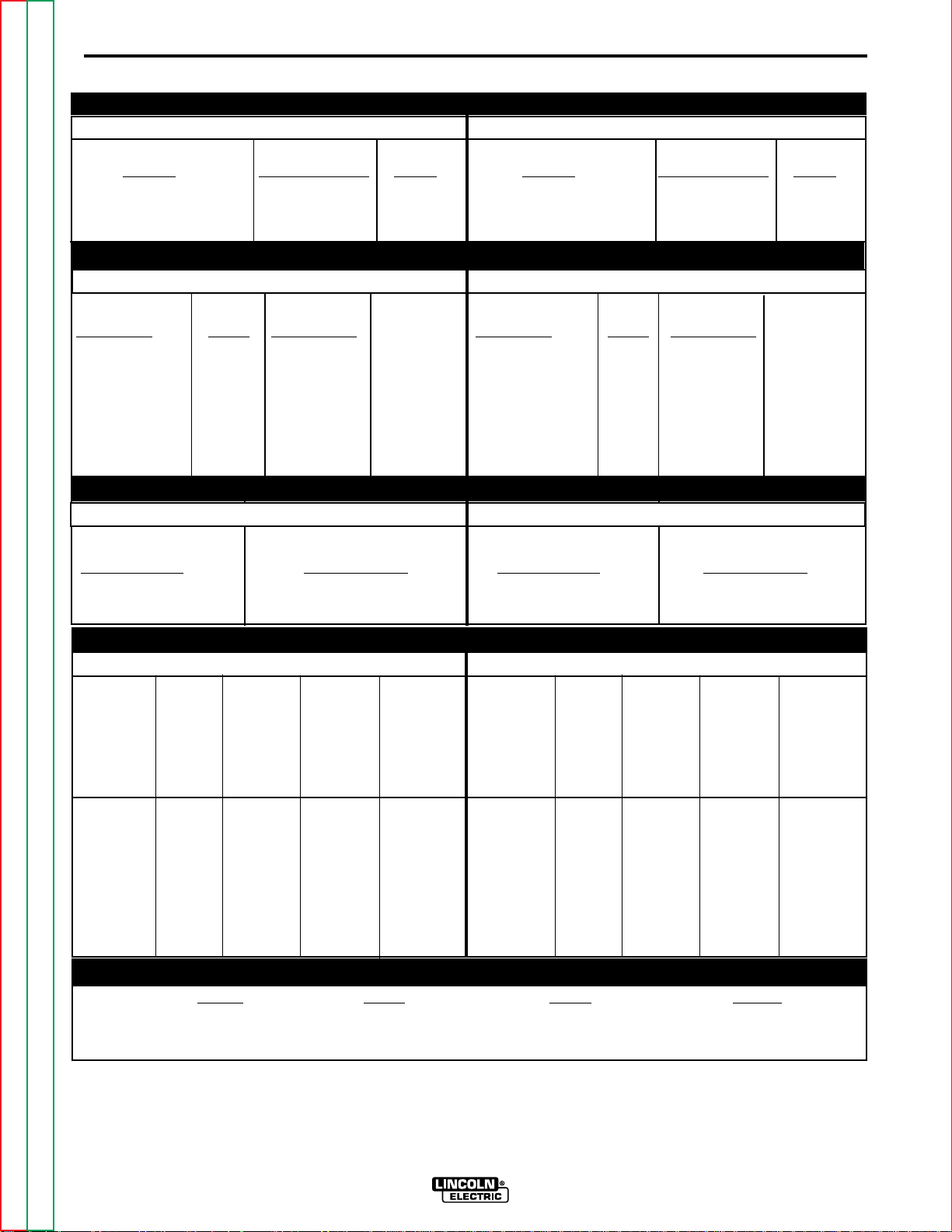
Technical Specifications - Invertec V250-S
INPUT
THREE PHASE SINGLE PHASE
Standard Input Current
Voltage
208/230/460 34/32/16 60Hz
200/220/400/440 35/33/18/17 50/60 Hz
THREE PHASE SINGLE PHASE
at Rated Output Model
208/230/460 60Hz 59/57/29 60Hz
200/220/400/440 50/60 Hz 58/58/30/30 50/60 Hz
RATED OUTPUT
Standard Input Current
Voltage
at Rated Output Model
A-2
Duty Cycle
(1)
Amps Rated Amps Model
35% Duty Cycle 250 30 60Hz
60% Duty Cycle 200 28-32 60Hz
100% Duty Cycle 165 26.5 60Hz
35% Duty Cycle 250 28†-30 50/60Hz
60% Duty Cycle 200 29-32 50/60Hz
100% Duty Cycle 165 26.5 50/60Hz
THREE PHASE SINGLE PHASE
Volts at
Welding Constant Open
Current Range
Circuit Voltage
1-250 Amps 65-80 VDC
RECOMMENDED INPUT WIRE AND FUSE SIZES
THREE PHASE SINGLE PHASE
Type 75°C
Type 75°C Copper
Fuse Input Copper Ground
(Superlag) Ampere Wire in Wire in
Input or Rating Conduit Conduit
Voltage Breaker on AWG (IEC) AWG (IEC)
Frequency
(2)
Size Nameplate Sizes Sizes
Duty Cycle
(1)
Amps Rated Amps Model
35% Duty Cycle 250 27†-30 60Hz
60% Duty Cycle 200 28-32 60Hz
100% Duty Cycle 165 26.5 60Hz
35% Duty Cycle 250 26†-30 50/60Hz
60% Duty Cycle 200 28-32 50/60Hz
100% Duty Cycle 165 26.5 50/60Hz
OUTPUT
Welding Constant Open
Volts at
Current Range
1-250 Amps 65-80 VDC
Fuse Input Copper Ground
(Superlag) Ampere Wire in Wire in
Input or Rating Conduit Conduit
Voltage Breaker on AWG (IEC) AWG (IEC)
Frequency
(2)
Size Nameplate Sizes Sizes
Circuit Voltage
Type 75°C Copper
Type 75°C
208/60 50 34 10 (6mm2) 10 (6mm2)
230/60 50 32 10(6mm2) 10 (6mm2)
460/60 30 16 10 (6mm2) 10 (6mm2)
200/50/60 50 35 10 (6mm2) 10 (6mm2)
220/50/60 50 33 10 (6mm2) 10 (6mm2)
400/50/60 30 18 10 (6mm2) 10 (6mm2)
440/50/60 30 17 10 (6mm2) 10 (6mm2)
(1) Based on a 10 min. period.
(2) Input voltage must be within ±10% of rated value.
(3) For 1 phase use on 208 or 230 VAC input with output usage above 175A/60% or 200A/35%, the #10 input line cord supplied with the unit should be changed to a
#8 or larger conductor cord.
(†)
200 & 208VAC input may not meet NEMA/IEC specifications at 250 Amps.
Return to Master TOC Return to Master TOC Return to Master TOC Return to Master TOC
Return to Section TOC Return to Section TOC Return to Section TOC Return to Section TOC
(3)
208/60
(3)
230/60
460/60 40 29 10 (6mm2) 10 (6mm2)
200/50/60 80 58 8 (16mm2) 10 (6mm2)
220/50/60 80 58 8 (16mm2) 10 (6mm2)
400/50/60 40 30 10 (6mm2) 10 (6mm2)
440/50/60 40 30 10 (6mm2) 10 (6mm2)
80 59 8 (10mm2) 10 (6mm2)
80 57 8 (10mm2) 10 (6mm2)
PHYSICAL DIMENSIONS
Height Width Depth Weight
15.0 in. 9.1 in. 19.7 in. 36 lbs.
381 mm 231 mm 500 mm 17 Kg
INVERTEC V250-S

A-3
INSTALLATION
A-3
Read this entire installation section before you
start installation.
SAFETY PRECAUTIONS
WARNING
ELECTRIC SHOCK can kill.
• Have an electrician install and service this equipment.
• Turn the input power off at the fuse
box before working on equipment.
• Do not touch electrically hot parts.
• Be sure to discharge capacitors with
the procedure outlined in the
Maintenance Section of this manual
before working in that area of the
equipment.
---------------------------------------------------------------------
SELECT SUITABLE LOCATION
The Invertec V250-S will operate in harsh environments. Even so, it is important that simple preventative measures are followed in order to assure long life
and reliable operation.
HIGH FREQUENCY PRECAUTIONS
If possible locate the V250-S away from radio controlled machinery. The normal operation of the
V250-S may adversely affect the operation of RF controlled equipment, which may result in bodily injury or
damage to the equipment.
INPUT CONNECTIONS
The Invertec V250-S should be connected only by a
qualified electrician. Installation should be made in
accordance with all local and national electric codes
and the information detailed below.
GROUND CONNECTION
Ground per National Electrical Code for 60Hz
machines connect the green lead to earth ground.
For 50/60Hz machines connect the ground terminal
marked located in the machine on the lower right
side the base of the welder to earth ground.
INPUT SUPPLY CONNECTIONS
Be sure the voltage phase and frequency of the input
power is as specified on the rating plate, located on
the rear of the machine.
• The machine must be located where there is free circulation of clean air such that air movement in the
back and out the front will not be restricted.
• Dirt and dust that can be drawn into the machine
should be kept to a minimum. Failure to observe
these precautions can result in excessive operating
temperatures and nuisance shutdown.
• Keep machine dry. Shelter from rain and snow. Do
not place on wet ground or in puddles.
STACKING
V250-S’s cannot be stacked.
TILTING
Place the machine directly on a secure, level surface
or on a recommended undercarriage. The machine
may topple over if this procedure is not followed.
Supply line entry provision is in the case rear panel.
POWER INPUT CONNECTION FOR 60HZ
MACHINES
A 10 ft. power cord is provided and wired into the
machine. Follow the power cord connection instructions. Incorrect connection may result in equipment
damage.
Single Phase Input:
per U.S. National Electrical Code. Connect black and
white leads to power. Wrap red lead with tape to provide 600V insulation.
Three Phase Input:
per U.S. National Electrical Code. Connect black, red
and white leads to power.
Connect green lead to ground
Connect green lead to ground
Return to Master TOC Return to Master TOC Return to Master TOC Return to Master TOC
Return to Section TOC Return to Section TOC Return to Section TOC Return to Section TOC
INVERTEC V250-S
A-4
INSTALLATION
A-4
POWER INPUT CONNECTION FOR 50/60 HZ
MACHINES
1. Connect terminal marked to earth ground
per National Electric Code.
2. Connect the supply lines to the line switch. Torque
to 3.0 Nm.
3. Install in accordance with all local and national
electric codes.
The Invertec V250-S 50/60 Hz machine is supplied
with one cord connector. The cord connector provides
a strain relief for the input power cord as it passes it
through the rear access hole. The cord connector is
designed for a cord diameter of 7.9 to 27.2mm (.310
to 1.070 in).
Strip away outer jacket of cord, trim fillers and insert
conductors through cord connector. The jacketed portion of the cord must go through the cord connector.
Tighten both connector screws.
INPUT FUSE AND SUPPLY WIRE
Refer to the
beginning of this chapter for the proper fuse sizes and
supply cable sizes.
• Fuse the input circuit with recommended super lag
fuses or delay type circuit breakers.
Technical Specifications
page at the
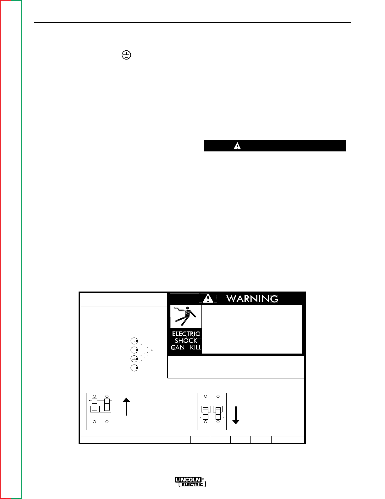
INPUT VOLTAGE RECONNECT
PROCEDURE
When received directly from the factory, units are connected for the highest input voltage, 440 VAC for
50/60 Hz machines and 460 VAC for 60 Hz machines.
If 440 or 460 VAC is the desired input, then the
machine may be connected to the power system without any setup required inside the reconnect door.
However, verify the connection with the following procedure. For other voltages refer to the instructions
located on the Reconnect Panel Access Door or follow the instructions below.
CAUTION
Failure to follow these instructions can cause immediate failure of components within the welder.
------------------------------------------------------------------------
1. Open the access door on the right side of the
machine.
2. For 200-230: Position the large switch to 200-230.
For 380-460: Position the large switch to 380-460.
3. Move the “A” lead to the appropriate terminal.
Refer to figure A.1 below.
• Install the proper fuse in the fuse holder in the main
disconnect panel.
RECONNECT PROCEDURE
1. BE SURE POWER SWITCH IS OFF.
2. CONNECT LEAD 'A' TO DESIRED
INPUT VOLTAGE RANGE.
440-460V
380-415V
220-230V
200-208V
3. POSITION SWITCH TO DESIRED INPUT VOLTAGE RANGE.
VOLTAGE=380-460V
THE LINCOLN ELECTRIC CO. CLEVELAND, OHIO U.S.A.
Figure A.1 Input Voltage Reconnect Instructions
'A'
IF MACHINE CEASES TO OPERATE (NO METER, NO FAN)
AND THERE IS NO OTHER KNOWN FAILURE: CHECK FUSE;
REPLACE WITH SPECIFIED FUSE.
.
Disconnect input power before
inspecting or servicing machine.
.
Do not operate with wraparound
removed.
.
Do not touch electrically live parts.
.
Only qualified persons should install,
use or service this equipment.
VOLTAGE=200-230V
A
S21230
Return to Master TOC Return to Master TOC Return to Master TOC Return to Master TOC
Return to Section TOC Return to Section TOC Return to Section TOC Return to Section TOC
INVERTEC V250-S
A-5
INSTALLATION
A-5
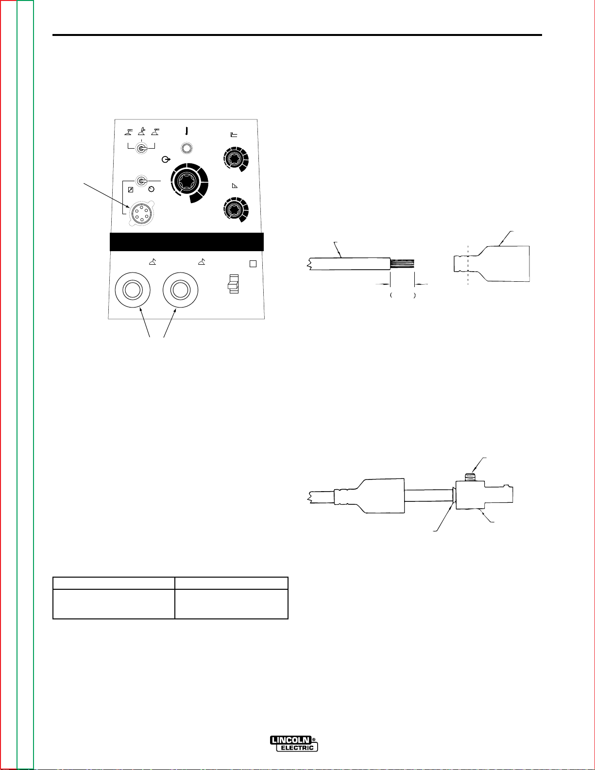
OUTPUT CONNECTIONS
Refer to figure A.2 for the location of the 6 Pin Remote
Receptacle and the Output Terminals.
SMAW
SMAW
6 PIN
REMOTE
RECEPTACLE
SOFT
REMOTE
GTAW
CRISP
LOCAL
-
THERMAL
A
120
85
OUTPUT
50
15
1
250
INVERTEC V250-S
+
HOT START
5
6
4
3
2
1
0
170
ARC FORCE
230
5
6
4
3
2
1
0
¤
I
O
7
8
9
10
7
8
9
10
S
QUICK DISCONNECT PLUGS
A quick disconnect system is used for the welding
cable connections. The welding plug included with the
machine is designed to accept a welding cable size of
1/0 to 2/0.
1. Remove 1 in. (25mm) of welding cable insulation.
2. Slide rubber boot onto cable end. The boot end
may be trimmed to match the cable diameter.
Soap or other lubricant will help to slide the boot
over the cable.
BOOT
WELDING CABLE
25 mm
1 in.
TRIM
OUTPUT TERMINALS
FIGURE A.2 OUTPUT CONNECTIONS
REMOTE CONTROL RECEPTACLE
Remote control (K857), Arc start switch (K814), Hand
amptrol (K963) and Foot amptrol (K870) connect
directly to 6 pin amphenol on the front of the unit.
OUTPUT CABLES
Select the output cable size based on Table A.1.
TABLE A.1
Cable Sizes for Combined Length of Electrode and
Work Cable ( Copper Cable Rated at 75°C).
Length Cable Size
up to 150 ft.(46m) 1/0 (50mm2)
up to 250 ft.(72m) 2/0 (70mm2)
3. Slide the copper tube into the brass plug.
4. Insert cable into copper tube.
5. Tighten set screw to collapse copper tube. Screw
must apply pressure against welding cable. The
top of the set screw will be well below the surface
of the brass plug after tightening.
SET SCREW
BRASS PLUG
COPPER TUBE
6. Slide rubber boot over brass plug. The rubber
boot must be positioned to completely cover all
electrical surfaces after the plug is locked into the
receptacle.
Return to Master TOC Return to Master TOC Return to Master TOC Return to Master TOC
Return to Section TOC Return to Section TOC Return to Section TOC Return to Section TOC
INVERTEC V250-S

A-6
NOTES
A-6
Return to Master TOC Return to Master TOC Return to Master TOC Return to Master TOC
Return to Section TOC Return to Section TOC Return to Section TOC Return to Section TOC
INVERTEC V250-S

OPERATION
SECTION-B-1SECTION-B-1
TABLE OF CONTENTS
-OPERATION SECTION-
SAFETY INSTRUCTIONS ...........................................................................................................B-2
GENERAL DESCRIPTION...........................................................................................................B-2
OPERATIONAL FEATURES.................................................................................................B-2
WELDING CAPABILITY ........................................................................................................B-2
LIMITATIONS ........................................................................................................................B-2
CONTROLS AND SETTINGS......................................................................................................B-3
CONSTANT CURRENT PROCESSES........................................................................................B-4
MANUAL ARC WELDING (STICK)........................................................................................B-4
AIR CARBON ARC CUTTING...............................................................................................B-4
TIG WELDING.......................................................................................................................B-4
PARALLEL OPERATION.............................................................................................................B-5
OVERLOAD PROTECTION.........................................................................................................B-5
THERMAL PROTECTION............................................................................................................B-5
Return to Master TOC Return to Master TOC Return to Master TOC Return to Master TOC
INVERTEC V250-S

B-2
OPERATION
B-2
Read and understand this entire section before
operating your machine.
SAFETY INSTRUCTIONS
WARNING
ELECTRIC SHOCK can kill.
• Do not touch electrically live parts such
as output terminals or internal wiring.
• Insulate yourself from the work and
ground.
• Always wear dry insulating gloves.
____________________________________
FUMES AND GASES
can be dangerous.
• Keep your head out of fumes.
• Use ventilation or exhaust to
remove fumes from breathing
zone.
____________________________________
WELDING, CUTTING and
GOUGING SPARKS
can cause fire or explosion
GENERAL DESCRIPTION
The Invertec V250-S is a 250 amp arc welding power
source that utilizes single or three phase input power,
to produce constant current output. The welding
response of this Invertec has been optimized for stick
(SMAW) and TIG (GTAW).
OPERATIONAL FEATURES
The Invertec V250-S provides continuous total range
output current adjustment, selectable welding modes
and local or remote output control. Welding characteristics can be controlled via an arc force control.
Additionally, starting characteristics can be adjusted
via a “hot start” control.
WELDING CAPABILITY
The Invertec V250-S is rated at 250 amps, 35% duty
cycle (based on a 10 minute cycle). It is also rated at
165 amps, 100% duty cycle, and 200 amps, 60% duty
cycle.
LIMITATIONS
The V250-S is not recommended for pipe thawing.
The V250-S should not be powered from the auxiliary
power supply of an engine welder. Special protection
circuits may operate causing loss of output.
____________________________________
____________________________________
Only qualified personnel should operate this equipment. Observe all safety information throughout this
manual.
Return to Master TOC Return to Master TOC Return to Master TOC Return to Master TOC
Return to Section TOC Return to Section TOC Return to Section TOC Return to Section TOC
• Keep flammable material away.
• Do not weld, cut or gouge on
containers that have held com-
bustibles.
ARC RAYS
can burn.
• Wear eye, ear and body
protection.
INVERTEC V250-S
B-3
OPERATION
B-3
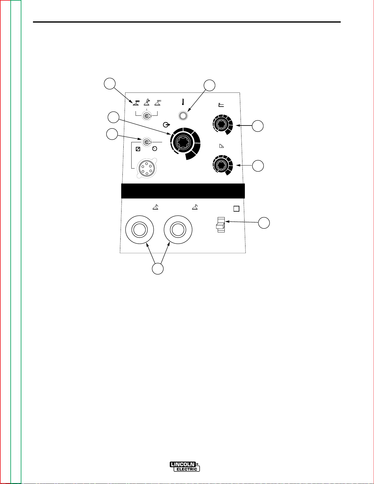
CONTROLS AND SETTINGS
All operator controls and adjustments are located on the case front of the V250-S. Refer to Figure B.1 and corresponding explanations.
FIGURE B.1 — CASE FRONT CONTROLS.
4
SMAW
SOFT
GTAW
SMAW
CRISP
THERMAL
2
A
OUTPUT
3
REMOTE
LOCAL
50
15
120
85
1
INVERTEC V250-S
-
+
250
170
230
8
HOT START
5
6
4
0
ARC FORCE
5
4
0
I
7
8
9
10
6
7
8
9
10
5
6
S
3
2
1
3
2
1
®
1
O
7
1. Power Switch - Place the lever in the “ON” position
to energize the machine. When the power is on, the
fan will operate and the output will be energized in
SMAW modes. GTAW mode requires remote trigger to energize the output.
2. Output Control - This controls the output current.
Control is provided over the entire output range of
the power source with 1 turn of the control knob.
This control may be adjusted while under load to
change power source output. When using remote
control this function becomes the limit setting.
3. Local/Remote Switch - Place in the “LOCAL” position to allow output adjustment at the machine.
Place in the “REMOTE” position to allow output
adjustment at remote pot or amptrol. In Remote, the
machine output control pot is the limit setting for
remote control.
4. Mode Switch
GTAW
Optimized for touch start use. Triggering at
amphenol is required using an Arc Start Switch,
Amptrol or similar means. Short circuit current is
limited to approximately 25 amps to aid in touch
starting.
CC Soft
Best for EXX18 thru EXX28 stick elec-
trodes. Output energized when machine is on.
CC Crisp
Use this mode for stick welding with
EXX10 thru EXX14 electrodes. Output energized
when machine is on.
5. Hot Start - Controls the amount of starting energy
in SMAW.
Return to Master TOC Return to Master TOC Return to Master TOC Return to Master TOC
Return to Section TOC Return to Section TOC Return to Section TOC Return to Section TOC
INVERTEC V250-S

B-4
OPERATION
B-4
6. Arc Force - This control functions in SMAW modes
to adjust the Arc Force. The arc is soft at the minimum settings and more forceful or driving at the
maximum settings. Higher spatter levels may be
present at the maximum settings.
RECOMMENDED ARC FORCE/INDUCTANCE
SETTINGS FOR SELECTED APPLICATIONS
FULL RANGE IS 1-10. 1 is VERY SOFT,
10 IS VERY CRISP
Nominal Recommended
Mode Process Setting Adjustment Range
CC SMAW 1 EXX18 thru 5 1 (gentle, may stick) to 9
(soft) EXX28 stick (forceful, more spatter)
CC SMAW 2 EXX10 thru 6 3 to 10
(crisp) EXX14 stick
Air Carbon Arc 1 None
Cutting
7. Output Terminals - These quick disconnect terminals provide connection points for the electrode and
work cables. Refer to
Installation chapter for proper cable sizes. For
positive polarity welding connect the electrode
cable to the positive terminal and the work cable to
the negative terminal. To weld negative polarity
reverse the electrode and work cables.
Output Connections
in the
CONSTANT CURRENT PROCESSES
MANUAL ARC WELDING (STICK)
The Invertec may be utilized as a manual DC arc
welder with the electrode cable, work cable, and electrode holder being the only equipment required.
AIR CARBON ARC CUTTING
Air carbon arc cutting may be performed with the
Invertec within its output rating using 5/32" (3.9mm)
and 3/16" (4.7mm) diameter carbon rods. Output
cables, an air carbon arc electrode cable assembly,
and a source of compressed air are required.
NOTE:
1. Best performance will be at settings of 200 amps
and below.
2. The electronic protection circuit in the V250S will
limit the current to approximately 290 amps.
TIG WELDING
The V250S is capable of touch start TIG welding. An
electrode cable, work cable, Arc Start Switch or
Amptrol, TIG torch, and gas supply with regulator are
required. Refer to
Touch starting is done as follows:
Accessories
section of this manual.
8. Thermal Shutdown Indicator - This light will illuminate if an internal thermostat has been activated.
Machine output will return after the internal
components have returned to a normal operating
temperature. See
chapter.
Thermal Protection
later in this
1. Place the shield cup edge on the work piece.
2. Rock the tungsten down to touch.
3. Trigger the output.
4. Gently rock back the tungsten from the workpiece.
Note: The short circuit current is limited to 25 amps to
aid in touch starting. Panel output control
becomes the current limit setting when in
remote control
Return to Master TOC Return to Master TOC Return to Master TOC Return to Master TOC
Return to Section TOC Return to Section TOC Return to Section TOC Return to Section TOC
INVERTEC V250-S

B-5
OPERATION
PARALLEL OPERATION
The Invertec’s are operable in parallel. For best
results, the currents of each machine should be reasonably well shared. As an example, with two
machines set up in parallel for a 300 amp procedure,
each machine should be set to deliver approximately
150 amps, not 200 amps from one and 100 amps
from the other. This will minimize nuisance feedback
conditions. In general, more than two machines in parallel will not be effective due to the voltage requirements of procedures in that power range.
To set machine outputs, start with output control pots
and arc force pots in identical positions. Adjust outputs and arc forces to maintain current sharing while
establishing the proper output current.
OVERLOAD PROTECTION
The machine is electrically protected from producing
high output currents. Should the output current
exceed 290A, an electronic protection circuit will
reduce the current to less than 200A. The machine
will continue to produce this low current until the protection circuit is reset. Reset occurs when the output
load is removed.
B-5
THERMAL PROTECTION
Thermostats protect the machine from excessive
operating temperatures. Excessive temperatures may
be caused by a lack of cooling air or operating the
machine beyond the duty cycle and output rating. If
excessive operating temperature should occur, the
thermostats will prevent output voltage or current.
Thermostats are self-resetting once the machine cools
sufficiently. If the thermostat shutdown was caused by
excessive output or duty cycle and the fan is operating
normally, the Power Switch may be left on and the
reset should occur within a 15 minute period. If the fan
is not turning or the air intake louvers were obstructed,
then the power must be switched off for 15 minutes in
order to reset. The fan problem or air obstruction must
also be corrected.
Return to Master TOC Return to Master TOC Return to Master TOC Return to Master TOC
Return to Section TOC Return to Section TOC Return to Section TOC Return to Section TOC
INVERTEC V250-S

B-6
NOTES
B-6
Return to Master TOC Return to Master TOC Return to Master TOC Return to Master TOC
Return to Section TOC Return to Section TOC Return to Section TOC Return to Section TOC
INVERTEC V250-S

SECTION C-1
OPTIONS / ACCESSORIES........................................................................................................C-2
CABLE PLUGS......................................................................................................................C-2
REMOTE CONTROLS ..........................................................................................................C-2
ACCESSORIES
SECTION C-1
TABLE OF CONTENTS
-ACCESSORIES SECTION-
K852-70 .......................................................................................................................C-2
K852-95 .......................................................................................................................C-2
K857.............................................................................................................................C-2
K963 ............................................................................................................................C-2
K870.............................................................................................................................C-2
K814 ............................................................................................................................C-2
Return to Master TOC Return to Master TOC Return to Master TOC Return to Master TOC
INVERTEC V250-S

C-2
ACCESSORIES
OPTIONS / ACCESSORIES
CABLE PLUGS
K852-70 - Cable Plug Kit for 1/0-2/0 cable. Attaches
to welding cable to provide quick disconnect from
machine.
K852-95 - Cable Plug Kit for 2.0-3/0 cable.
NOTE: Two K852-70 plugs are included with the
V250-S.
REMOTE CONTROLS
K857 - Remote Output Control for stick welding.
K963 - Hand Amptroltmfor TIG welding. When the
V250-S’s Output Control is in the “Remote” position,
the hand Amptrol energizes the output and controls
the output remotely. The Hand Amptrol connects
directly to the 6 pin Amphenol.
C-2
K870 - Foot Amptroltmfor TIG welding. When the
V250-S’s Output Control is in the “REMOTE” position,
the foot Amptrol energizes the output and controls the
output remotely. The Hand Amptrol connects directly
to the 6 pin Amphenol.
K814 - Arc Start Switch. Energizes the output for TIG
welding if remote output control of the amperage is
not desired. When using the Arc Start Switch set the
Output Control to the “LOCAL” position.
Return to Master TOC Return to Master TOC Return to Master TOC Return to Master TOC
Return to Section TOC Return to Section TOC Return to Section TOC Return to Section TOC
INVERTEC V250-S

SECTION D-1
INPUT FILTER CAPACITOR DISCHARGE PROCEDURE.........................................................D-2
ROUTINE MAINTENANCE..........................................................................................................D-3
FILTER CAPACITOR CONDITIONING ......................................................................................D-3
LOCATION OF MAINTENANCE COMPONENTS.......................................................................D-4
MAINTENANCE
TABLE OF CONTENTS
-MAINTENANCE SECTION-
SECTION D-1
Return to Master TOC Return to Master TOC Return to Master TOC Return to Master TOC
INVERTEC V250-S
D-2
MAINTENANCE
D-2
WARNING
ELECTRIC SHOCK can kill.
• Have an electrician install and service
this equipment.
• Turn the input power off at the fuse
box before working on equipment.
• Do not touch electrically hot parts.
• Prior to Performing preventative maintenance, perform the following capacitor discharge procedure to avoid electric shock.
---------------------------------------------------------------------
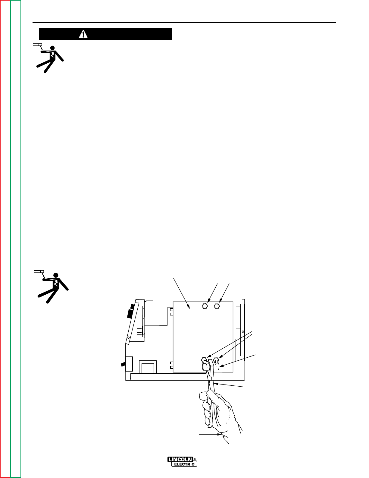
INPUT FILTER CAPACITOR
DISCHARGE PROCEDURE
1. Turn off input power or disconnect input power
lines.
2. Remove the 5/16" hex head screws from the side
and top of the machine and remove wrap-around
machine cover.
3. Be careful not to make contact with the capacitor
terminals that are located in the top and bottom of
the Power Board.
4. Obtain a high resistance and high wattage resistor
(25-1000 ohms and 25 watts minimum). This resistor is not supplied with machine. NEVER USE A
SHORTING STRAP FOR THIS PROCEDURE.
5. Locate the four capacitor terminals (large hex head
cap screws) shown in Figure D.1. One pair at the
top and one pair at the bottom of the Power Board.
6. Use electrically insulated gloves and insulated pliers. Hold body of the resistor and connect resistor
leads across the two capacitor terminals. Hold
resistor in place for 10 seconds. DO NOT TOUCH
CAPACITOR TERMINALS WITH YOUR BARE
HANDS.
7. Repeat discharge procedure for the capacitor on
other two terminals.
8. Check voltage across terminals of all capacitors
with a DC voltmeter. Polarity of capacitor terminals
is marked on PC board above terminals. Voltage
should be zero. If any voltage remains, repeat this
capacitor discharge procedure.
FIGURE D.1 — LOCATION OF INPUT FILTER CAPACITOR TERMINALS.
POWER
BOARD
RIGHT SIDE OF MACHINE
CAP ACIT OR TERMINALS
UPPER
LOWER
CAPACITOR
TERMINALS
POWER
RESISTOR
INSULATED
PLIERS
Return to Master TOC Return to Master TOC Return to Master TOC Return to Master TOC
Return to Section TOC Return to Section TOC Return to Section TOC Return to Section TOC
INSULATED
GLOVES
INVERTEC V250-S

D-3
MAINTENANCE
D-3
ROUTINE MAINTENANCE
1. Perform the following preventive maintenance
procedures at least once every six months. It is
good practice to keep a preventive maintenance
record; a record tag attached to the machine
works best.
2. Remove the machine wrap-around cover and perform the input filter capacitor discharge procedure
(detail at the beginning of this chapter).
3. Keeping the machine clean will result in cooler
operation and higher reliability. Be sure to clean
the following areas with a low pressure air
stream. See figure D.2 for component locations.
• Power and control printed circuit boards
• Power switch
• Main transformer
• Input rectifier
• Heat sink fins
• Input Filter Capacitors
• Output Terminals
FILTER CAPACITOR
CONDITIONING
A protection circuit is included to monitor the voltage
across filter capacitors C1 and C2. In the event that
the capacitor voltage is too high, the protection circuit
will prevent output. Nominal trip setting is at 230/460
VAC +15%. Reset occurs about 3% lower (230/460
VAC +12%).
On new installations, the protection circuit may also
prevent output providing all these circumstances are
met:
1. Machine is connected for 380-415 or 440-460
VAC input.
2. Machine did not have power applied for many
months.
3. Machine will not produce output when power is
first switched on.
If these circumstances apply, the proper action is to
switch the machine on and let it idle for up to 30 minutes. This is required to condition the filter capacitors
after an extended storage time. The protection circuit
will automatically reset once the capacitor conditioning
and resultant voltage levels are acceptable. It may be
necessary to turn the power switch off and back on
again after this period.
4. Examine capacitors for leakage or oozing. Replace
if needed.
5. Examine the sheet metal case for dents or break-
age. Repair the case as required. Keep the case
in good condition to ensure that high voltage
parts are protected and correct spacings are
maintained. All external sheet metal screws must
be in place to assure case strength and electrical
ground continuity.
6. Check electrical ground continuity. Using an ohmmeter, measure resistance between either output
terminal and an unpainted surface of the machine
case. (See Figure D.2 for locations.) Meter reading
should be 500,000 ohms or more. If meter reading
is less than 500,000 ohms, check for electrical
components that are not properly insulated from
the case. Correct insulation if needed.
7. Replace machine cover and screws.
Return to Master TOC Return to Master TOC Return to Master TOC Return to Master TOC
Return to Section TOC Return to Section TOC Return to Section TOC Return to Section TOC
INVERTEC V250-S
D-4
MAINTENANCE
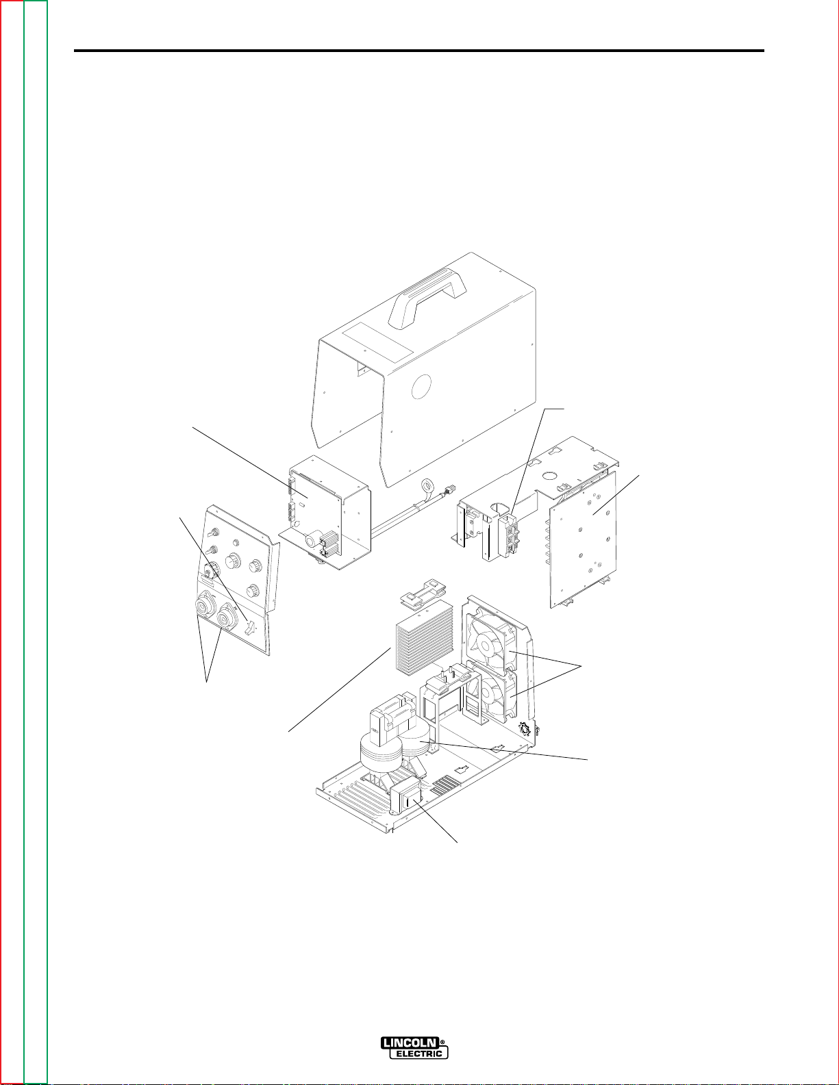
FIGURE D.2 — LOCATION OF MAINTENANCE COMPONENTS.
D-4
CONTROL PC BOARD
POWER SWITCH
OUTPUT TERMINALS
OUTPUT RECTIFIER
HEATSINK FINS
INPUT RECTIFIER
POWER PC BOARD
COOLING FANS
MAIN TRANSFORMER
Return to Master TOC Return to Master TOC Return to Master TOC Return to Master TOC
Return to Section TOC Return to Section TOC Return to Section TOC Return to Section TOC
AUXILIARY TRANSFORMER
INVERTEC V250-S

E-1
THEORY OF OPERATION
TABLE OF CONTENTS
-THEORY OF OPERATION SECTION-
GENERAL DESCRIPTION...........................................................................................................E-2
INPUT LINE VOLTAGE................................................................................................................E-2
PRE-CHARGE AND PROTECTION............................................................................................E-3
MAIN TRANSFORMER................................................................................................................E-4
OUTPUT RECTIFICATION AND CONTROL...............................................................................E-5
PROTECTION CIRCUITS............................................................................................................E-6
INSULATED GATE BIPOLAR TRANSISTOR (IGBT) OPERATION............................................E-7
PULSE WIDTH MODULATION (PWM)........................................................................................E-8
E-1
Return to Master TOC Return to Master TOC Return to Master TOC Return to Master TOC
INVERTEC V250-S
E-2
THEORY OF OPERATION
E-2
GENERAL DESCRIPTION
The Invertec V250-S is a 250 amp arc welding power source that utilizes either single or three phase input power
to produce a constant current output. The output response of this machine has been optimized for the SMAW
and TIG welding processes.
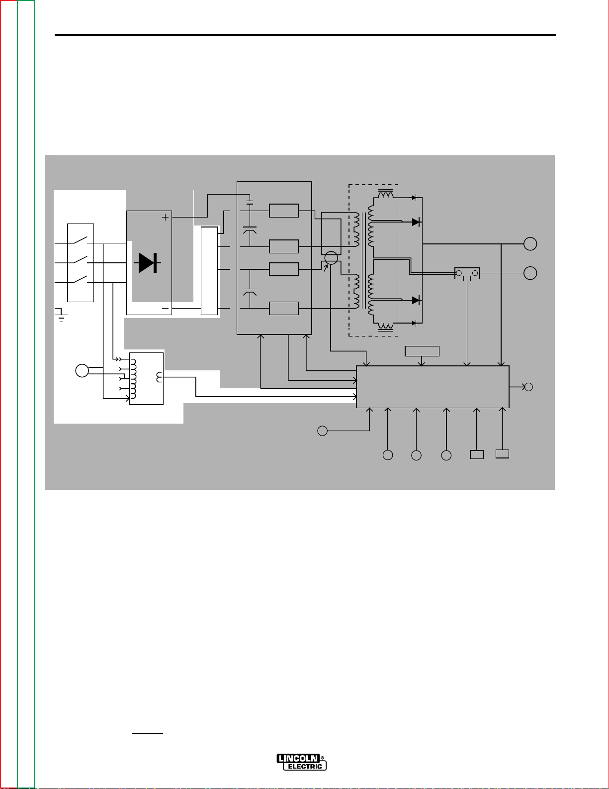
FIGURE E.1 - INPUT VOLTAGE CIRCUITS
INPUT
LINE
SWITCH
FAN
MOTORS
INPUT
RECTIFIER
A"
"
L
E
A
D
AUXILIARY
TRANSFORMER
R
E
C
O
N
N
E
C
T
S
W
I
T
C
H
18VAC
POWER BOARD
CR1
RELAY
IGBT
CAPACITOR
IGBT
IGBT
CAPACITOR
IGBT
O
V
E
R
V
O
L
T
A
G
E
PROTECTION SIGNAL
CR1 RELAY DRIVE SIGNAL
CURRENT
TRANSFORMER
GATE SIGNALS
IGBT
REMOTE
RECEPTACLE
MAIN
TRANSFORMER
CONTROL BOARD
OUTPUT
CONTROL
THERMOSTATS
STRIKE
CONTROL
SHUNT
ARC
FORCE
CONTROL
F
E
E
D
B
A
C
K
MODE
SWITCH
F
E
E
D
B
A
C
K
LOCAL/
REMOTE
SWITCH
POSITIVE
OUTPUT
TERMINAL
NEGATIVE
OUTPUT
TERMINAL
THERMAL
LIGHT
INPUT LINE VOLTAGE
The single-phase or three-phase input power of 208,
230 or 460 volts AC is connected to the machine,
through a line switch located on the front panel.
A reconnect panel and switch allows the user to configure the machine for either a low or high input voltage and also connect the auxiliary transformer for the
appropriate input voltage.
The auxiliary transformer develops the appropriate AC
voltages to operate the cooling fans and the control
board.
Return to Master TOC Return to Master TOC Return to Master TOC Return to Master TOC
Return to Section TOC Return to Section TOC Return to Section TOC Return to Section TOC
NOTE: Unshaded areas of block logic diagrams are the subject of discussion.
INVERTEC V250-S
E-3
THEORY OF OPERATION
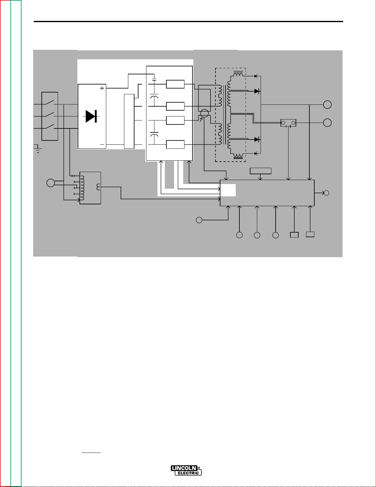
FIGURE E.2 PROTECTION AND PRE-CHARGE CIRCUITS
E-3
INPUT
LINE
SWITCH
FAN
MOTORS
INPUT
RECTIFIER
A"
"
L
E
A
D
AUXILIARY
TRANSFORMER
R
E
C
O
N
N
E
C
T
S
W
I
T
C
H
18VAC
POWER BOARD
CR1
RELAY
IGBT
CAPACITOR
IGBT
IGBT
CAPACITOR
IGBT
O
V
E
R
V
O
L
T
A
G
E
PROTECTION SIGNAL
CR1 RELAY DRIVE SIGNAL
CURRENT
TRANSFORMER
GATE SIGNALS
IGBT
REMOTE
RECEPTACLE
MAIN
TRANSFORMER
CONTROL BOARD
OUTPUT
CONTROL
THERMOSTATS
STRIKE
CONTROL
SHUNT
ARC
FORCE
CONTROL
F
E
E
D
B
A
C
K
MODE
SWITCH
F
E
E
D
B
A
C
K
LOCAL/
REMOTE
SWITCH
POSITIVE
OUTPUT
TERMINAL
NEGATIVE
OUTPUT
TERMINAL
THERMAL
LIGHT
PRECHARGE AND PROTECTION
The input voltage is rectified and the DC voltage is
applied, through the reconnect switch, to the power
board. The power board contains precharging circuitry for the safe charging of the input filter capacitors.
Once the capacitors are precharged and balanced the
control board activates the CR1 input relay which connects full input power to the filter capacitors. When
the filter capacitors are fully charged they act as
power supplies for the IGBT switching circuit. The
Insulated Gate Bipolar Transistors supply the main
transformer primary windings with DC current flow.
See
IGBT Operation Discussion and diagrams
this section.
The power board also monitors the filter capacitors for
voltage balance and/or overvoltage and, if either
should occur, sends the appropriate signal to the control board to deactivate the CR1 input relay. The
machine output will also be disabled.
in
Return to Master TOC Return to Master TOC Return to Master TOC Return to Master TOC
Return to Section TOC Return to Section TOC Return to Section TOC Return to Section TOC
NOTE: Unshaded areas of block logic diagrams are the subject of discussion.
INVERTEC V250-S
E-4
THEORY OF OPERATION
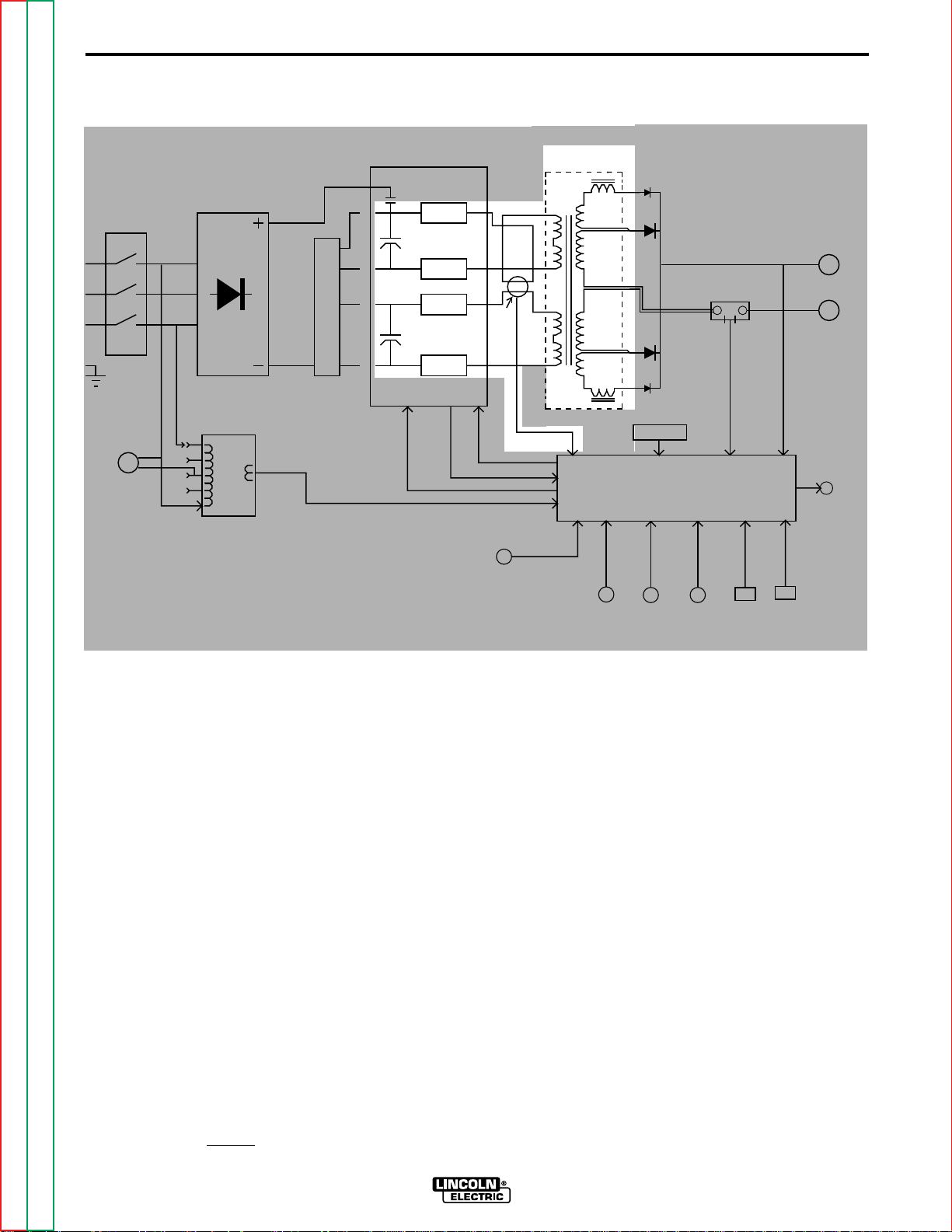
FIGURE E.3 MAIN TRANSFORMER
E-4
INPUT
LINE
SWITCH
FAN
MOTORS
INPUT
RECTIFIER
A"
"
L
E
A
D
AUXILIARY
TRANSFORMER
R
E
C
O
N
N
E
C
T
S
W
I
T
C
H
18VAC
POWER BOARD
CR1
RELAY
IGBT
CAPACITOR
IGBT
IGBT
CAPACITOR
IGBT
O
V
E
R
V
O
L
T
A
G
E
PROTECTION SIGNAL
CR1 RELAY DRIVE SIGNAL
CURRENT
TRANSFORMER
GATE SIGNALS
IGBT
REMOTE
RECEPTACLE
MAIN
TRANSFORMER
CONTROL BOARD
OUTPUT
CONTROL
THERMOSTATS
STRIKE
CONTROL
SHUNT
ARC
FORCE
CONTROL
F
E
E
D
B
A
C
K
MODE
SWITCH
F
E
E
D
B
A
C
K
LOCAL/
REMOTE
SWITCH
POSITIVE
OUTPUT
TERMINAL
NEGATIVE
OUTPUT
TERMINAL
THERMAL
LIGHT
MAIN TRANSFORMER
Each IGBT pair acts as a switch assembly. Each
assembly feeds a separate, oppositely wound primary
winding of the main transformer. The reverse directions of current flow through the main transformer primaries and the offset timing of the IGBT pairs induce
an AC square wave output signal at the secondary of
the main transformer.
The DC current flow through each primary winding is
redirected or “clamped” back to each respective filter
capacitor when the IGBTs are turned off. This is
needed due to the inductance of the transformer primary winding.
The primary currents also pass through the current
transformer which sends a signal to the control board.
If the primary currents are not equal the control board
compensates by adjusting the IGBT gate signals.
The firing of both IGBT pairs occurs during halves of
the 50 microsecond intervals, creating a constant 20
KHZ output.
Return to Master TOC Return to Master TOC Return to Master TOC Return to Master TOC
Return to Section TOC Return to Section TOC Return to Section TOC Return to Section TOC
NOTE: Unshaded areas of block logic diagrams are the subject of discussion.
INVERTEC V250-S
E-5
THEORY OF OPERATION
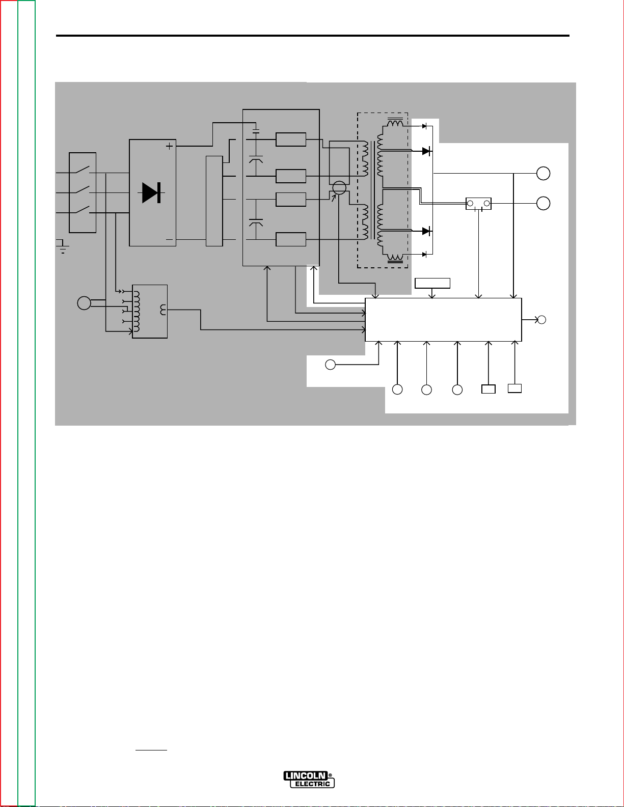
FIGURE E.4 OUTPUT RECTIFICATION AND CONTROL
E-5
INPUT
LINE
SWITCH
FAN
MOTORS
INPUT
RECTIFIER
A"
"
L
E
A
D
AUXILIARY
TRANSFORMER
R
E
C
O
N
N
E
C
T
S
W
I
T
C
H
18VAC
POWER BOARD
CR1
RELAY
IGBT
CAPACITOR
IGBT
IGBT
CAPACITOR
IGBT
O
V
E
R
V
O
L
T
A
G
E
PROTECTION SIGNAL
CR1 RELAY DRIVE SIGNAL
CURRENT
TRANSFORMER
GATE SIGNALS
IGBT
REMOTE
RECEPTACLE
MAIN
TRANSFORMER
CONTROL BOARD
OUTPUT
CONTROL
THERMOSTATS
STRIKE
CONTROL
SHUNT
ARC
FORCE
CONTROL
F
E
E
D
B
A
C
K
MODE
SWITCH
F
E
E
D
B
A
C
K
LOCAL/
REMOTE
SWITCH
POSITIVE
OUTPUT
TERMINAL
NEGATIVE
OUTPUT
TERMINAL
THERMAL
LIGHT
OUTPUT RECTIFICATION
AND CONTROL
The AC output from the main transformer secondary
is rectified to a DC output and applied to the output
terminals. Output voltage and current feedback information, which is fed to the control board, is sensed at
the output terminals and shunt. The control board
monitors the panel controls and remote control receptacle and compares these commands to the feedback
information to determine how the output should be
controlled to optimized welding results. The control
board controls the IGBT switching through pulse width
modulation circuitry. See
in this section.
IGBT Operation
Discussion
Return to Master TOC Return to Master TOC Return to Master TOC Return to Master TOC
Return to Section TOC Return to Section TOC Return to Section TOC Return to Section TOC
NOTE: Unshaded areas of block logic diagrams are the subject of discussion.
INVERTEC V250-S

E-6
THEORY OF OPERATION
PROTECTION CIRCUITS
Protective circuits are designed into the V250-S
machine to sense trouble and shut down the machine
before the trouble damages the internal machine components. Both overload and thermal protection circuits are included.
E-6
OVERLOAD PROTECTION
The V250-S is electrically protected from producing
high output currents. Should the output current
exceed 290 amps, an electronic protection circuit will
reduce the current to less than 200 amps. Lincoln
Electric refers to this current reduction as “Fold Back”.
The machine will continue to produce this low current
until the protection circuit is reset. Reset occurs when
the output load is removed.
A protection circuit is included to monitor the voltage
across the input filter capacitors. In the event that the
capacitor voltage is too high, the protection circuit will
prevent output.
On new installations, the protection circuit may prevent output, due to unbalanced capacitor leakages,
providing the following circumstances are met:
1. Machine is connected for 380 - 460VAC input.
2. Machine did not have power applied for many
months.
3. Improper connections.
THERMAL PROTECTION
Thermostats protect the machine from excessive
operating temperatures. Excessive temperatures may
be caused by a lack of cooling air or operating the
machine beyond the duty cycle and output rating. If
excessive operating temperature should occur, the
thermostat will prevent output voltage or current and
the thermal indicator light will glow.
Thermostats are self-resetting once the machine cools
sufficiently. If the thermostat shutdown was caused
be excessive output or duty cycle and the fan is operating normally, the power switch may be left on and
the reset should occur within 15 minute period. If the
fan is not turning or the air intake louvers were
obstructed, then the power must be switched off for 15
minutes in order to reset. The fan problem or air
obstruction must be corrected.
4. Internal component damage.
Return to Master TOC Return to Master TOC Return to Master TOC Return to Master TOC
Return to Section TOC Return to Section TOC Return to Section TOC Return to Section TOC
NOTE: Unshaded areas of block logic diagrams are the subject of discussion.
INVERTEC V250-S
Loading...