


Return to Master TOC |
View Safety Info |
Return to Master TOC |
View Safety Info |
Return to Master TOC |
View Safety Info |
Return to Master TOC |
View Safety Info |
RETURN TO MAIN INDEX |
SVM158-A |
|
|
|
April, 2002 |
INVERTEC V350-PRO
For use with machine code numbers 10873, 10874, 10876
! |
WA |
|
|
|
! |
RNING |
|
|
|
W |
|
|
|
|
ARNING |
|
|
||
|
|
|
! |
A |
|
|
! |
|
|
Safety Depends on You |
|
|
A |
TTENTIONDE |
|
|
VISO |
||
|
PRECAUCION |
|||
|
|
|
|
|
Lincoln arc welding and cutting equipment is designed and built with safety in mind. However, your overall safety can be increased by proper installation
. . . and thoughtful operation on your part. DO NOT INSTALL,
OPERATE OR REPAIR THIS EQUIPMENT WITHOUT READING THIS MANUAL AND THE SAFETY PRECAUTIONS CONTAINED THROUGHOUT. And, most importantly, think before you act and be careful.
CC- |
|
|
|
STICK |
7018 |
CC- |
||
TIG |
STICK |
6010 |
CV-GTAW |
|
|
|
WIRE |
|
CV- |
|
|
|
FLUX |
CORED |
|
|
|
A |
AMPS |
|
|
|
|
|
|
|
|
|
|
|
|
A |
|
|
|
|
|
OUTPUT |
|
||
|
|
HOT |
START |
|
|
|
|
4 |
5 |
|
|
SELECT |
3 |
|
|
||
2 |
|
6 |
|
||
|
|
1 |
|
|
7 |
|
|
0 |
|
|
8 |
|
|
|
|
10 |
9 |
|
|
|
|
|
|
V |
VOLTS |
|
|
|
|
||
WELD |
T |
|
|
ERMINALS |
|||
|
|||
SELECT |
|
||
ARC |
|
|
|
-2CONTROL |
|
||
-4 |
0 |
|
|
-6 |
+2 |
|
|
-8 |
|
+4 |
|
-10 |
|
+6 |
|
|
|
||
SOFT |
+10 |
+8 |
|
|
CRISP |
||
SERVICE MANUAL
Copyright © 2002 Lincoln Global Inc.
•World's Leader in Welding and Cutting Products •
•Sales and Service through Subsidiaries and Distributors Worldwide •
Cleveland, Ohio 44117-1199 U.S.A. TEL: 216.481.8100 FAX: 216.486.1751 WEB SITE: www.lincolnelectric.com
Return to Master TOC
Return to Master TOC
Return to Master TOC
Return to Master TOC
i |
|
SAFETY |
|
i |
|
|
|
|
|
|
|
|
|
|
 WARNING
CALIFORNIA PROPOSITION 65 WARNINGS
Diesel engine exhaust and some of its constituents |
|
The engine exhaust from this product contains |
are known to the State of California to cause can- |
|
chemicals known to the State of California to cause |
cer, birth defects, and other reproductive harm. |
|
cancer, birth defects, or other reproductive harm. |
|
|
|
The Above For Diesel Engines |
|
The Above For Gasoline Engines |
ARC WELDING CAN BE HAZARDOUS. PROTECT YOURSELF AND OTHERS FROM POSSIBLE SERIOUS INJURY OR DEATH. KEEP CHILDREN AWAY. PACEMAKER WEARERS SHOULD CONSULT WITH THEIR DOCTOR BEFORE OPERATING.
Read and understand the following safety highlights. For additional safety information, it is strongly recommended that you purchase a copy of “Safety in Welding & Cutting - ANSI Standard Z49.1” from the American Welding Society, P.O. Box 351040, Miami, Florida 33135 or CSA Standard W117.2-1974. A Free copy of “Arc Welding Safety” booklet E205 is available from the Lincoln Electric Company, 22801 St. Clair Avenue, Cleveland, Ohio 44117-1199.
BE SURE THAT ALL INSTALLATION, OPERATION, MAINTENANCE AND REPAIR PROCEDURES ARE PERFORMED ONLY BY QUALIFIED INDIVIDUALS.
FOR ENGINE powered equipment.
1.a. Turn the engine off before troubleshooting and maintenance work unless the maintenance work requires it to be running.
____________________________________________________
1.b. Operate engines in open, well-ventilated
areas or vent the engine exhaust fumes outdoors.
____________________________________________________
1.c. Do not add the fuel near an open flame welding arc or when the engine is running. Stop the engine and allow it to cool before refueling to prevent spilled fuel from vaporizing on contact with hot engine parts and igniting. Do not spill fuel when filling tank. If fuel is spilled, wipe it up and do not start engine until fumes
have been eliminated.
____________________________________________________
1.d. Keep all equipment safety guards, covers and devices in position and in good repair.Keep hands, hair, clothing and tools away from V-belts, gears, fans and all other moving parts when starting, operating or repairing equipment.
____________________________________________________
1.e. In some cases it may be necessary to remove safety guards to perform required maintenance. Remove guards only when necessary and replace them when the maintenance requiring their removal is complete.
Always use the greatest care when working near moving parts.
___________________________________________________
1.f. Do not put your hands near the engine fan.
Do not attempt to override the governor or idler by pushing on the throttle control rods while the engine is running.
___________________________________________________
1.g. To prevent accidentally starting gasoline engines while turning the engine or welding generator during maintenance work, disconnect the spark plug wires, distributor cap or magneto wire as appropriate.
1.h. To avoid scalding, do not remove the radiator pressure cap when the engine is hot.
ELECTRIC AND MAGNETIC FIELDS may be dangerous
2.a. Electric current flowing through any conductor causes localized Electric and Magnetic Fields (EMF). Welding current creates EMF fields around welding cables and welding machines
2.b. EMF fields may interfere with some pacemakers, and welders having a pacemaker should consult their physician before welding.
2.c. Exposure to EMF fields in welding may have other health effects which are now not known.
2.d. All welders should use the following procedures in order to minimize exposure to EMF fields from the welding circuit:
2.d.1. Route the electrode and work cables together - Secure them with tape when possible.
2.d.2. Never coil the electrode lead around your body.
2.d.3. Do not place your body between the electrode and work cables. If the electrode cable is on your right side, the work cable should also be on your right side.
2.d.4. Connect the work cable to the workpiece as close as possible to the area being welded.
2.d.5. Do not work next to welding power source.
Mar ‘95
Return to Master TOC
Return to Master TOC
Return to Master TOC
Return to Master TOC
ii |
|
SAFETY |
|
ii |
|
|
|
|
|
|
|
|
|
|
ELECTRIC SHOCK can kill.
3.a. The electrode and work (or ground) circuits are electrically “hot” when the welder is on. Do not touch these “hot” parts with your bare skin or wet clothing. Wear dry, hole-free gloves to insulate hands.
3.b. Insulate yourself from work and ground using dry insulation. Make certain the insulation is large enough to cover your full area of physical contact with work and ground.
In addition to the normal safety precautions, if welding must be performed under electrically hazardous conditions (in damp locations or while wearing wet clothing; on metal structures such as floors, gratings or scaffolds; when in cramped positions such as sitting, kneeling or lying, if there is a high risk of unavoidable or accidental contact with the workpiece or ground) use the following equipment:
•Semiautomatic DC Constant Voltage (Wire) Welder.
•DC Manual (Stick) Welder.
•AC Welder with Reduced Voltage Control.
3.c. In semiautomatic or automatic wire welding, the electrode, electrode reel, welding head, nozzle or semiautomatic welding gun are also electrically “hot”.
3.d. Always be sure the work cable makes a good electrical connection with the metal being welded. The connection should be as close as possible to the area being welded.
3.e. Ground the work or metal to be welded to a good electrical (earth) ground.
3.f. Maintain the electrode holder, work clamp, welding cable and welding machine in good, safe operating condition. Replace damaged insulation.
3.g. Never dip the electrode in water for cooling.
3.h. Never simultaneously touch electrically “hot” parts of electrode holders connected to two welders because voltage between the two can be the total of the open circuit voltage of both welders.
3.i. When working above floor level, use a safety belt to protect yourself from a fall should you get a shock.
3.j. Also see Items 6.c. and 8.
ARC RAYS can burn.
4.a. Use a shield with the proper filter and cover plates to protect your eyes from sparks and the rays of the arc when welding or observing open arc welding. Headshield and filter lens should conform to ANSI Z87. I standards.
4.b. Use suitable clothing made from durable flame-resistant material to protect your skin and that of your helpers from the arc rays.
4.c. Protect other nearby personnel with suitable, non-flammable screening and/or warn them not to watch the arc nor expose themselves to the arc rays or to hot spatter or metal.
FUMES AND GASES
can be dangerous.
5.a. Welding may produce fumes and gases
hazardous to health. Avoid breathing these fumes and gases.When welding, keep your head out of the fume. Use enough ventilation and/or exhaust at the arc to keep
fumes and gases away from the breathing zone. When welding with electrodes which require special ventilation such as stainless or hard facing (see instructions on container or MSDS) or on lead or cadmium plated steel and other metals or coatings which produce highly toxic fumes, keep exposure as low as possible and below Threshold Limit Values (TLV) using local exhaust or mechanical ventilation. In confined spaces or in some circumstances, outdoors, a respirator may be required. Additional precautions are also required when welding on galvanized steel.
5.b. Do not weld in locations near chlorinated hydrocarbon vapors coming from degreasing, cleaning or spraying operations. The heat and rays of the arc can react with solvent vapors to form phosgene, a highly toxic gas, and other irritating products.
5.c. Shielding gases used for arc welding can displace air and cause injury or death. Always use enough ventilation, especially in confined areas, to insure breathing air is safe.
5.d. Read and understand the manufacturer’s instructions for this equipment and the consumables to be used, including the material safety data sheet (MSDS) and follow your employer’s safety practices. MSDS forms are available from your welding distributor or from the manufacturer.
5.e. Also see item 1.b. |
Mar ‘95 |
|
Return to Master TOC
Return to Master TOC
Return to Master TOC
Return to Master TOC
iii |
iii |
SAFETY
 WELDING SPARKS can

 cause fire or explosion.
6.a. Remove fire hazards from the welding area. If this is not possible, cover them to prevent the welding sparks from starting a fire.
Remember that welding sparks and hot materials from welding can easily go through small cracks and openings to adjacent areas. Avoid welding near hydraulic lines. Have a fire extinguisher readily available.
6.b. Where compressed gases are to be used at the job site, special precautions should be used to prevent hazardous situations. Refer to “Safety in Welding and Cutting” (ANSI Standard Z49.1) and the operating information for the equipment being used.
6.c. When not welding, make certain no part of the electrode circuit is touching the work or ground. Accidental contact can cause overheating and create a fire hazard.
6.d. Do not heat, cut or weld tanks, drums or containers until the proper steps have been taken to insure that such procedures will not cause flammable or toxic vapors from substances inside. They can cause an explosion even though they have been “cleaned”. For information, purchase “Recommended Safe Practices for the Preparation for Welding and Cutting of Containers and Piping That Have Held Hazardous
Substances”, AWS F4.1 from the American Welding Society
(see address above).
6.e. Vent hollow castings or containers before heating, cutting or welding. They may explode.
6.f. Sparks and spatter are thrown from the welding arc. Wear oil free protective garments such as leather gloves, heavy shirt, cuffless trousers, high shoes and a cap over your hair. Wear ear plugs when welding out of position or in confined places. Always wear safety glasses with side shields when in a welding area.
6.g. Connect the work cable to the work as close to the welding area as practical. Work cables connected to the building framework or other locations away from the welding area increase the possibility of the welding current passing through lifting chains, crane cables or other alternate circuits. This can create fire hazards or overheat lifting chains or cables until they fail.
6.h. Also see item 1.c.
CYLINDER may explode


 if damaged.
7.a. Use only compressed gas cylinders
containing the correct shielding gas for the process used and properly operating regulators designed for the gas and
pressure used. All hoses, fittings, etc. should be suitable for the application and maintained in good condition.
7.b. Always keep cylinders in an upright position securely chained to an undercarriage or fixed support.
7.c. Cylinders should be located:
•Away from areas where they may be struck or subjected to physical damage.
•A safe distance from arc welding or cutting operations and any other source of heat, sparks, or flame.
7.d. Never allow the electrode, electrode holder or any other electrically “hot” parts to touch a cylinder.
7.e. Keep your head and face away from the cylinder valve outlet when opening the cylinder valve.
7.f. Valve protection caps should always be in place and hand tight except when the cylinder is in use or connected for use.
7.g. Read and follow the instructions on compressed gas cylinders, associated equipment, and CGA publication P-l, “Precautions for Safe Handling of Compressed Gases in
Cylinders,” available from the Compressed Gas Association 1235 Jefferson Davis Highway, Arlington, VA 22202.
FOR ELECTRICALLY powered equipment.
8.a. Turn off input power using the disconnect switch at the fuse box before working on the equipment.
8.b. Install equipment in accordance with the U.S. National Electrical Code, all local codes and the manufacturer’s recommendations.
8.c. Ground the equipment in accordance with the U.S. National Electrical Code and the manufacturer’s recommendations.
Mar ‘95
V350-PRO

Return to Master TOC
Return to Master TOC
Return to Master TOC
Return to Master TOC
iv |
iv |
SAFETY
PRÉCAUTIONS DE SÛRETÉ
Pour votre propre protection lire et observer toutes les instructions et les précautions de sûreté specifiques qui parraissent dans ce manuel aussi bien que les précautions de sûreté générales suivantes:
Sûreté Pour Soudage A L’Arc
1.Protegez-vous contre la secousse électrique:
a.Les circuits à l’électrode et à la piéce sont sous tension quand la machine à souder est en marche. Eviter toujours tout contact entre les parties sous tension et la peau nue ou les vétements mouillés. Porter des gants secs et sans trous pour isoler les mains.
b.Faire trés attention de bien s’isoler de la masse quand on soude dans des endroits humides, ou sur un plancher metallique ou des grilles metalliques, principalement dans
les positions assis ou couché pour lesquelles une grande partie du corps peut être en contact avec la masse.
c.Maintenir le porte-électrode, la pince de masse, le câble de
soudage et la machine à souder en bon et sûr état defonctionnement.
d.Ne jamais plonger le porte-électrode dans l’eau pour le refroidir.
e.Ne jamais toucher simultanément les parties sous tension des porte-électrodes connectés à deux machines à souder parce que la tension entre les deux pinces peut être le total de la tension à vide des deux machines.
f.Si on utilise la machine à souder comme une source de courant pour soudage semi-automatique, ces precautions pour le porte-électrode s’applicuent aussi au pistolet de soudage.
2.Dans le cas de travail au dessus du niveau du sol, se protéger contre les chutes dans le cas ou on recoit un choc. Ne jamais enrouler le câble-électrode autour de n’importe quelle partie du corps.
3.Un coup d’arc peut être plus sévère qu’un coup de soliel, donc:
a.Utiliser un bon masque avec un verre filtrant approprié ainsi qu’un verre blanc afin de se protéger les yeux du rayonnement de l’arc et des projections quand on soude ou quand on regarde l’arc.
b.Porter des vêtements convenables afin de protéger la peau de soudeur et des aides contre le rayonnement de l‘arc.
c.Protéger l’autre personnel travaillant à proximité au soudage à l’aide d’écrans appropriés et non-inflammables.
4.Des gouttes de laitier en fusion sont émises de l’arc de soudage. Se protéger avec des vêtements de protection libres de l’huile, tels que les gants en cuir, chemise épaisse, pantalons sans revers, et chaussures montantes.
5.Toujours porter des lunettes de sécurité dans la zone de soudage. Utiliser des lunettes avec écrans lateraux dans les zones où l’on pique le laitier.
6.Eloigner les matériaux inflammables ou les recouvrir afin de prévenir tout risque d’incendie dû aux étincelles.
7.Quand on ne soude pas, poser la pince à une endroit isolé de la masse. Un court-circuit accidental peut provoquer un échauffement et un risque d’incendie.
8.S’assurer que la masse est connectée le plus prés possible de la zone de travail qu’il est pratique de le faire. Si on place la masse sur la charpente de la construction ou d’autres endroits éloignés de la zone de travail, on augmente le risque de voir passer le courant de soudage par les chaines de levage, câbles de grue, ou autres circuits. Cela peut provoquer des risques d’incendie ou d’echauffement des chaines et des câbles jusqu’à ce qu’ils se rompent.
9.Assurer une ventilation suffisante dans la zone de soudage.
Ceci est particuliérement important pour le soudage de tôles galvanisées plombées, ou cadmiées ou tout autre métal qui produit des fumeés toxiques.
10.Ne pas souder en présence de vapeurs de chlore provenant d’opérations de dégraissage, nettoyage ou pistolage. La chaleur ou les rayons de l’arc peuvent réagir avec les vapeurs du solvant pour produire du phosgéne (gas fortement toxique) ou autres produits irritants.
11.Pour obtenir de plus amples renseignements sur la sûreté, voir le code “Code for safety in welding and cutting” CSA Standard W 117.2-1974.
PRÉCAUTIONS DE SÛRETÉ POUR LES MACHINES À SOUDER À TRANSFORMATEUR ET À REDRESSEUR
1.Relier à la terre le chassis du poste conformement au code de l’électricité et aux recommendations du fabricant. Le dispositif de montage ou la piece à souder doit être branché à une bonne mise à la terre.
2.Autant que possible, I’installation et l’entretien du poste seront effectués par un électricien qualifié.
3.Avant de faires des travaux à l’interieur de poste, la debrancher à l’interrupteur à la boite de fusibles.
4.Garder tous les couvercles et dispositifs de sûreté à leur place.
Mar. ‘93
V350-PRO

v |
|
v |
|
|
MASTER TABLE OF CONTENTS FOR ALL SECTIONS |
||
|
RETURN TO MAIN INDEX |
Page |
|
|
|
||
|
Safety................................................................................................................................................. |
i-iv |
|
|
|
|
|
|
Installation ............................................................................................................................. |
Section A |
|
|
|
|
|
|
Operation............................................................................................................................... |
Section B |
|
|
|
|
|
|
Accessories........................................................................................................................... |
Section C |
|
|
|
|
|
|
Maintenance ......................................................................................................................... |
Section D |
|
|
|
|
|
|
Theory of Operation ............................................................................................................. |
Section E |
|
|
|
|
|
|
Troubleshooting and Repair................................................................................................. |
Section F |
|
|
How to Use Troubleshooting Guide............................................................................................ |
F-2 |
|
|
Troubleshooting Guide ................................................................................................................ |
F-4 |
|
|
Test Procedures ........................................................................................................................ |
F-15 |
|
|
Replacement Procedures ......................................................................................................... |
F-51 |
|
|
|
|
|
|
Electrical Diagrams.............................................................................................................. |
Section G |
|
|
|
|
|
|
Parts Manual .................................................................................................................... |
P-401 Series |
|
|
|
|
|
V350-PRO

Return to Master TOC
Return to Master TOC
Return to Master TOC
Return to Master TOC
SectionA-1 |
Section A-1 |
TABLE OF CONTENTS
- INSTALLATION SECTION -
Installation
Technical Specifications ............................................................................................................. |
A-2 |
Safety Precautions...................................................................................................................... |
A-3 |
Stacking...................................................................................................................................... |
A-3 |
Tilting .......................................................................................................................................... |
A-3 |
Input Grounding Connections .................................................................................................... |
A-3 |
Power Cord Connection ............................................................................................................. |
A-3 |
Connection of Wire Feeders................................................................................................ |
A-3/A-4 |
Cobramatic Connection Instructions.......................................................................................... |
A-4 |
Parallel Operation ....................................................................................................................... |
A-5 |
V350-PRO

Return to Section TOC |
Return to Master TOC |
Return to Section TOC |
Return to Master TOC |
Return to Section TOC |
Return to Master TOC |
Return to Section TOC |
Return to Master TOC |
|
A-2 |
|
|
|
|
|
|
INSTALLATION |
|
|
|
|
|
A-2 |
||||||
|
|
|
|
|
|
|
|
|
|
|
|
|
|
|
|
|
|
|||
|
TECHNICAL SPECIFICATIONS - INVERTEC V350-PRO |
|
|
|
|
|
|
|
||||||||||||
|
|
|
|
|
|
|
|
|
|
|
|
|
|
|
|
|
||||
|
|
|
|
|
|
INPUT AC VOLTAGE & DC OUTPUT |
|
|
|
|
|
|||||||||
|
|
|
|
|
|
|
|
|
|
|
|
|
|
|
|
|
|
|
|
|
|
Product |
Ordering |
Input AC |
|
Rated DC Output |
|
Output |
|
|
Weight |
|
Dimensions |
|
Open |
|
|||||
|
Name |
Information |
Voltage |
|
Amps/Volt |
|
Range |
|
with Cord |
|
HxWxD |
|
Circuit |
|
||||||
|
|
|
|
|
|
|
/Duty Cycle |
(continuous) |
|
|
|
|
Voltage |
|
|
|
||||
|
|
|
|
|
|
|
|
|
|
|
|
|
|
|
|
|
|
|
|
|
|
|
K1728-5 |
|
|
|
|
|
|
|
|
|
Construction |
|
|
|
|
|
|||
|
|
Construction |
200 |
|
350A / 34V / 60% |
|
|
|
|
(81.0 lbs.) |
14.8” x 13.3” x |
|
|
|
||||||
|
|
|
|
|
|
|
|
|
(36.7 kg.) |
|
|
|
||||||||
|
Invertec |
K1728-6 |
208-230/ |
|
|
|
|
|
|
|
|
|
|
|
27.8”* |
|
|
|
||
|
V350- |
|
Factory |
380-400/ |
|
|
|
|
AMPS |
|
|
Factory |
|
(373 x 338 x |
|
|
|
|||
|
PRO |
|
|
415-460/ |
|
|
|
|
5-425 |
|
(81.0 lbs.) |
|
706*)mm |
|
|
|
||||
|
60/50 Hz |
K1728-7 |
575 |
|
300A / 32V /100% |
|
|
|
|
(36.7 kg.) |
|
|
|
80 VDC |
|
|||||
|
|
Advanced |
1& 3 Phase |
|
|
|
|
|
|
|
|
|
|
|
|
|
|
|
||
|
|
|
Process |
60/50 Hz |
|
|
|
|
|
|
|
Advanced Process |
|
|
|
|
|
|||
|
|
|
|
|
|
|
|
|
|
|
|
|
(81.5 lbs.) |
|
|
|
|
|
||
|
|
|
|
|
|
|
|
|
|
|
|
|
(37.0 kg.) |
|
|
|
|
|
||
|
|
|
|
|
|
|
|
|
|
|
|
|
|
|
|
|
|
|
|
|
|
* Overall Length Including Handle, 27.8” (706mm) |
|
|
|
|
|
|
|
|
|
|
|
|
|||||||
|
|
|
|
|
|
|
|
|
|
|
|
|
|
|
|
|
||||
|
|
|
|
|
|
|
|
|
|
|
|
|
|
|||||||
|
|
|
|
|
|
|
V350-PRO INPUT CURRENT |
|
|
|
|
|
||||||||
|
Recommemded Fuse Sizes Base On The U.S. National Electrical Code And Maximum Machine Outputs |
|
||||||||||||||||||
|
|
|
|
|
|
|
|
|
|
|
|
|
|
|
|
|
|
|||
|
Input 50/60 Hz |
|
|
|
Output |
|
|
|
Recommended |
|
|
|
|
|
||||||
|
|
|
|
|
|
|
|
|
|
|
|
|
|
|||||||
|
Voltage |
Phases |
|
300Amps @ |
350Amps @ |
|
Line Cord |
|
Fuse size |
|
Notes |
|
|
|||||||
|
|
|
|
|
32Volts(100%) |
34Volts(60%) |
|
AWG |
|
|
|
|
|
|
|
|||||
|
200 |
|
1 |
|
Not |
|
Not |
|
|
|
|
|
|
--- |
|
Note 1 |
|
|
||
|
|
|
|
|
Recommended |
Recommended |
|
|
|
|
|
|
|
|
|
|
||||
|
208 |
|
1 |
|
76 |
|
94 |
|
|
|
2 |
|
125A |
|
Note 2 |
|
|
|||
|
230 |
|
1 |
|
69 |
|
85 |
|
|
|
4 |
|
125A |
|
Note 2 |
|
|
|||
|
380 |
|
1 |
|
Not |
|
Not |
|
|
|
|
|
|
--- |
|
Note 1 |
|
|
||
|
|
|
|
|
Recommended |
Recommended |
|
|
|
|
|
|
|
|
|
|
||||
|
400 |
|
1 |
|
Not |
|
Not |
|
|
|
--- |
|
--- |
|
Note 1 |
|
|
|||
|
|
|
|
|
Recommended |
Recommended |
|
|
|
|
|
|
|
|
|
|
||||
|
415 |
|
1 |
|
41 |
|
64 |
|
|
|
6 |
|
80A |
|
Note 2 |
|
|
|||
|
460 |
|
1 |
|
36 |
|
42 |
|
|
|
8 |
|
70A |
|
|
|
|
|
||
|
575 |
|
1 |
|
31 |
|
37 |
|
|
|
8 |
|
50A |
|
|
|
|
|
||
|
|
|
|
|
|
|
|
|
|
|
|
|
|
|
|
|
|
|||
|
200 |
|
3 |
|
41 |
|
50 |
|
|
|
8 |
|
80A |
|
Note 2 |
|
|
|||
|
208 |
|
3 |
|
39 |
|
50 |
|
|
|
6 |
|
80A |
|
Note 2 |
|
|
|||
|
230 |
|
3 |
|
36 |
|
42 |
|
|
|
8 |
|
70A |
|
|
|
|
|
||
|
380 |
|
3 |
|
23 |
|
28 |
|
|
|
8 |
|
50A |
|
|
|
|
|
||
|
400 |
|
3 |
|
22 |
|
27 |
|
|
|
8 |
|
50A |
|
|
|
|
|
||
|
415 |
|
3 |
|
22 |
|
26 |
|
|
|
8 |
|
50A |
|
|
|
|
|
||
|
460 |
|
3 |
|
19 |
|
23 |
|
|
|
8 |
|
50A |
|
|
|
|
|
||
|
575 |
|
3 |
|
16 |
|
18 |
|
|
|
8 |
|
35A |
|
|
|
|
|
||
|
|
|
|
|
|
|
|
|
|
|
|
|
|
|
|
|
|
|
|
|
Note 1. Not rated is indicated by 4-x’s in the box on the rating plate.
Note 2. When operating on these inputs, the line cord should be changed to an input conductor of 6 AWG or larger.
OUTPUT CABLES, CONNECTIONS AND LIMITATIONS
Select The output cable size based upon the following chart.
Cable sizes for Combined Length of Electrode and Work Cable (Copper) 75C rated:
DUTY CYCLE |
CURRENT |
LENGTH UP TO 200FT.(61m) |
200-250 FT. (61-76m) |
100% |
300 |
1/0 |
1/0 |
60% |
350 |
1/0 |
2/0 |
|
|
|
|
V350-PRO
Return to Section TOC |
Return to Master TOC |
Return to Section TOC |
Return to Master TOC |
Return to Section TOC |
Return to Master TOC |
Return to Section TOC |
Return to Master TOC |
A-3 |
A-3 |
INSTALLATION
SAFETY PRECAUTIONS
 WARNING
ELECTRIC SHOCK can kill.
• TURN THE INPUT POWER OFF AT
THE DISCONNECT SWITCH BEFORE ATTEMPTING TO CONNECT OR DISCONNECT INPUT POWER LINES, OUTPUT
CABLES, OR CONTROL CABLES.
•Only qualified personnel should perform this installation.
•Connect the green/yellow lead of the power cord to ground per U.S.National Electrical Code.
----------------------------------------------------------------------
SELECT SUITABLE LOCATION
The Invertec V350-PRO will operate in harsh environments. Even so, it is important that simple preventative measures are followed in order to assure long life and reliable operation.
•The machine must be located where there is free circulation of clean air such that air movement in the back, out the sides and bottom will not be restricted.
•Dirt and dust that can be drawn into the machine should be kept to a minimum. Failure to observe these precautions can result in excessive operating temperatures and nuisance shutdown.
•Keep machine dry. Shelter from rain and snow. Do not place on wet ground or in puddles.
•DO NOT MOUNT OVER COMBUSTIBLE SURFACES.
 CAUTION
Where there is a combustible surface directly under stationary or fixed electrical equipment, that surface shall be covered with a steel plate at least .06”(1.6mm) thick, which shall extend not less than 5.90”(150mm) beyond the equipment on all sides.
STACKING
V350-PRO cannot be stacked.
TILTING
Place the machine directly on a secure, level surface or on a recommended undercarriage. The machine may topple over if this procedure is not followed.
INPUT AND GROUNDING CONNECTIONS
•Only a qualified electrician should connect the Invertec V350-PRO. Installation should be made in accordance with the appropriate National Electrical Code, all local codes and the information detailed below.
•When received directly from the factory, multiple voltage machines are internally connected for 460VAC. If 460VAC is the desired input, then the machine may be connected to the power system without any setup required inside the machine.
•Initial 200VAC - 415VAC and 575VAC operation will require an Input voltage panel setup.
•Open the access panel on the rear of the machine.
•For 200 or 230: Position the large switch to 200230.
For higher voltages: Position the large switch to 380-575.
•Move the "A" lead to the appropriate terminal.
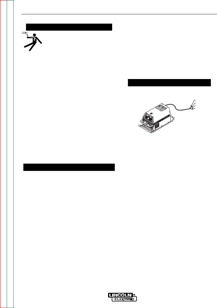
POWER CORD CONNECTION
A 10 ft. power cord is provided and wired into the machine. Follow the power cord connection instructions.
 CAUTION
•Incorrect connection may result in equipment damage.
-----------------------------------------------------------------------
BLACK
GREEN RED
WHITE OR BROWN
A
Single Phase Input
Connect green lead to ground per National Electrical Code.
Connect black and white leads to power.
Wrap red lead with tape to provide 600V insulation.
Three Phase Input
Connect green lead to ground per National Electric Code.
Connect black, red and white leads to power.
CONNECTIONS OF WIRE FEEDERS TO V350-PRO
LN-25 Connection Instructions
(Factory, Construction & Advanced Process versions can be connected.-Not recommended for Pulse Welding with the Advanced Process Model).
•Turn the Invertec power switch "off".
•Connect the electrode cable to the output terminal of polarity required by electrode. Connect the work lead to the other terminal.
•LN-25 with Remote Control options can be used with the Factory Advanced Process version of the V350. The 6-Pin (K444-1) and 14-pin (K444-2) remotes can be connected directly to the 6-pin & 14-pin MS-style connectors. The 42 Volt Remote Voltage and Output Control (K624-1) Kit can be connected to the V350’s 14-pin MS-style connector using Remote Control Cable assembly K627- [ ]. LN-25s with a K431-1 remote kit can be connected to the V350’s 14-pin MS-style connector using a K432 cable and K876 adapter. (See connection diagram S19899). Or the K432 cable could be modified with a K867 Universal Adapter Plug (See connection diagram S19405) to connect it to the
V350’s 14-pin MS-style connector.
V350-PRO
Return to Section TOC |
Return to Master TOC |
Return to Section TOC |
Return to Master TOC |
Return to Section TOC |
Return to Master TOC |
Return to Section TOC |
Return to Master TOC |
A-4 |
A-4 |
INSTALLATION
LN-7 Connection Instructions
An LN-7 can only be used with the “Factory” & “Advanced Process” versions of the 350-Pro.
•Turn the Invertec power switch "off".
•Connect the K480 control cable from the LN-7 to the 14-pin MS-style connector.
•Connect the electrode cable to the output terminal of the polarity required by electrode. Connect the work lead to the other terminal.
•Set the meter polarity switch on the front of the Invertec to coincide with wire feeder polarity used. The wire feeder will now display the welding voltage.
•If K480 is not available, see connection diagram S19404 for modification of K291 or K404 LN-7 input cable with K867 Universal Adapter Plug.
•If a remote control such as K857 is to be used with the LN-7, the remote can be connected directly to the 6-pin MS-style connector on the front of the Invertec or use a K864 adapter to connect the LN-7 and the remote to the 14-pin MS-style connector. (See connection diagram S19901)
LN-10 Connection Instructions
An LN-10 can only be used with the “Factory” & “Advanced Process” versions of the 350-Pro.
•Turn the Invertec power switch "off"
•Connect the K1505 control cable from the LN-10 to the 14-pin MS-style connector.
•Connect the electrode cable to the output terminal of polarity required by the electrode. Connect the work lead to the other terminal.
•Set the meter polarity switch on the front of the Invertec to coincide with wire feeder polarity used.
•See the LN-10 manual for details on accessing Control DIP Switch
LN-742 Connection Instructions
An LN-742 can only be used with the “Factory” & “Advanced Process” versions of the 350-Pro.
•Turn the Invertec power switch "off"
•Either a K591 or a K593 Input cable assembly is required to connect the LN-742 to the Invertec.
•Connect the control cable from the LN-742 to the 14-pin MS-style connector.
•Connect the electrode cable to the output terminal of the polarity required by electrode. Connect the work lead to the other terminal.
•Set the meter polarity switch on the front of the Invertec to coincide with wire feeder polarity used. The wire feeder will now display the welding voltage.
•If a remote control such as K857 is to be used with the LN-742, the remote can be connected directly to the 6-pin MS-style connector on the front of the Invertec or use a K864 adapter to connect the LN-742 and the remote to the 14-pin MS-style connector.
Cobramatic Connection Instructions
A Cobramatic can only be used with the “Factory” & “Advanced Process” versions of the 350-Pro.
•Turn the Invertec power switch "off"
•Connect the control cable from the Cobramatic to the 14-pin MS-style connector.
•Connect the electrode cable to the output terminal of the polarity required by electrode. Connect the work lead to the other terminal.
•Set the meter polarity switch on the front of the Invertec to coincide with wire feeder polarity used.
•If a remote control such as K857 is to be used with the Cobramatic, the remote can be connected directly to the 6-pin MS-style connector on the front of the Invertec or use a K864 adapter to connect the cobramatic and the remote to the 14-pin MSstyle connector.
TIG Module K930-2
The TIG Module connects to the Factory and Advanced Process V350-Pro versions with a K936-1 (9-14 pin) control cable. Connect the K936-1 to the MS-style connector.
The TIG Module can also be used with the V350-Pro Construction version. A K936-4 control cable is required to supply 115VAC to the TIG Module from an external 115VAC supply.
General Instructions for Connection of Wire Feeders to V350-Pro
Wire feeders other than those listed above may be used provided that the auxiliary power supply rating of the V350-Pro is not exceeded. K867 universal adapter plug is required. See connection diagram S24985 on page F-4.
REMOTE CONTROL OF INVERTEC
Remote Control K857, Hand Amptrol K963 and Foot
Amptrol K870.
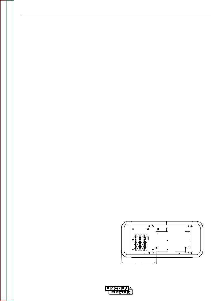
UNDERCARRIAGE MOUNTINGS
MOUNTING HOLE LOCATIONS
NOTE: MOUNTING SCREWS CAN NOT PROTRUDE MORE THAN 0.5 INCHES INSIDE THE MACHINE.
3.50
 1/4-20 NUT (4 PLACES) 5.50
10.00
11.84 |
4/01 |
M19527
V350-PRO
Return to Section TOC |
Return to Master TOC |
Return to Section TOC |
Return to Master TOC |
Return to Section TOC |
Return to Master TOC |
Return to Section TOC |
Return to Master TOC |
A-5 |
A-5 |
INSTALLATION
PARALLEL OPERATION
The V350-Pro can be paralleled in CC mode. For best results, the currents of each machine should be reasonably well shared. As an example, with two machines set up in parallel for a 400 amp procedure, each machine should be set to deliver approximately 200 amps, not 300 amps from one and 100 amps from the other. This will minimize nuisance shutdown conditions. In general, more than two machines in parallel will not be effective due to the voltage requirements of procedures in that power range.
To set machine outputs, start with output control pots and arc control pots in identical positions. Use the output control pots to balance the currents and maintain the desired current. The arc control pots should be kept identical on the two machines.
V350-PRO

Return to Section TOC |
Return to Section TOC |
Return to Section TOC |
Return to Section TOC |
|
|
|
|
Return to Master TOC |
Return to Master TOC |
Return to Master TOC |
Return to Master TOC |
|
|
|
|
|
|
|
6-A |
|
|
|
PRO-V350 |
NOTES |
|
|
|
||
|
|
|
6-A

Return to Master TOC
Return to Master TOC
Return to Master TOC
Return to Master TOC
Section B-1 Section B-1
TABLE OF CONTENTS - OPERATION SECTION -
Operation............................................................................................................................... |
Section B |
Safety Precautions...................................................................................................................... |
B-2 |
General Description.............................................................................................................. |
B-2 |
Duty Cycle ............................................................................................................................ |
B-2 |
Operational Features and Controls ............................................................................................ |
B-2 |
Weld Mode Select....................................................................................................................... |
B-3 |
CC-Stick Soft.................................................................................................................. |
B-3 |
CC-Stick Crisp................................................................................................................ |
B-3 |
TIG GTAW ....................................................................................................................... |
B-4 |
CV-Wire........................................................................................................................... |
B-4 |
CV-Innersheild................................................................................................................. |
B-4 |
Advanced Process Panel............................................................................................................ |
B-5 |
Controls ...................................................................................................................................... |
B-6 |
Electrode Material....................................................................................................................... |
B-6 |
Hot Start & Arc Control............................................................................................................... |
B-6 |
Weld Mode Details...................................................................................................................... |
B-7 |
Pulse Programs .......................................................................................................................... |
B-8 |
Lower Case Front ....................................................................................................................... |
B-9 |
CV Modes............................................................................................................................. |
B-9 |
TIG Mode ............................................................................................................................. |
B-9 |
CC-Stick Modes................................................................................................................... |
B-9 |
Types of Remote Output Control................................................................................................ |
B-9 |
Types of Remote Weld Terminal Control .................................................................................... |
B-9 |
Auxiliary Power ......................................................................................................................... |
B-10 |
Limitations................................................................................................................................. |
B-10 |
Recommended Processes........................................................................................................ |
B-10 |
Descriptions of Special Welding Processes Available on this Machine................................... |
B-11 |
V350-PRO

Return to Section TOC |
Return to Master TOC |
Return to Section TOC |
Return to Master TOC |
Return to Section TOC |
Return to Master TOC |
Return to Section TOC |
Return to Master TOC |
B-2 |
OPERATION |
B-2 |
||||||||||
|
|
|
|
|
|
|
|
|
||||
SAFETY PRECAUTIONS |
|
|
DUTY CYCLE |
|
|
|||||||
|
|
|
|
|
|
|
|
|
|
|
||
|
|
|
|
|
|
|
|
|
|
|||
|
|
|
|
|
|
WARNING |
|
|
The V350-Pro is rated at 350 amps, 60% duty cycle |
|||
|
|
|
|
|
|
|
|
|
(based on a 10 minute cycle). It is also rated at 300 |
|||
|
|
|
|
|
|
ELECTRIC SHOCK can kill. |
||||||
|
|
|
|
|
|
amps, 100% duty cycle. |
|
|
||||
|
|
|
|
|
|
• Do not touch electrically live parts or |
|
|
||||
|
|
|
|
|
|
|
|
|
||||
|
|
|
|
|
|
electrode with skin or wet clothing. |
OPERATIONAL FEATURES and CONTROLS: |
|||||
|
|
|
|
|
|
• Insulate yourself from work and |
||||||
|
|
|
|
|
|
ground. |
|
|
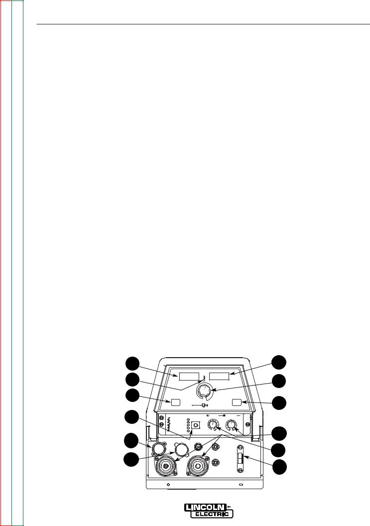
UPPER CONTROL PANEL |
|
|
|
|
|
|
|
|
|
• Always wear dry insulating gloves. |
|
|
||||
------------------------------------------------------------------------ |
1. AMPS Meter |
|
|
|||||||||
|
|
|
|
|
|
FUMES AND GASES can be dangerous. |
• Prior to STICK or TIG operation (current flow), the |
|||||
|
|
|
|
|
|
• Keep your head out of fumes. |
meter displays preset current value (+/- 2 amps or |
|||||
|
|
|
|
|
|
• Use ventilation or exhaust to remove |
+/- 3%, whichever is greater). |
|
|
|||
|
|
|
|
|
|
fumes from breathing zone. |
• Prior to CV operation, the meter displays four dash- |
|||||
|
|
|
|
|
|
|
|
|
es indicating non-presettable AMPS. |
|
|
|
|
|
|
|
|
|
|
|
|
|
|
||
------------------------------------------------------------------------ |
• During welding, this meter displays actual average |
|||||||||||
|
|
|
|
|
|
WELDING SPARKS can |
cause fire or |
amps. |
|
|
||
|
|
|
|
|
|
explosion. |
|
|
• After welding, the meter holds the actual current |
|||
|
|
|
|
|
|
• Keep flammable material away. |
value for 5 seconds. Output adjustment while in the |
|||||
|
|
|
|
|
|
• Do not weld on closed containers. |
"hold" period results in the "prior to operation" char- |
|||||
|
|
|
|
|
|
|
|
|
acteristics stated above. The displays blink indicat- |
|||
------------------------------------------------------------------------ |
ing that the machine is in the "Hold" period. |
|
|
|||||||||
|
|
|
|
|
|
ARC RAYS can burn eyes and skin. |
2. VOLT METER |
|
|
|||
|
|
|
|
|
|
• Wear eye, ear and body |
|
|
||||
|
|
|
|
|
|
protection. |
|
|
• Prior to CV operation (current flow), the meter dis- |
|||
|
|
|
|
|
|
|
|
|
plays desired preset voltage value (+/- .5V). |
|
|
|
------------------------------------------------------------ |
• Prior to STICK or TIG operation, the meter displays |
|||||||||||
the Open Circuit Voltage of the Power Source or four |
||||||||||||
|
|
|
|
|
|
|
|
|
||||
See additional warning information at |
dashes if the output has not been turned on. |
|
|
|||||||||
• During welding, this meter displays actual average |
||||||||||||
|
front of this operators manual. |
volts. |
|
|
||||||||
----------------------------------------------------------- |
• After welding, the meter holds the actual voltage |
|||||||||||
GENERAL DESCRIPTION |
value for 5 seconds. The displays blink indicating |
|||||||||||
that the machine is in the "Hold" period. |
|
|
||||||||||
|
|
|
|
|
|
|
|
|
• Output adjustment while in the "hold" period results |
|||
The Invertec V350-Pro offers multi-process CV, CC, |
in the "prior to operation" characteristics |
stated |
||||||||||
above. |
|
|
||||||||||
and DC welding and is rated 350 amps, 34 volts at a |
|
|
||||||||||
|
|
|
||||||||||
60% duty cycle. The V350-Pro is available in either a |
3. OUTPUT CONTROL |
|
|
|||||||||
Construction version (no wire feeder connection and |
|
|
||||||||||
• Output control is conducted via a single turn poten- |
||||||||||||
auxiliary power) and a Factory & Advanced Process |
||||||||||||
tiometer. |
|
|
||||||||||
versions (includes wire feeder connection and related |
|
|
||||||||||
• Adjustment is indicated by the meters as |
stated |
|||||||||||
power) |
|
|
||||||||||
|
|
above. |
|
|
||||||||
. |
|
|
|
|
|
|
|
|
|
|
||
• The factory model is the construction model with |
• When in TIG modes, this control sets the maximum |
|||||||||||
|
the addition of the Wire Feeder/Remote Adapter. |
welding current. Full depression of a foot or hand |
||||||||||
|
|
|
|
|
|
|
|
|
Amptrol results in the preset level of current. |
|
|
|
• In this form, the V350-Pro provides the hardware to |
4. WELD TERMINALS-REMOTE / ON |
|
|
|||||||||
|
|
power and connect to 24, 42 or 115 VAC wire feeders. |
|
|
||||||||
|
|
• Two status lights indicate the location of trigger con- |
||||||||||
|
|
|
|
|
|
|
|
|
||||
• The advanced process model is the factory model |
trol as determined by the "WELD TERMINALS" push |
|||||||||||
button. |
|
|
||||||||||
|
with an advanced process panel installed in place of |
|
|
|||||||||
|
• If trigger control is local "weld terminals on", the ON |
|||||||||||
|
the standard mode panel. In this form, the V350-Pro |
|||||||||||
|
display will be lit. |
|
|
|||||||||
|
provides access to the 5 standard weld modes (Stick |
|
|
|||||||||
|
• If trigger control is remote "weld terminals remotely |
|||||||||||
|
Soft, Stick Crisp, TIG, CV-Wire, |
CV-Innershield), |
||||||||||
|
controlled", the REMOTE display will be lit. |
|
|
|||||||||
|
gouge, constant power and pulse MIG weld modes. |
|
|
|||||||||
|
|
|
|
|||||||||
V350-PRO
Return to Section TOC |
Return to Master TOC |
Return to Section TOC |
Return to Master TOC |
Return to Section TOC |
Return to Master TOC |
Return to Section TOC |
Return to Master TOC |
B-3 |
B-3 |
OPERATION
•The unit will power up in "pre-determined preferred" trigger modes.
STICK = ON
CV = REMOTE
TIG = REMOTE if remote output controls are attached to the machine.
TIG = 0N if remote output controls are not attached to the machine.
For all versions, these trigger modes can be over-ridden (switched) with the WELD TERMINALS push button. When changed, the unit will power up in the configuration it was in when it was last powered down.
5. THERMAL
•This status light indicates when the power source has been driven into thermal overload. If the output terminals were "ON", the "ON" light will blink indicating that the output will be turned back on once the unit cools down to an acceptable temperature level. If the unit was operating in the "REMOTE" mode, the trigger will need to be opened before or after the thermal has cleared and closed after the machine has cooled down to an acceptable temperature to establish output.
6. CONTROL-REMOTE / LOCAL
•Two status lights indicate the location of output control as pre-determined by the power sources auto-configure system.
•The LOCAL display will be lit when control is at the power source.
•The REMOTE display will be lit when a remote pot/control is detected.
These Output Control configurations can be overridden (switched) with the CONTROL push button. When changed, the unit will power up in the configuration it was in when it was last powered down.
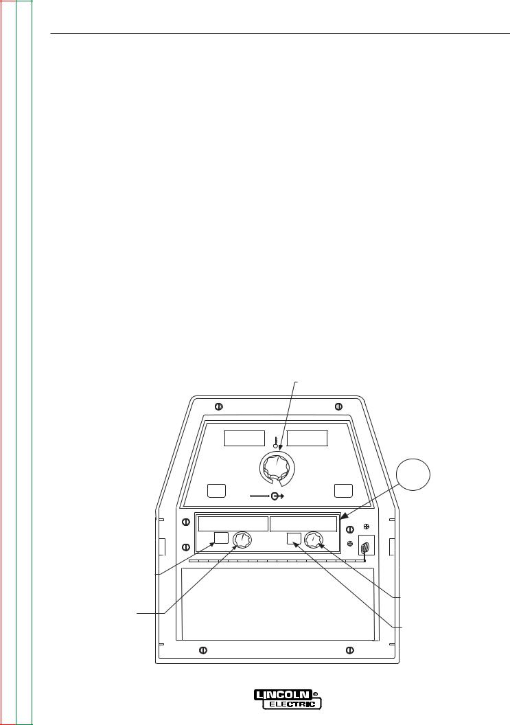
7.WELD MODE SELECT - FACTORY AND CONSTRUCTION (See Figure B.1)
The Mode Control button selects from the following welding modes.
CC-STICK SOFT: The Stick Soft process features continuous control ranging from 5 to 425 amps. This mode was intended for most SMAW applications, and Arc Gouging.
•Arc Gouging: Setting the output of the Stick Soft mode to 425 amps will enable the arc-gouging mode. The actual output current will depend on the size of carbon used. The recommended maximum size carbon is 5/16".
•The Hot Start control regulates the starting current at arc initiation. Hot Start can be adjusted from minimum (0), with no additional current added at arc start, to maximum (10), with double the preset current or 425 amps (max of machine) added for the first second after arc initiation.
•The Arc Control regulates the Arc Force to adjust the short circuit current. The minimum setting (-10) will produce a "soft" arc and will produce minimal spatter. The maximum setting (+10) will produce a "crisp" arc and will minimize electrode sticking.
CC-STICK CRISP:The Stick Crisp mode features continuous control from 5 to 425 amps. This mode was intended primarily for pipe welding applications.
•The Hot Start control regulates the starting current at arc initiation. Hot Start can adjust starting current up or down by 25% of the preset value. The recommended setting for Hot Start is 5 where the initial current is equal to the preset current.
Hidden Middle Control Panel – Mode Panel
|
|
FIGURE B.1. |
|
|
||||
1 |
|
|
|
|
|
|
|
2 |
5 |
|
AMPS |
|
|
VOLTS |
|
3 |
|
6 |
CONTROL |
|
|
|
WELD TERMINALS |
|
||
|
|
REMOTE |
|
|
|
REMOTE |
|
4 |
|
|
LOCAL |
|
OUTPUT |
ON |
|
||
|
SELECT |
|
|
|
SELECT |
|||
|
|
|
|
|
|
|
||
7 |
|
|
|
HOT START |
ARC CONTROL |
|
||
CC-STICK SOFT |
7018 |
|
5 |
6 |
|
0 |
|
|
|
4 |
-2 |
|
|||||
|
|
|
|
|
+2 |
|
||
|
CC-STICK CRISP 6010 |
3 |
|
7 |
-4 |
+4 |
|
|
|
TIG GTAW |
|
2 |
|
8 |
-6 |
+6 |
|
|
CV-WIRE |
|
1 |
|
9 |
-8 |
+8 |
|
|
|
|
|
8 |
||||
|
CV-FLUX CORED |
|
SELECT |
0 |
10 |
-10 |
+10 |
|
|
|
|
|
|
|
SOFT |
CRISP |
|
11 |
|
|
|
|
|
|
|
|
12 |
|
|
|
|
|
|
|
9 |
|
|
|
|
|
|
|
10 |
|
|
|
|
|
|
|
|
|
|
V350-PRO

Return to Section TOC |
Return to Master TOC |
Return to Section TOC |
Return to Master TOC |
Return to Section TOC |
Return to Master TOC |
Return to Section TOC |
Return to Master TOC |
B-4 |
OPERATION |
B-4 |
|
|
|
|
|
•The Arc Control regulates the Arc Force to adjust the short circuit current. The minimum setting (-10) will produce a "soft" arc and will produce minimal spatter. The maximum setting (+10) will produce a "crisp" arc and will minimize electrode sticking.
TIG GTAW: The TIG mode features continuous control from 5 to 425 amps. The TIG mode can be run in either the TIG touch start or high frequency (optional equipment required) assisted start mode.
•The Hot Start control selects the starting mode desired. A setting of less than 5, the TIG lift start mode is selected. The OCV is controlled below 10v and the short circuit "TIG touch" current is maintained at 25 amps independent of the preset current. When the tungsten is lifted, an arc is initiated and the output is regulated at the preset value. Hot start settings between 0 and 5 regulate the arc initiation current. A setting of 5 results in the most positive arc initiation. A setting of 0 reduces hot start.
•Hot Start settings between 5 and 10, select high frequency assisted starting TIG mode. In this range, the OCV of the machine is controlled between 50 and 70 volts. If using the Lincoln K930-1 TIG Module, set the Hot start to 10 for maximum OCV.
•The Arc Control is not used in the TIG mode.
TIG SOLENOID OPTION
The Solenoid only operates when the V350 is in the TIG mode. If the Weld Terminals are in “Remote” then the solenoid will open when the arc start switch is closed. The solenoid will close after the arc switch has been opened and the post flow time expired.
If the Weld Terminals are turned “ON”, then the solenoid will open when the electrode is touched to the work. The electrode needs to remain in contact with the work to allow for gas coverage before attempting to start the arc. The solenoid will close after the arc has been broken and the post flow time expired.
CV-WIRE: The CV-WIRE mode features continuous control from 10 to 40 volts. The mode was intended for most GMAW, FCAW, and MCAW applications.
•The Hot Start control is not used in the CV-WIRE mode.
•The Arc Control regulates pinch effect. At the minimum setting (-10), minimizes pinch and results in a soft arc. Low pinch settings are preferable for welding with gas mixes containing mostly inert gases. At the maximum setting (+10), maximizes pinch effect and results in a crisp arc. High pinch settings are preferable for welding FCAW and GMAW with CO2.
CV-INNERSHEILD: The CV-INNERSHEILD mode features continuous control from 10 to 45 volts. This mode was designed for self-shielded flux cored wires that require tight voltage control.
•The Hot Start control is not active in the CV-FLUX CORED mode.
•The Arc Control regulates pinch effect. At the minimum setting (-10), minimizes pinch and results in a soft arc. At the maximum setting (+10), maximizes pinch effect and results in a crisp arc. Most selfshielded wires work well at an Arc Control setting of 5.
V350-PRO
Return to Section TOC |
Return to Master TOC |
Return to Section TOC |
Return to Master TOC |
Return to Section TOC |
Return to Master TOC |
Return to Section TOC |
Return to Master TOC |
B-5 |
B-5 |
OPERATION
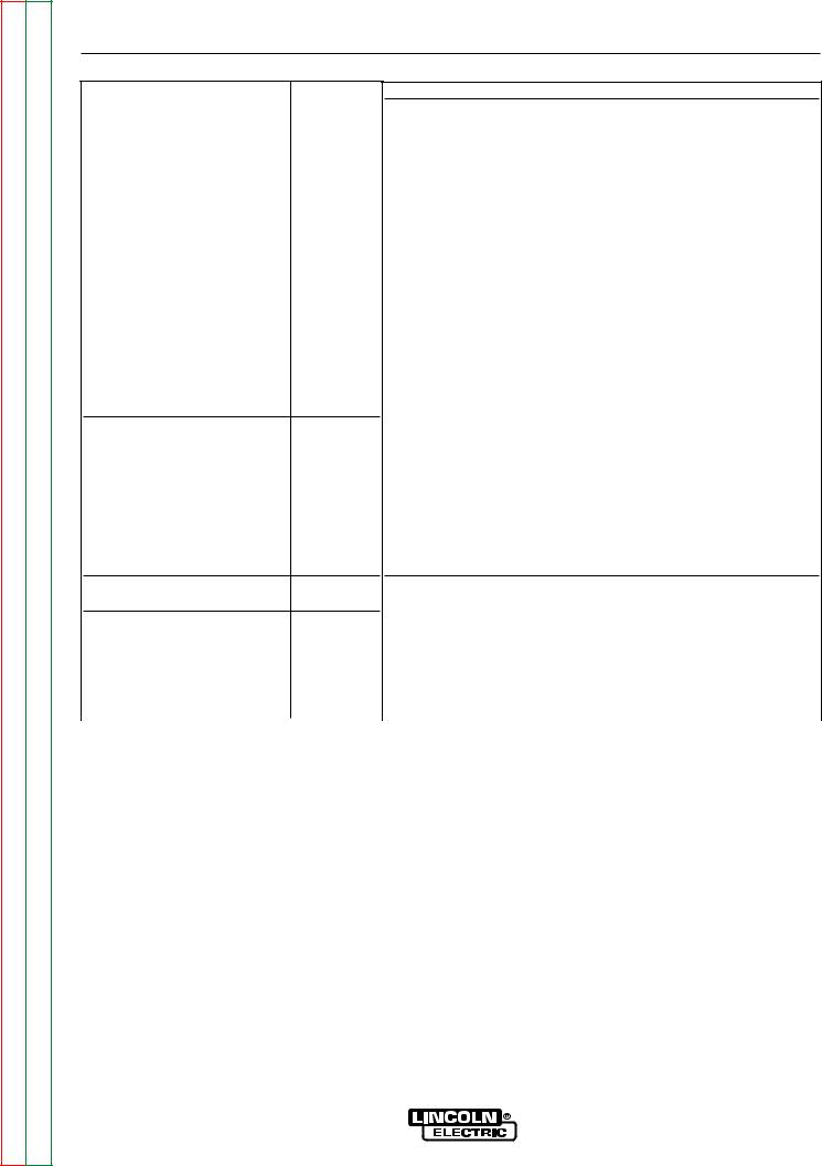
7A. ADVANCED PROCESS PANEL
(See Figure B.2)
To program Welding modes. SELECT knob is used to Scroll through all Welding modes. The MEMORY button is used to store and access Welding modes into locations M1 thru M8.
Modes:
In addition to the 5 welding modes described in SECTION 7, the Advanced Process Panel allows you to select the Following additional modes.
• Power Mode
In the Power Mode;
The work point will be in the Volts window. The Amp window will have CP displayed indicating Constant Power. Once current starts flowing and during the 5 second “Hold” feature the displays will show Volts and Amps respectively. Refer to the detailed explanation at the end of this section.
• Gouge
Air Carbon Arc Cutting (CAC-A) is a physical means of removing base metal or weld metal by using a carbon electrode, an electric arc and compressed air.
• Pulsed Modes
In Pulse Modes;
The work point will be in the Amps window and should be set close to the wire feed speed of the wire feeder in inches per minute. The Volts window will have SPd displayed indicating Wire Feed Speed. Once current starts flowing and during the 5 second “Hold” feature the displays will show amps and volts.
Pulse Mode features that are displayed while selecting a Welding pulse mode are listed below;
Steel - .030, .035, .045, .052 – Argon Blends Stainless Steel - .030, .035, .045 – Argon Blends & Helium/Argon Blends
Aluminum - .035, 3/64, 1/16 – 4043 & 5356 Metal Core - .045, .052 – Argon Blends Nickel - .035, .045 – Argon/Helium blends
Refer to the detailed explanation at the end of this section.
ADVANCED PROCESS PANEL VERSION
FIGURE B.2
OUTPUT KNOB
AMPS |
VOLTS |
|
CONTROL |
|
WELD TERMINALS |
REMOTE |
|
REMOTE |
LOCAL |
OUTPUT |
ON |
|
|
|
SELECT |
|
SELECT |
MEMORY |
SELECT |
SELECT |
ADJUST |
MEMORY BUTTON (M1 THRU M8)
SELECT KNOB (SCOLLS WELDING PROCESSES)
7A
ADJUST KNOB
(0 THRU 10-HOT START) (-10 THRU 0 AND
0 THRU +10-ARC CONTROL)
SELECT BUTTON
(HOT START OR ARC CONTROL)
V350-PRO

Return to Section TOC |
Return to Master TOC |
Return to Section TOC |
Return to Master TOC |
Return to Section TOC |
Return to Master TOC |
Return to Section TOC |
Return to Master TOC |
B-6 |
B-6 |
OPERATION
CONTROLS: (See Figure B.2.)
The MEMORY button and SELECT knob are used together to select a welding process and store it in memory (M1 thru M8). The SELECT knob scrolls through the, welding process modes and memory M1 thru M8. The MEMORY button stores the welding process in memory.
•SELECT button" (The right button) selects between the "Hot Start" or "Arc Control". The < will indicate the active feature shown below.
Right Digital Window "Hot Start" (-10 to 0 +10) "Arc Control" (0 to 10) <
•The ADJUST knob adjusts the desired settings for the Hot Start or Arc Control feature that is active.
WELDING PROCESS MODES AVAILABLE
Stick SMAW, TIG GTAW
Gouge CAG, CV MIG GMAW
CV Flux Core, Pulse MIG
ELECTRODE MATERIAL
Steel, Metal Core, Stainless, Aluminum, Nickel
EXAMPLE OF SAVING WELDING MODES TO MEMORY
The following example is how to select Pulse MIG using .035 steel and store it into memory.
1.Turn the Select knob until welding process is displayed.
LEFT WINDOW |
RIGHT WINDOW |
Pulse MIG |
Argon Blends |
Steel .035 |
|
2.Wait two seconds and the right window will display Arc Control on the second line on the right side.
Pulse MIG |
Argon Blends |
Steel .035 |
Arc Cntrl ### < |
3.SPd is displayed in the upper right Volts window. The left Amps window matches the desired wire feed speed that is set on the wire feeder. Adjust the Output knob until desired number is displayed.
4.Start welding. If the arc length is too short turn the Output knob up. If the arc length is too long turn the
Output knob down.
The Arc Control which is displayed in the right digital window can be used to fine-tune the arc length and characteristics.
5.After all adjustments have been made press and hold the Memory button until the display changes. The right and the left window will display what memory to save in, lets say M1. To store in M1 push the Memory button again to save the Pulse Mig mode to memory M1.
6.The display in the digital windows will read as follows:
M1 Pulse MIG |
Argon Blends |
Steel .035 |
Arc Cntrl 1.2 |
7.Saving or entering a second welding mode to a memory, M2. Turn the Select knob until the desired welding process mode is displayed in right digital window. Then follow steps 1 thru 6.
Press the Memory button till the digital window reads,
Save to MEM M2
Press the Memory button again and the New Welding process is saved in M2.
8.Adjust the output control to the correct wire feed setting and the V350-PRO is ready to weld again. (Note: The wire feed speed setting is not stored in memory and will need to be reset.)
9.Adjust the Arc Control and note that the M1 goes away indicating that the V350-PRO settings no longer match what is stored in memory. Going back to the original settings will not bring the M1 back. You will need to push the Memory button to recall the original settings in M1.
Note: After all memory’s M1 thru M8 are used and the welder needs to store another welding process, a new welding process will overwrite what was originally in the memory and will read,
Save to MEM M1 Overwrite
M1 which stored Pulse Mig is Overwritten with the new welding process.
LN-10/DH-10 Wire Feeder Compatibility Note:
The LN-10 and DH-10 feeders can be used to pulse weld and in the power mode with the panel. The displays on the LN-10 & DH-10 do not show the wire feed speed or power.
8. HOT START and ARC CONTROL features have different functions depending on the welding Mode that is active. Each feature is described under the welding mode heading. (See Item 7 or 7.A for specified Mode Operations) (See Figure B.1 or B.2)
V350-PRO

Return to Section TOC |
Return to Master TOC |
Return to Section TOC |
Return to Master TOC |
Return to Section TOC |
Return to Master TOC |
Return to Section TOC |
Return to Master TOC |
B-7 |
|
B-7 |
|
|
OPERATION |
WELD MODE DETAILS: |
|
|
|
|
|
Mode |
Range |
Comments |
|
|
|
Stick Soft |
5 - 425 amps |
The stick soft mode is the best selection for general stick |
|
|
applications. |
|
|
Arc Control = Arc Force |
|
|
Hot Start = Initial hot start current (min = start a match set amps, Max. |
|
|
= greatest hot start current) During hot start, arc force is set |
|
|
at high and is fast response. |
|
|
For gouging applications: Turn current up to 425 amps. |
|
|
|
Stick Crisp |
5 - 425 amps |
The stick crisp mode features an aggressive arc force routine well suit- |
|
|
ed for Exx10, Exx11 series electrodes. |
|
|
Arc Control = Arc Force |
|
|
Hot Start = Initial hot start current (Mid range = welding current and will |
|
|
vary up and down with knobcontrol.) During hot start, arc |
|
|
force is set at high and is fast response. |
|
|
For gouging applications: Turn current up to 425 amps. |
|
|
|
GTAW (Tig mode) |
5 - 425 amps |
The tig mode produces a soft, steady constant current waveform for |
|
|
either touch start or high frequency assisted start DC GTAW applica- |
|
|
tions. |
|
|
Hot Start = Min to Mid range = Touch start with low OCV |
|
|
Mid to Max range = High frequency assistedstarting with adjustable |
|
|
OCV up to 70 volts. |
|
|
|
GMAW - CV |
10 - 45 volts |
The GMAW - CV mode is the best selection for general MIG welding, |
|
|
Metal core, and gas shielded applications. |
|
|
Arc Control = Pinch (Min = min pinch, softest arc), |
|
|
(Max = max pinch, crispest arc) |
|
|
|
FCAW-SS |
10 - 45 volts |
The FCAW-SS mode is designed for Self Shielded Innershield products |
|
|
that require tight voltage control. For example; the NR 203 series or NR |
|
|
207) |
|
|
Arc Control = Pinch (Min = min pinch, softest arc), |
|
|
(Max = max pinch, crispest arc, ) |
|
|
|
|
ADVANCED PULSE PANEL WELDING PROGRAMS |
|
|
|
|
Gouging |
60 - 425 amps |
The gouging mode is a low power version of other Lincoln welding |
|
|
equipment gouging programs, for example a PowerWave 455. |
|
|
|
GMAW - Power |
1 - 18 (No Units) |
Refer to the detailed explanation at the end of this section. |
|
|
This mode does not allow preset voltage. In the short arc GMAW |
|
|
mode, the set KW will not equal the actual Volts * Amps. The set |
|
|
power is regulated only when an arc is present. During shorting, the |
|
|
output is allowed to increase to clear the short. |
|
|
|
V350-PRO
Return to Section TOC |
Return to Master TOC |
Return to Section TOC |
Return to Master TOC |
Return to Section TOC |
Return to Master TOC |
Return to Section TOC |
Return to Master TOC |
B-8 |
B-8 |
OPERATION
PULSE PROGRAMS:
|
MODE |
Range (IPM*) |
|
.030 |
Steel |
65 |
- 1200 |
.035 |
Steel |
55 |
- 800 |
.045 |
Steel |
50 |
- 700 |
.052 |
Steel |
75 |
- 550 |
.045 |
Metal Core |
50 |
- 650 |
.052 |
Metal Core |
50 |
- 500 |
.030 |
Stainless Ar Blends |
85 |
- 770 |
.030 |
Stainless He Ar CO2 |
110 - 770 |
|
.035 |
Stainless Ar Blends |
65 |
- 770 |
.035 |
Stainless He Ar CO2 |
75 |
- 770 |
.045 |
Stainless Ar Blends |
50 |
- 600 |
.045 |
Stainless He Ar CO2 |
50 |
- 600 |
.035 Aluminum 4043 |
100 - 700 |
||
.035 Aluminum 5356 |
115 - 740 |
||
3/64 Aluminum 4043 |
80 |
- 550 |
|
3/64 Aluminum 5356 |
85 |
- 700 |
|
1/16 Aluminum 4043 |
75 |
- 325 |
|
1/16 Aluminum 5356 |
75 |
- 450 |
|
.035 Nickel Alloys (Non Adaptive) |
80 - 700 |
.045 Nickel Alloys (Non Adaptive) |
75 - 550 |
COMMENTS
The V350 pulse programs are non-synergic and allow independent control of the wire feed speed (at the wire feeder) and the arc length. The Output Control Knob on the V350, adjusts an "SPD" value. Similar to trim, the "SPD" value indicates the relative arc length setting. The "SPD" value displayed on the V350 may not match the actual wire feed speed! The value of "SPD" is meant to be a point at which to set the arc length relative to the wire feed speed and should be set the same as actual speed for a starting point. Depending on the application, the "SPD" value can be adjusted to obtain the desired arc length. Refer to the detailed explanation at the end of this section.
The operation of the Arc Control knob on the V350 is similar to the PowerWave series. As Arc Control is increased, the frequency is increased and the background reduced. Decreasing Arc Control will reduce frequency and increase background current. Arc Control acts to fine tune the arc plasma to the specific application.
Preferred gas selections:
Steel Argon Blends = Argon with CO2 additions from 2 to 20 % or Oxygen additions from 2 to 5%.
Stainless Argon Blends = Argon with Oxygen additions up to 2%.
Stainless He Ar CO2 = ~ 90% Helium, 7 1/2 % Argon 2 1/2 CO2 Aluminum 100% Argon
The Nickel Alloy pulse programs are non adaptive. The operator sets the output control knob to deliver the correct arc length at desired wire feed speed and stick out. While welding, the operator manipulates the stick out to maintain the correct arc length. This method of operation produces very stable arc performance considering the nature of nickel alloys.
Preferred gas: Argon/Helium Blends = for the best results add helium to the argon base from 0-25%.
|
|
|
|
|
|
PULSE ON PULSE |
||
|
|
|
|
|
|
|
|
|
.035 4043 |
(4x |
Pulse on Pulse) |
120 - 600 |
|
|
Arc Control = Pulse on Pulse frequency. For faster travel |
||
|
3/64 4043 |
(4x |
Pulse on Pulse) |
85 - 400 |
|
|
speed welds, the arc control should be increased. |
|
|
.035 5356 |
(5x |
Pulse on Pulse) |
130 - 700 |
|
|
For larger puddle, slower travel speeds, the arc control |
|
|
3/64 5356 |
(5x |
Pulse on Pulse) |
100 - 550 |
|
|
should be decreased. Refer to the detailed explanation at the |
|
|
|
|
|
|
|
|
|
end of this section. |
|
|
|
|
|
|
|||
*IPM (INCHES PER MINUTE) |
|
|
|
|
||||
|
|
|
|
|
|
|
|
|
V350-PRO
Return to Section TOC |
Return to Master TOC |
Return to Section TOC |
Return to Master TOC |
Return to Section TOC |
Return to Master TOC |
Return to Section TOC |
Return to Master TOC |
B-9 |
B-9 |
OPERATION
LOWER CASE PANEL
The output studs, line switch and remote connector are located on the lower case front.
9. Both terminals are "Twist-Mate" connectors.
The Negative terminal is configured to accept the pass through gas system.
10.The METER POLARITY switch is located above the output connectors. The switch provides a work connection for wire feeder voltmeters. Place the switch in the position of the electrode polarity indicated by the decal. The switch does not change the welding polarity.
11.6-pin MS-style connector for remote control.
12.14-pin MS-style connector for wire feeder connection and remote control.
REMOTE CONTROL of the OUTPUT CONTROL and
WELD TERMINALS
The Invertec V350-Pro has auto sensing of remote output controls. If after connecting or removing a remote, the Invertec V350-Pro did not configure the way you would like the local or remote control settings can be changed by pushing the OUTPUT CONTROL or WELD TERMINAL button. (A user cannot select between the 6 and 14 pin MS-style connectors.)
CV modes
•The remote will default to the 14-pin MS-style connector if a remote is connected. If no remote is connected to the 14-pin MS-style connector then the remote will default to the 6-pin MS-style connector if a remote is connected to it.
•In all of the CV modes, the WELD TERMINAL control will default to REMOTE.
TIG mode
•The remote will default to the 6-pin MS-style if a remote control is connected to the 6-pin MS-style and to the 14-pin MS-style connector. If a remote is not connected to the 6-pin MS-style connector then the remote will default to the 14-pin MS-style connector if a remote is connected.
•If a remote control is connected to any of the MSstyle connectors the WELD TERMINAL control will default to REMOTE. If there are not any remote control devices attached the WELD TERMINAL control will default to ON.
CC-Stick modes
•The remote will default to only the 6-pin MS-style connector if a remote is connected to it.
•The WELD TERMINAL control will default to ON with or without a remote connected.
Types of Remote OUTPUT CONTROL
•The Invertec V350-Pro’s Output Control can be controlled by either a potentiometer connected between 77 & 75 with the wiper connected to 76 or a 0V to 10V DC supply connected between 76 & 75. (76 needs to be positive)
•14-Pin Ms-style connector lead 75 is pin G, lead 76 is pin F and lead 77 is pin E.
•6-Pin Ms-style connector lead 75 is pin C, lead 76 is pin B and lead 77 is pin A.
Potentiometer Control
•The total resistance should be between 2000 ohms (2K) and 10,000 ohms (10K)
•The machine output will be at minimum when lead 76 (wiper) is at the end of the potentiometer that is connected to 75. The machine’s output will increase as the wiper of the potentiometer is moved to the end that is connected to 77. (Note: In TIG mode, moving the lead 76 (wiper) to lead 77 would produce the current that has been set by the Invertec V350-Pro’s front panel Output Control.)
•Remotes of this type offered by Lincoln Electric are the K857, K812 and K870.
Voltage Control
•The supply must be an isolated supply. (Not referenced to earth ground, any auxiliary power from the Invertec V350-Pro or the welding output) The supply should be capable of supplying at least 20mA.
•0 volts supplied to 76 will set the Invertec V350-Pro to minimum output for the mode that has been selected while 10 volts supplied to 76 will set the Invertec V350-Pro to the maximum output for the mode. (Note: In TIG mode, 10 volts supplied to lead 76 would produce the current that has been set by the Invertec V350-Pro’s front panel Output Control.)
Types of Remote WELD TERMINAL Control
•The Invertec V350-Pro’s Weld Terminals can be controlled from each of the MS-style connectors. The circuit has a nominal OCV of 15VDC and requires a dry contact closure (less than 100 ohms) to activate the output of the Invertec V350-Pro.
•14-Pin MS-style connector, the Weld Terminals are controlled from pin C (lead 2) and pin D (lead 4). Pin C is positive.
•6-Pin MS-style connector, the Weld Terminals are controlled from pin D (lead 2) and pin E (lead 4). In the 6-pin MS-style connector pin D is positive.
V350-PRO

Return to Section TOC |
Return to Master TOC |
Return to Section TOC |
Return to Master TOC |
Return to Section TOC |
Return to Master TOC |
Return to Section TOC |
Return to Master TOC |
B-10 |
B-10 |
OPERATION
AUXILIARY POWER
•115VAC, 42VAC and 24VAC power is available from the 14-pin MS-style connector. The Construction model of the Invertec V350-Pro does not have the 14-pin MS-style connector) These supplies are intended to supply power for auxiliary equipment like wire feeders and the TIG Module.
•115VAC supply is rated at 2 amps and is protected by a 3.5 amp breaker.
•42 VAC supply is rated at 5.5 amps and is protected by a 6 amp breaker.
•24 VAC supply is rated at 5.5 amps and is protected by a 6 amp breaker.
LIMITATIONS
•The V350-Pro is not recommended for processes other than those listed.
•The V350-Pro can only be used with the recommended equipment and options.
RECOMMENDED PROCESSES
Properly equipped, the Invertec V350-Pro supports GMAW-P, FCAW, SMAW, GTAW and CAC-A processes for a variety of materials, including mild steel, stainless steel, cored wires, and aluminum.
V350-PRO

Return to Section TOC |
Return to Master TOC |
Return to Section TOC |
Return to Master TOC |
Return to Section TOC |
Return to Master TOC |
Return to Section TOC |
Return to Master TOC |
B-11 |
B-11 |
OPERATION
SPECIAL WELDING PROCESSES AVAILABLE ON THIS MACHINE
POWER MODE™
The Power Mode™ process was developed by Lincoln to maintain a stable and smooth arc at low procedure settings which are needed to weld thin metal without pop-outs or burning-through. For Aluminum welding, it provides excellent control and the ability to maintain constant arc length. This results in improved welding performance in two primary types of applications.
•Short Arc MIG at low procedure settings.
•Aluminum MIG welding.
Power Mode™ is a method of high speed regulation of the output power whenever an arc is established. It provides a fast response to changes in the arc. The higher the Power Mode Setting, the longer the arc. If a welding procedure is not established, the best way to determine the Power Mode Setting is by experimentation until the desired output result is established.
In the Power Mode variables need to be set:
•Wire Feed Speed
•Output
•Arc Control
•For steel, use 75/25 Ar/CO2 shield gas.
•For Stainless, select a Helium blend Tri-Mix.
•For Aluminum, use 100% Ar.
Start by setting the wire feed speed based upon material thickness and appropriate travel speed. Then adjust the Output knob as follows:
•For steel, listen for the traditional “frying egg” sound of a good short-arc MIG procedure to know you have the process set correctly.
•For aluminum, simply adjust the Output knob until the desired arc length is obtained.
Note the Volts display is simply a relative number and DOES NOT correspond to voltage.
Some procedure recommendations appear in the table below.
Setting up a Power Mode procedure is similar to setting a CV MIG procedure. Select a shielding gas appropriate for a short arc process.
Recommended Welding Procedures for Power Mode
|
MATERIAL |
Aluminum 4043 |
Aluminum 5356 |
Mild Steel |
Mild Steel |
Mild Steel |
Mild Steel |
Mild Steel |
Mild Steel |
Stainless Steel |
Stainless Steel |
|||
|
|
|
|
|
|
|
|
|
|
|
|
|
||
|
WIRE |
|
E4043 |
E5356 |
L56 |
L56 |
L56 |
L56 |
L56 |
L56 |
E308L |
E308L |
||
|
|
|
|
|
|
|
|
|
|
|
|
|||
|
WIRE SIZE |
0.035 |
0.035 |
0.025 |
0.025 |
0.030 |
0.030 |
0.035 |
0.035 |
0.030 |
0.035 |
|||
|
|
|
|
|
|
|
|
|
|
|
|
|
||
|
GAS |
|
100% Ar. |
100% Ar. |
100% CO2 |
75/25% Ar/CO2 |
100% CO2 |
75/25% Ar/CO2 |
100% CO2 |
75/25% Ar/CO2 |
Tri-mix |
Tri-mix |
||
|
|
|
|
|
|
|
|
|
|
|
|
|
|
|
|
|
|
22 ga. |
125 |
/ 2.25 |
125 / 1.75 |
Not Recommended |
100 / 0.8 |
Not Recommended |
90 / 1.0 |
|
|
|
|
|
|
|
|
|
|
|
|
|
|
|
|
|
|
|
|
SETTINGMODEPOWER/WFS |
|
20 ga. |
150 |
/ 2.5 |
150 / 2.3 |
120 / 1.0 |
120 / 1.0 |
100 / 0.7 |
100 / 1.0 |
|
|
80 / 1.5 |
50 / 0.5 |
THICKNESSMATERIAL |
|
|
|
|
|
|
|
|
|
|
|
|
|
|
|
18 ga. |
200 |
/ 3.75 |
200 / 3.0 |
140 / 1.7 |
140 / 1.5 |
110 / 1.5 |
110 / 1.5 |
100 / 2.5 |
100 / 2.5 |
110 / 2.0 |
110 / 2.0 |
||
|
|
|
|
|
|
|
|
|
|
|
|
|
|
|
|
|
|
16 ga. |
300 |
/ 7.75 |
300 / 6.85 |
190 / 2.0 |
190 / 2.0 |
125 / 2.0 |
125 / 2.0 |
125 / 3.0 |
125 / 3.0 |
140 / 2.5 |
130 / 2.7 |
|
|
|
|
|
|
|
|
|
|
|
|
|
|
|
|
|
|
14 ga. |
400 |
/ 9.0 |
400 / 7.5 |
260 / 3.0 |
260 / 3.0 |
160 / 2.3 |
160 / 2.3 |
160 / 3.8 |
160 / 3.5 |
210 / 3.0 |
190 / 3.5 |
|
|
|
12 ga. |
|
/ 9.5 |
|
|
|
|
|
|
|
|
|
|
|
|
450 |
450 / 8.0 |
330 / 5.0 |
330 / 4.5 |
230 / 3.5 |
230 / 3.5 |
200 / 5.0 |
200 / 4.5 |
270 / 5.0 |
230 / 6.0 |
||
|
|
|
|
|
|
|
|
|
|
|
|
|
|
|
|
|
|
10 ga. |
500 |
/ 10.0 |
500 / 8.5 |
|
|
300 / 6.0 |
300 / 6.0 |
240 / 6.5 |
240 / 7.0 |
325 / 6.5 |
300 / 7.0 |
|
|
|
|
|
|
|
|
|
|
|
|
|
|
|
|
|
|
3/16 |
600 |
/ 11.25 |
600 / 9.5 |
|
|
400 / 7.5 |
400 / 7.0 |
|
|
|
|
|
|
|
|
|
|
|
|
|
|
|
|
|
|
|
|
|
|
1/4 |
|
|
700 / 11 |
|
|
|
|
|
|
|
|
|
|
|
|
|
|
|
|
|
|
|
|
|
|
|
V350-PRO
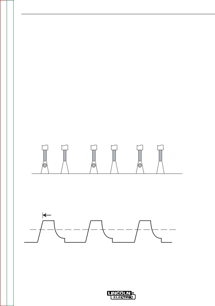
Return to Section TOC |
Return to Master TOC |
Return to Section TOC |
Return to Master TOC |
Return to Section TOC |
Return to Master TOC |
Return to Section TOC |
Return to Master TOC |
B-12 |
B-12 |
OPERATION
PULSE WELDING (GMAW-P)
The pulsed-arc process is, by definition, a spray transfer process wherein spray transfer occurs in pulses at regularly spaced intervals. In the time between pulses, the welding current is reduced and no metal transfer occurs.
Pulsed-arc transfer is obtained by operating a power source between low and high current levels. The high current level or “pulse” forces an electrode drop to the workpiece. The low current level or “background” maintains the arc between pulses. (See Figure below).
Pulsed MIG is an advanced form of welding that takes the best of all the other forms of transfer while minimizing or eliminating their disadvantages. Unlike short circuit, pulsed MIG does not create spatter or run the risk of cold lapping. The welding positions in pulsed MIG are not limited as they are with globular or spray and its wire use is definitely more efficient. Unlike the spray arc process, pulsing offers controlled heat input that allows better welding on thin materials, lower wire feed speeds and leads to less distortion and improved overall quality and appearance. This is especially important with stainless, nickel and other alloys that are sensitive to heat input.
In GMAW-P mode, arc control adjusts the background current and frequency of the wave. When arc control goes up, the frequency increases thus increasing the droplet transfer.
EACH PULSE DELIVERS ONE DROPLET OF WELD MATERIAL
PEAK AMPS
FREQUENCY

SPRAY TRANSITION
CURRENT
V350-PRO
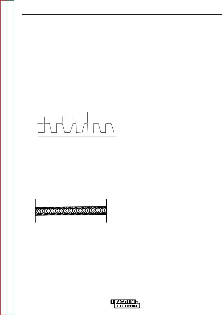
Return to Section TOC |
Return to Master TOC |
Return to Section TOC |
Return to Master TOC |
Return to Section TOC |
Return to Master TOC |
Return to Section TOC |
Return to Master TOC |
B-13 |
B-13 |
OPERATION
PULSE-ON-PULSE™ (GMAW-PP)
Pulse on Pulse™ is a Lincoln process specifically designed for use in welding relatively thin (less than 1/4" thick) aluminum (See the table below). It gives weld beads with very consistent uniform ripple.
In Pulse on Pulse modes, two distinct pulse types are used, instead of the single pulse type normally used in GMAW-P. A number of high energy pulses are used to obtain spray transfer and transfer metal across the arc. Such pulses are shown in the figure below. After a number "N" of such pulses, depending on the wire feed speed used, an identical number "N" of low energy pulses are performed. These low energy pulses, shown in the figure below, do not transfer any filler metal across the arc and help to cool the arc and keep the heat input low.
When Arc Control is used in the Pulse on Pulse modes, it does the same things it does in the other pulsed modes: decreasing the Arc Control decreases the droplet transfer and weld deposition rate. Increasing the Arc Control increases the droplet transfer and weld deposition rate. Since Arc Control varies weld droplet transfer rate, the Arc Control can be used to vary the ripple spacing in the weld bead.
BENEFITS OF PULSE ON PULSE FROM LINCOLN ELECTRIC
•Excellent appearance of the weld bead
•Improved cleaning action
•Reduced porosity
"N" PULSES |
"N" PULSES |
HIGH HEAT |
LOW HEAT |
PULSES |
PULSES |
PEAK |
|
AMPS |
|
BACKGROUND |
|
AMPS |
|
|
TIME |
The Peak Current, Background Current, and Frequency are identical for the high energy and low energy pulses. In addition to cooling the weld down, the major effect of the low energy pulses is that they form a weld ripple. Since they occur at very regular time intervals, the weld bead obtained is very uniform with a very consistent ripple pattern. In fact, the bead has its best appearance if no oscillation of the welding gun ("whipping") is used.(See the figure below)
Table B.2 shows WFS and Trim settings for common aluminum types and wire sizes when welding with Pulse-on-Pulse. The welds made to obtain the values in the table were fillet welds in the flat position. The values in the table can be helpful as a starting point to establish a welding procedure. From there, adjustments need to be made to set the proper procedure for each specific application (out-of-position, other types of joints, etc.).
The comments on the table below show values of WFS below which it is not recommended to weld. The reason is, that below these values the weld transfer will change from a spray arc to a short-arc, which is not advisable when welding aluminum.
WELDING PROCEDURES FOR PULSE-ON-PULSE
MATERIAL |
Aluminum 4043 |
Aluminum 4043 |
Aluminum 5356 |
Aluminum 5356 |
|||
|
|
|
|
|
|
|
|
GAS |
|
100% Ar. |
100% Ar. |
100% Ar. |
100% Ar. |
||
|
|
|
|
|
|
|
|
WIRE |
|
E4043 |
E4043 |
E5356 |
E5356 |
||
|
|
|
|
|
|
||
WIRE SIZE |
0.035 |
3/64 |
0.035 |
3/64 |
|||
|
|
|
|
|
|
|
|
|
|
|
|
|
|
|
|
MATERIAL THICKNESS /WFS CONTROLARC |
|
1/4 |
600 / 0 |
400 / 0 |
700 / 0 |
550 / 0 |
|
|
|
14 ga. |
250 / 0 |
200 / 0 |
230 / 0 |
225 / 0 |
|
|
|
|
|
|
|
|
|
|
|
10 ga. |
400 / 0 |
280 / 0 |
425 / 0 |
400 / 0 |
|
|
|
|
|
|
|
|
|
|
|
3/16 |
550 / 0 |
340 / 0 |
670 / 0 |
500 / 0 |
|
|
|
|
|
|
|
|
|
|
|
|
|
|
|
|
|
COMMENTS |
Not Recommended |
Not Recommended |
Not Recommended |
Not Recommended |
|||
below 200 WFS |
below 100 WFS |
below 200 WFS |
below 200 WFS |
||||
|
|
|
|||||
|
|
|
|
|
|
|
|
V350-PRO

Return to Section TOC |
Return to Section TOC |
Return to Section TOC |
Return to Section TOC |
|
|
|
|
Return to Master TOC |
Return to Master TOC |
Return to Master TOC |
Return to Master TOC |
|
|
|
|
|
|
|
14-B |
|
|
|
PRO-V350 |
NOTES |
|
|
|
||
|
|
|
14-B

Return to Master TOC
Return to Master TOC
Return to Master TOC
Return to Master TOC
C-1 C-1
TABLE OF CONTENTS
- ACCESSORIES SECTION -
Accessories........................................................................................................................... |
Section C |
Cobramatic & Tig Module Connection Instructions ................................................................... |
C-2 |
Options/Accessories................................................................................................................... |
C-2 |
Quick Disconnect Plugs ............................................................................................................. |
C-3 |
Connection of Lincoln Electric Wire Feeders............................................................ |
C-4 Thru C-11 |
V350-PRO/LN-25 with Optional 6 Pin K441-1 Remote....................................................... |
C-4 |
V350-PRO/LN-25 with Optional 6 Pin K857 Remote .......................................................... |
C-5 |
LN-25 with K431 Remote Option......................................................................................... |
C-6 |
V350-PRO/LN-25 with K867 Adapter .................................................................................. |
C-7 |
V350-PRO/LN-7 with K480 Control Cable .......................................................................... |
C-8 |
V350-PRO/LN-7 with K867 Adapter .................................................................................... |
C-9 |
V350-PRO/LN-742 ............................................................................................................. |
C-10 |
V350-PRO/LN-10 with K1505 Control Cable .................................................................... |
C-11 |
V350-PRO

Return to Section TOC |
Return to Master TOC |
Return to Section TOC |
Return to Master TOC |
Return to Section TOC |
Return to Master TOC |
Return to Section TOC |
Return to Master TOC |
C-2 |
C-2 |
ACCESSORIES
Cobramatic Connection Instructions
A Cobramatic can only be used with a Factory or "CE" version of the V350
1.Turn the Invertec power switch "off"
2.Connect the control cable from the Cobramatic to the 24/42 VAC 14-pin wire feeder amphenol on the rear of the Invertec.
3.Connect the electrode cable to the output terminal of the polarity required by electrode. Connect the work lead to the other terminal.
4.Set the meter polarity switch on the front of the Invertec to coincide with wire feeder polarity used.
5.If a remote control such as K857 is to be used with the Cobramatic, the remote can be connected directly to the 6pin amphenol on the front of the Invertec or use a K864 adapter to connect the cobramatic and the remote to the 24/42VAC 14pin wire feeder amphenol connector on the rear of the Invertec.
TIG Module K930-2
The TIG Module connects to the V350-Pro Factory or CE versions with a K936-1 (9-14 pin) control cable. Connect the K936-1 to the 115VAC Wire Feeder Amphenol on the rear of the V350-Pro.
The TIG Module can also be used with the V350 Construction version. A K936-4 control cable is required to supply 115VAC to the TIG Module from an external 115VAC supply.
General Instructions for Connection of Wire Feeders to V350-Pro
Wire feeders other than LN-7 and LN-25 may be used provided that the auxiliary power supply capacity of the V350-Pro is not exceeded. K867 universal adapter plug is required. See connection diagram S19406 and S19386 at the back of this manual for more information.
Remote Control of Invertec
Remote Control K857, Hand Amptrol K963 and Foot
Amptrol K870.
OPTIONS / ACCESSORIES
Construction Version – K1728-2
•All welding modes for this model run with local output control and weld terminals ON (e.g. Stick, TIG, LN25 off the arc).
K930-1 |
TIG Module |
K428,K446, K449 |
LN-25(Off the Arc) |
"CE" Version – K1728-3
•The "CE" version is the Factory version with the addition of power line filtering allowing the machine to comply with the European and Australian EMC emission requirements.
Field Installed Options/Accessories
Two versions of the V350-Pro are available from the factory for both the CE and ROW versions.
Options for K1728-1 Factory and K1728-3 "CE" V350’s
•TIG Gas Control Kit – K1762-2
•Advanced Process Panel – K1763-1
Options for all models of V350-PRO
•Undercarriage – K1764-1
•Valet Style Undercarriage - K1838-1
Welding Cable Connectors:
•K852-70 1/0-2/0 cable
•K852-95 2/0-3/0 cable
FACTORY VERSION and
ADVANCED PROCESS VERSION
K857 |
Remote Output Control |
K814 |
Arc Start Switch |
K812 |
Hand Operated Amptrol |
K870 |
Foot Operated Amptrol |
Note: All of the above remote controls connect directly to the 6-pin MS-style connector, with either a K864 or K876 adapter and connect it to the 14 pin wire feeder MS-style connector. (See Diagram in Section F-1)
K930-[ ] |
TIG Module |
|
K428, K446, K449 |
LN-25 * |
|
K617 |
(-1 or -2) K618 (-1 or -2) |
LN-742 |
K440 |
(-1), K567-1 |
LN-7 GMA |
K1559-1, K1564-1 |
LN-10 |
|
K1499-1, K1521-1 |
DH-10 |
|
K1587-1 |
Cobramatic |
|
*Not recommended for pulse welding
V350-PRO
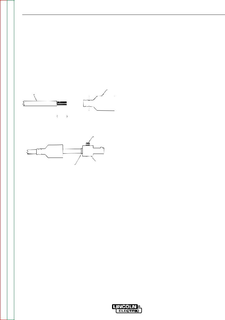
Return to Section TOC |
Return to Master TOC |
Return to Section TOC |
Return to Master TOC |
Return to Section TOC |
Return to Master TOC |
Return to Section TOC |
Return to Master TOC |
C-3 |
C-3 |
ACCESSORIES
QUICK DISCONNECT PLUGS
A quick disconnect system is used for the welding cable connections. The K852-70 is designed to accept a welding cable size of 1/0 to 2/0.
1.Remove 25mm (1 in.) of welding cable insulation.
2.Slide rubber boot onto cable end. The boot end may be trimmed to match the cable diameter. Soap or other lubricant will help to slide the boot over the cable.
BOOT
WELDING CABLE
 25 mm
25 mm 
 TRIM
TRIM
1 in.
3.Slide the copper tube into the brass plug.
4.Insert cable into copper tube.
SET SCREW
BRASS PLUG
COPPER TUBE
5.Tighten set screw to collapse copper tube. Screw must apply pressure against welding cable. The top of the set screw will be well below the surface of the brass plug after tightening.
6.Slide rubber boot over brass plug. The rubber boot must be positioned to completely cover all electrical surfaces after the plug is locked into the receptacle.
V350-PRO
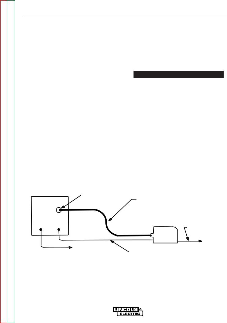
Return to Section TOC |
Return to Master TOC |
Return to Section TOC |
Return to Master TOC |
Return to Section TOC |
Return to Master TOC |
Return to Section TOC |
Return to Master TOC |
C-4 |
C-4 |
ACCESSORIES
CONNECTION OF LINCOLN ELECTRIC WIRE FEEDERS
CONNECTION OF THE LN-25 TO THE V350-PRO “ACROSS THE ARC” WITH OPTIONAL 6 PIN K441-1 REMOTE CONTROL.
1.Remove input power to the V350-PRO.
2.Connect the electrode cable to the output terminal of polarity required by the electrode. Connect the work lead to the other terminal. Welding cable must be sized for current and duty cycle of the application.
3.Attach the single lead from the LN-25 control box to the work using the spring clip on the end of the lead. This is only a control lead - it carries no welding current.
4.Set the voltmeter switch to the electrode polarity chosen.
5.Set “CONTROL SELECT” to “REMOTE”.
6.Set the “MODE” to the “CV-WIRE” position.
7.Set “WELD TERMINALS SELECT” to the “ON”
 CAUTION
position.
If you are using an LN-25 without an internal contactor, the electrode will be “HOT” when the V350PRO is energized.
8.Set the “ARC CONTROL” to the “O” position and then adjust to suit.
Figure C.1 V350-PRO/LN-25 ACROSS THE ARC CONNECTION DIAGRAM
6 pin Amphenol
|
|
Optional K444-1 |
|
|
|
Remote Control |
|
|
|
LN-25 |
|
+ |
- |
Wire Feeder |
|
Work Clip Lead |
|||
|
|
||
|
|
To Work |
|
|
|
To Work |
|
|
|
Electrode Cable |
NOTE: Illustration shows electrode connected for negative polarity.
V350-PRO
 Loading...