


Return to Master TOC |
View Safety Info |
Return to Master TOC |
View Safety Info |
Return to Master TOC |
View Safety Info |
Return to Master TOC |
View Safety Info |
RETURN TO MAIN INDEX
SVM 137-A
January, 1998
CLASSIC III/IIID
Gasoline & Diesel Engine Driven DC Arc Welding Power Source
For use with machine code numbers 10061, 10072 or 10156.
Safety Depends on You
Lincoln arc welding and cutting equipment is designed and built with safety in mind. However, your overall safety can be increased by proper installation . . .
and thoughtful operation on your part. DO NOT INSTALL,
OPERATE OR REPAIR THIS EQUIPMENT WITHOUT READING THIS MANUAL AND THE SAFETY PRECAUTIONS CONTAINED THROUGHOUT.
And, most importantly, think before you act and be careful.
SERVICE MANUAL
|
|
|
|
World’s Leader in Welding and Cutting Products |
|
|
Premier Manufacturer of Industrial Motors |
|
|
||
|
|
|
|
Sales and Service through subsidiaries and Distributors Worldwide
22801 St. Clair Ave. Cleveland, Ohio 44117-1199 U.S.A. Tel. (216) 481-8100
Return to Master TOC
Return to Master TOC
Return to Master TOC
Return to Master TOC
i |
i |
|
|
|
SAFETY |
 WARNING
CALIFORNIA PROPOSITION 65 WARNINGS
Diesel engine exhaust and some of its constituents |
|
The engine exhaust from this product contains |
are known to the State of California to cause can- |
|
chemicals known to the State of California to cause |
cer, birth defects, and other reproductive harm. |
|
cancer, birth defects, or other reproductive harm. |
|
|
|
The Above For Diesel Engines |
|
The Above For Gasoline Engines |
ARC WELDING CAN BE HAZARDOUS. PROTECT YOURSELF AND OTHERS FROM POSSIBLE SERIOUS INJURY OR DEATH. KEEP CHILDREN AWAY. PACEMAKER WEARERS SHOULD CONSULT WITH THEIR DOCTOR BEFORE OPERATING.
Read and understand the following safety highlights. For additional safety information, it is strongly recommended that you purchase a copy of “Safety in Welding & Cutting - ANSI Standard Z49.1” from the American Welding Society, P.O. Box 351040, Miami, Florida 33135 or CSA Standard W117.2-1974. A Free copy of “Arc Welding Safety” booklet E205 is available from the Lincoln Electric Company, 22801 St. Clair Avenue, Cleveland, Ohio 44117-1199.
BE SURE THAT ALL INSTALLATION, OPERATION, MAINTENANCE AND REPAIR PROCEDURES ARE PERFORMED ONLY BY QUALIFIED INDIVIDUALS.
FOR ENGINE powered equipment.
1.a. Turn the engine off before troubleshooting and maintenance work unless the maintenance work requires it to be running.
____________________________________________________
1.b. Operate engines in open, well-ventilated areas or vent the engine exhaust fumes
outdoors.
____________________________________________________
1.c. Do not add the fuel near an open flame welding arc or when the engine is running. Stop
the engine and allow it to cool before refueling to prevent spilled fuel from vaporizing on contact with hot engine parts and igniting. Do not spill fuel when filling tank. If fuel is spilled, wipe it up and do not start engine until fumes have been eliminated.
____________________________________________________
1.d. Keep all equipment safety guards, covers and devices in position and in good repair.Keep hands, hair, clothing and tools away from V- belts, gears, fans and all other moving parts when starting, operating or repairing equip-
ment.
____________________________________________________
1.e. In some cases it may be necessary to remove safety guards to perform required maintenance. Remove guards only when necessary and replace them when the maintenance requiring their removal is complete. Always use the greatest care when working near moving parts.
___________________________________________________
1.f. Do not put your hands near the engine fan. Do not attempt to override the governor or idler by pushing on the throttle control rods while the engine is running.
___________________________________________________
1.g. To prevent accidentally starting gasoline engines while turning the engine or welding generator during maintenance work, disconnect the spark plug wires, distributor cap or magneto wire as appropriate.
1.h. To avoid scalding, do not remove the radiator pressure cap when the engine is hot.
ELECTRIC AND MAGNETIC FIELDS may be dangerous
2.a. Electric current flowing through any conductor causes localized Electric and Magnetic Fields (EMF). Welding current creates EMF fields around welding cables and welding machines
2.b. EMF fields may interfere with some pacemakers, and welders having a pacemaker should consult their physician before welding.
2.c. Exposure to EMF fields in welding may have other health effects which are now not known.
2.d. All welders should use the following procedures in order to minimize exposure to EMF fields from the welding circuit:
2.d.1. Route the electrode and work cables together - Secure them with tape when possible.
2.d.2. Never coil the electrode lead around your body.
2.d.3. Do not place your body between the electrode and work cables. If the electrode cable is on your right side, the work cable should also be on your right side.
2.d.4. Connect the work cable to the workpiece as close as possible to the area being welded.
2.d.5. Do not work next to welding power source.
Mar ‘95
Classic III and IIID
Return to Master TOC
Return to Master TOC
Return to Master TOC
Return to Master TOC
ii |
ii |
SAFETY
ELECTRIC SHOCK can kill.
3.a. The electrode and work (or ground) circuits are electrically “hot” when the welder is on. Do not touch these “hot” parts with your bare skin or wet clothing. Wear dry, hole-free gloves to insulate hands.
3.b. Insulate yourself from work and ground using dry insulation. Make certain the insulation is large enough to cover your full area of physical contact with work and ground.
In addition to the normal safety precautions, if welding must be performed under electrically hazardous conditions (in damp locations or while wearing wet clothing; on metal structures such as floors, gratings or scaffolds; when in cramped positions such as sitting, kneeling or lying, if there is a high risk of unavoidable or accidental contact with the workpiece or ground) use the following equipment:
•Semiautomatic DC Constant Voltage (Wire) Welder.
•DC Manual (Stick) Welder.
•AC Welder with Reduced Voltage Control.
3.c. In semiautomatic or automatic wire welding, the electrode, electrode reel, welding head, nozzle or semiautomatic welding gun are also electrically “hot”.
3.d. Always be sure the work cable makes a good electrical connection with the metal being welded. The connection should be as close as possible to the area being welded.
3.e. Ground the work or metal to be welded to a good electrical (earth) ground.
3.f. Maintain the electrode holder, work clamp, welding cable and welding machine in good, safe operating condition. Replace damaged insulation.
3.g. Never dip the electrode in water for cooling.
3.h. Never simultaneously touch electrically “hot”parts of electrode holders connected to two welders because voltage between the two can be the total of the open circuit voltage of both welders.
3.i. When working above floor level, use a safety belt to protect yourself from a fall should you get a shock.
3.j. Also see Items 6.c. and 8.
ARC RAYS can burn.
4.a. Use a shield with the proper filter and cover plates to protect your eyes from sparks and the rays of the arc when welding or observing open arc welding. Headshield and filter lens should conform to ANSI Z87. I standards.
4.b. Use suitable clothing made from durable flame-resistant material to protect your skin and that of your helpers from the arc rays.
4.c. Protect other nearby personnel with suitable, non-flammable screening and/or warn them not to watch the arc nor expose themselves to the arc rays or to hot spatter or metal.
FUMES AND GASES can be dangerous.
5.a. Welding may produce fumes and gases hazardous to health. Avoid breathing these fumes and gases.When welding, keep your head out of the fume. Use enough ventilation and/or exhaust at the arc to keep
fumes and gases away from the breathing zone. When welding with electrodes which require special ventilation such as stainless or hard facing (see instructions on container or MSDS) or on lead or cadmium plated steel and other metals or coatings which produce highly toxic fumes, keep exposure as low as possible and below Threshold Limit Values (TLV) using local exhaust or mechanical ventilation. In confined spaces or in some circumstances, outdoors, a respirator may be required. Additional precautions are also required when welding on galvanized steel.
5.b. Do not weld in locations near chlorinated hydrocarbon vapors coming from degreasing, cleaning or spraying operations. The heat and rays of the arc can react with solvent vapors to form phosgene, a highly toxic gas, and other irritating products.
5.c. Shielding gases used for arc welding can displace air and cause injury or death. Always use enough ventilation, especially in confined areas, to insure breathing air is safe.
5.d. Read and understand the manufacturer’s instructions for this equipment and the consumables to be used, including the material safety data sheet (MSDS) and follow your employer’s safety practices. MSDS forms are available from your welding distributor or from the manufacturer.
5.e. Also see item 1.b.
Mar ‘95
Classic III and IIID
Return to Master TOC
Return to Master TOC
Return to Master TOC
Return to Master TOC
iii |
|
SAFETY |
|
iii |
|
|
|
|

 WELDING SPARKS can
 cause fire or explosion.
6.a. Remove fire hazards from the welding area. If this is not possible, cover them to prevent the welding sparks from starting a fire. Remember that welding sparks and hot
materials from welding can easily go through small cracks and openings to adjacent areas. Avoid welding near hydraulic lines. Have a fire extinguisher readily available.
6.b. Where compressed gases are to be used at the job site, special precautions should be used to prevent hazardous situations. Refer to “Safety in Welding and Cutting” (ANSI Standard Z49.1) and the operating information for the equipment being used.
6.c. When not welding, make certain no part of the electrode circuit is touching the work or ground. Accidental contact can cause overheating and create a fire hazard.
6.d. Do not heat, cut or weld tanks, drums or containers until the proper steps have been taken to insure that such procedures will not cause flammable or toxic vapors from substances inside. They can cause an explosion even though they have been “cleaned”. orF information, purchase “Recommended Safe Practices for the Preparation for Welding and Cutting of
Containers and Piping That Have Held Hazardous Substances”, AWS F4.1 from the American Welding Society
(see address above).
6.e. Vent hollow castings or containers before heating, cutting or welding. They may explode.
6.f. Sparks and spatter are thrown from the welding arc. Wear oil free protective garments such as leather gloves, heavy shirt, cuffless trousers, high shoes and a cap over your hair. Wear ear plugs when welding out of position or in confined places.
Always wear safety glasses with side shields when in a welding area.
6.g. Connect the work cable to the work as close to the welding area as practical. Work cables connected to the building framework or other locations away from the welding area increase the possibility of the welding current passing through lifting chains, crane cables or other alternate circuits.
This can create fire hazards or overheat lifting chains or cables until they fail.
6.h. Also see item 1.c.
CYLINDER may explode


 if damaged.
7.a. Use only compressed gas cylinders
containing the correct shielding gas for the process used and properly operating regulators designed for the gas and
pressure used. All hoses, fittings, etc. should be suitable for the application and maintained in good condition.
7.b. Always keep cylinders in an upright position securely chained to an undercarriage or fixed support.
7.c. Cylinders should be located:
•Away from areas where they may be struck or subjected to physical damage.
•A safe distance from arc welding or cutting operations and any other source of heat, sparks, or flame.
7.d. Never allow the electrode, electrode holder or any other electrically “hot” parts to touch a cylinder.
7.e. Keep your head and face away from the cylinder valve outlet when opening the cylinder valve.
7.f. Valve protection caps should always be in place and hand tight except when the cylinder is in use or connected for use.
7.g. Read and follow the instructions on compressed gas cylinders, associated equipment, and CGA publication P-l, “Precautions for Safe Handling of Compressed Gases in Cylinders,” available from the Compressed Gas Association
1235 Jefferson Davis Highway, Arlington, VA 22202.
FOR ELECTRICALLY powered equipment.
8.a. Turn off input power using the disconnect switch at the fuse box before working on the equipment.
8.b. Install equipment in accordance with the U.S. National
Electrical Code, all local codes and the manufacturer’s recommendations.
8.c. Ground the equipment in accordance with the U.S. National Electrical Code and the manufacturer’s recommendations.
Mar ‘95
Classic III and IIID

Return to Master TOC
Return to Master TOC
Return to Master TOC
Return to Master TOC
iv |
iv |
SAFETY
PRÉCAUTIONS DE SÛRETÉ
Pour votre propre protection lire et observer toutes les instructions et les précautions de sûreté specifiques qui parraissent dans ce manuel aussi bien que les précautions de sûreté générales suivantes:
Sûreté Pour Soudage A L’Arc
1.Protegez-vous contre la secousse électrique:
a.Les circuits à l’électrode et à la piéce sont sous tension quand la machine à souder est en marche. Eviter toujours tout contact entre les parties sous tension et la peau nue ou les vétements mouillés. Porter des gants secs et sans trous pour isoler les mains.
b.Faire trés attention de bien s’isoler de la masse quand on soude dans des endroits humides, ou sur un plancher metallique ou des grilles metalliques, principalement dans les positions assis ou couché pour lesquelles une grande partie du corps peut être en contact avec la masse.
c.Maintenir le porte-électrode, la pince de masse, le câble de soudage et la machine à souder en bon et sûr état defonctionnement.
d.Ne jamais plonger le porte-électrode dans l’eau pour le refroidir.
e.Ne jamais toucher simultanément les parties sous tension des porte-électrodes connectés à deux machines à souder parce que la tension entre les deux pinces peut être le total de la tension à vide des deux machines.
f.Si on utilise la machine à souder comme une source de courant pour soudage semi-automatique, ces precautions pour le porte-électrode s’applicuent aussi au pistolet de soudage.
2.Dans le cas de travail au dessus du niveau du sol, se protéger contre les chutes dans le cas ou on recoit un choc. Ne jamais enrouler le câble-électrode autour de n’importe quelle partie du corps.
3.Un coup d’arc peut être plus sévère qu’un coup de soliel, donc:
a.Utiliser un bon masque avec un verre filtrant approprié ainsi qu’un verre blanc afin de se protéger les yeux du rayonnement de l’arc et des projections quand on soude ou quand on regarde l’arc.
b.Porter des vêtements convenables afin de protéger la peau de soudeur et des aides contre le rayonnement de l‘arc.
c.Protéger l’autre personnel travaillant à proximité au
soudage à l’aide d’écrans appropriés et non-inflammables.
4.Des gouttes de laitier en fusion sont émises de l’arc de soudage. Se protéger avec des vêtements de protection libres de l’huile, tels que les gants en cuir, chemise épaisse, pantalons sans revers, et chaussures montantes.
5.Toujours porter des lunettes de sécurité dans la zone de soudage. Utiliser des lunettes avec écrans lateraux dans les zones où l’on pique le laitier.
6.Eloigner les matériaux inflammables ou les recouvrir afin de prévenir tout risque d’incendie dû aux étincelles.
7.Quand on ne soude pas, poser la pince à une endroit isolé de la masse. Un court-circuit accidental peut provoquer un échauffement et un risque d’incendie.
8.S’assurer que la masse est connectée le plus prés possible de la zone de travail qu’il est pratique de le faire. Si on place la masse sur la charpente de la construction ou d’autres endroits
éloignés de la zone de travail, on augmente le risque de voir passer le courant de soudage par les chaines de levage, câbles de grue, ou autres circuits. Cela peut provoquer des risques d’incendie ou d’echauffement des chaines et des câbles jusqu’à ce qu’ils se rompent.
9.Assurer une ventilation suffisante dans la zone de soudage.
Ceci est particuliérement important pour le soudage de tôles galvanisées plombées, ou cadmiées ou tout autre métal qui produit des fumeés toxiques.
10.Ne pas souder en présence de vapeurs de chlore provenant d’opérations de dégraissage, nettoyage ou pistolage. La chaleur ou les rayons de l’arc peuvent réagir avec les vapeurs du solvant pour produire du phosgéne (gas fortement toxique) ou autres produits irritants.
11.Pour obtenir de plus amples renseignements sur la sûreté, voir le code “Code for safety in welding and cutting” CSA Standard W 117.2-1974.
PRÉCA UTIONS DE SÛRETÉ POUR LES MACHINES À SOUDER À TRANSFORMATEUR ET À REDRESSEUR
1.Relier à la terre le chassis du poste conformement au code de l’électricité et aux recommendations du fabricant. Le dispositif de montage ou la piece à souder doit être branché à une bonne mise à la terre.
2.Autant que possible, I’installation et l’entretien du poste seront effectués par un électricien qualifié.
3.Avant de faires des travaux à l’interieur de poste, la debrancher à l’interrupteur à la boite de fusibles.
4.Garder tous les couvercles et dispositifs de sûreté à leur place.
Mar. ‘93
Classic III and IIID

v |
|
v |
|||
|
|
MASTER TABLE OF CONTENTS FOR ALL SECTIONS |
|||
|
|
|
|
|
|
|
|
|
RETURN TO MAIN INDEX |
Page |
|
|
|
|
|
||
|
|
Safety ................................................................................................................................................. |
i-iv |
||
|
|
|
|
|
|
|
|
Installation............................................................................................................................. |
Section A |
||
|
|
Technical Specifications .............................................................................................................. |
A-2 |
||
|
|
Safety Precautions ...................................................................................................................... |
A-3 |
||
|
|
Location and Ventilation .............................................................................................................. |
A-3 |
||
|
|
Pre-operation Engine Service ..................................................................................................... |
A-4 |
||
|
|
Electrical Output Connections..................................................................................................... |
A-6 |
||
|
|
|
|
|
|
|
|
Operation............................................................................................................................... |
Section B |
||
|
|
Safety Instructions....................................................................................................................... |
B-2 |
||
|
|
General Description .................................................................................................................... |
B-2 |
||
|
|
Recommended Applications........................................................................................................ |
B-3 |
||
|
|
Operational Features and Controls............................................................................................. |
B-3 |
||
|
|
Design Features.......................................................................................................................... |
B-3 |
||
|
|
Welding Capability ...................................................................................................................... |
B-4 |
||
|
|
Limitations ................................................................................................................................. |
B-4 |
||
|
|
Controls and Settings.................................................................................................................. |
B-5 |
||
|
|
Engine Operation ........................................................................................................................ |
B-9 |
||
|
|
Welding Operation..................................................................................................................... |
B-11 |
||
|
|
Auxiliary Power ......................................................................................................................... |
B-13 |
||
|
|
|
|
|
|
|
|
Accessories .......................................................................................................................... |
Section C |
||
|
|
|
|
|
|
|
|
Maintenance .......................................................................................................................... |
Section D |
||
|
|
Safety Precautions...................................................................................................................... |
D-2 |
||
|
|
Routine and Periodic Maintenance............................................................................................. |
D-2 |
||
|
|
Major Component Locations ..................................................................................................... |
D-12 |
||
|
|
|
|
|
|
|
|
Theory of Operation ............................................................................................................. |
Section E |
||
|
|
|
|
|
|
|
|
Troubleshooting and Repair ................................................................................................ |
Section F |
||
|
|
|
|
|
|
|
|
Electrical Diagrams .............................................................................................................. |
Section G |
||
|
|
|
|
|
|
|
|
Parts |
|
|
|
|
|
Parts List Classic III Diesel ..................................................................................................... |
P-232 |
||
|
|
Parts List Classic III Gas......................................................................................................... |
P-302 |
||
Classic III and IIID

Return to Master TOC
Return to Master TOC
Return to Master TOC
Return to Master TOC
Section A-1 |
Section A-1 |
TABLE OF CONTENTS
- INSTALLATION SECTION -
Installation
Technical Specifications .............................................................................................................. |
A-2 |
Safety Precautions ...................................................................................................................... |
A-3 |
Location and Ventilation .............................................................................................................. |
A-3 |
Storing ................................................................................................................................. |
A-3 |
Stacking ................................................................................................................................ |
A-4 |
Tilting ................................................................................................................................. |
A-4 |
Lifting ................................................................................................................................. |
A-4 |
High Altitude Operation ........................................................................................................ |
A-4 |
Pre-operation Engine Service ..................................................................................................... |
A-4 |
Oil ........................................................................................................................................ |
A-4 |
Fuel....................................................................................................................................... |
A-4 |
Battery Connections ............................................................................................................. |
A-4 |
Cooling System..................................................................................................................... |
A-5 |
Muffler ................................................................................................................................. |
A-5 |
Exhaust Spark Arrester ........................................................................................................ |
A-5 |
Trailer ................................................................................................................................. |
A-5 |
Electrical Output Connections..................................................................................................... |
A-6 |
Welding Cable Connections ................................................................................................. |
A-6 |
Cable Installation and Cable Sizes.......................................................................... |
A-6 |
Machine Grounding .............................................................................................................. |
A-7 |
Auxiliary Power Receptacles, Plugs, and Hand-held Equipment ......................................... |
A-7 |
Circuit Breakers .................................................................................................................... |
A-7 |
Classic III and IIID

Return to Section TOC |
Return to Master TOC |
Return to Section TOC |
Return to Master TOC |
Return to Section TOC |
Return to Master TOC |
Return to Section TOC |
Return to Master TOC |
A-2 |
A-2 |
INSTALLATION
TECHNICAL SPECIFICATIONS - CLASSIC III AND IIID
|
|
|
|
|
|
INPUT |
- ENGINE |
|
|
|
Manufacturer |
|
Description |
|
Speed |
Displacement |
Ignition |
|
Capacities |
||
Classic III: |
|
4 cyl., 4 cycle |
|
1725 RPM |
164.7 cu. in. |
Electric |
|
Fuel: 15 gal. |
||
Continental |
|
Water-cooled |
|
Full load |
(2700 cc) |
|
|
(57 liters) |
||
TM27 |
|
Gasoline |
|
|
|
|
|
|
||
|
|
38.9 HP @ |
|
1800 RPM |
|
|
|
Oil: 7 qt. |
||
|
|
1700 RPM |
|
High idle |
|
|
|
(6.7 liters) |
||
Classic IIID: |
|
4 cyl., 4 cycle |
|
1350 RPM |
|
|
Water/coolant: 9.3 qt. |
|||
Continental |
|
Water-cooled |
|
Low idle |
|
|
|
(8.8 liters) |
||
TMD27 |
|
Diesel |
|
|
|
|
|
|
||
|
|
45 HP @ |
|
|
|
|
|
|
||
|
|
1700 RPM |
|
|
|
|
|
|
||
|
|
|
|
|
|
|
|
|
|
|
|
|
|
|
|
|
RATED OUTPUT - WELDER |
|
|
|
|
Duty Cycle |
|
|
Amps |
Volts at Rated Amperes |
||||||
100% Duty Cycle |
|
|
225 DC Constant Current |
|
29V |
|||||
50% Duty Cycle |
|
|
300 DC Constant Current |
|
32V |
|||||
30% Duty Cycle |
|
|
350 DC Constant Current |
|
34V |
|||||
|
|
|
|
|
|
|
|
|
|
|
|
|
|
|
OUTPUT - WELDER AND GENERATOR |
|
|||||
Welding Ranges |
Max. Open Circuit Voltage |
Auxiliary Power |
||||||||
40-350 Amps DC |
|
98.5 |
3.0 kVA of 115/230 V, 60Hz Power |
|||||||
|
|
|
|
|
|
|
|
26 Amps @ 115 V(1) |
||
|
|
|
|
|
|
|
|
13 Amps @ 230 V |
||
|
|
|
|
|
|
|
|
|
|
|
|
|
|
|
|
|
PHYSICAL DIMENSIONS |
|
|
|
|
Height |
|
|
|
|
Width |
Depth |
|
Weight |
||
|
|
|
|
|
|
|
|
Classic III |
Classic IIID |
|
40.94 in. |
|
|
|
|
24 in. |
66.25 in. |
1406 lb. |
1445 lb. |
||
1040 mm |
|
|
|
|
610 mm |
1683 mm |
638 kg |
657 kg |
||
|
|
|
|
|
|
|
|
|
|
|
1 15 amps can be drawn from either half of the receptacle. Total combined load of all receptacles cannot exceed 3.0 kVA.
Classic III and IIID
Return to Section TOC |
Return to Master TOC |
Return to Section TOC |
Return to Master TOC |
Return to Section TOC |
Return to Master TOC |
Return to Section TOC |
Return to Master TOC |
A-3 |
A-3 |
INSTALLATION
Read this entire installation section before you start installation.
SAFETY PRECAUTIONS
WARNING
Do not attempt to use this equipment until you have thoroughly read all the operation and maintenance manuals supplied with your machine. They include important safety precautions; detailed engine starting, operating, and maintenance instructions; and parts lists.
ELECTRIC SHOCK can kill.
• Do not touch electrically live parts or electrodes with your skin or wet clothing.
•Insulate yourself from the work and ground.
•Always wear dry insulating gloves.
ENGINE EXHAUST can kill.
•Use in open, well ventilated areas or vent exhaust to the out-
side.
• Do not stack anything on or near the engine.
MOVING PARTS can injure.
•Do not operate this equipment with any of its doors open or guards off.
•Stop the engine before servicing it.
•Keep away from moving parts.
See additional safety information at the front of this manual.
Only qualified personnel should install, use, or service this equipment.
LOCATION AND VENTILATION
Always operate the Classic III and Classic IIID with the doors closed. Leaving the doors open changes the designed air flow and may cause overheating. Always operate the welder with the case roof on and all machine components completely assembled.
Whenever you use the welder, be sure that clean cooling air can flow through the machine’s engine and the generator. Avoid dusty, dirty areas. Also, keep the machine away from heat sources. Do not place the back end of the generator anywhere near hot engine exhaust from another machine. And of course, make sure that engine exhaust is ventilated to an open, outside area.
The Classic III and Classic IIID may be used outdoors. Do not set the machine in water. Such practices pose safety hazards and cause improper operation and corrosion of parts.
STORING
1.Store the machine in a cool, dry place when it is not in use. Protect it from dust and dirt. Keep it where it can’t be accidentally damaged from construction activities, moving vehicles, and other hazards.
2.Drain the engine oil and refill with fresh 10W30 oil. Run the engine for about five minutes to circulate oil to all the parts. See the Maintenance section of this manual for details on changing oil.
3.Remove the battery, recharge it, and adjust the electrolyte level. Store the battery in a dry, dark place. See the Maintenance section for information about charging the battery.
4.See your engine operation manual for further information on fuel and engine preservation.
Classic III and IIID
Return to Section TOC |
Return to Master TOC |
Return to Section TOC |
Return to Master TOC |
Return to Section TOC |
Return to Master TOC |
Return to Section TOC |
Return to Master TOC |
A-4 |
A-4 |
|
INSTALLATION |
STACKING |
WARNING |
Classic III and Classic IIID machines CANNOT be stacked.
Keep hands away from the engine muffler or HOT engine parts.
• Stop the engine when fueling.
TILTING
Place the machine on a secure, level surface whenever you use it or store it. Any surfaces you place it on other than the ground must be firm, non-skid, and structurally sound.
The engine is designed to run in a level position for best performance. If you do operate it at a slight angle, be sure to check the oil regularly and keep the oil level at the FULL mark as it would be in its normal level condition. Also, fuel capacity will be a little less at an angle.
LIFTING
The Classic III weighs 1406 lb./638 kg. The Classic IIID weighs 1445 lb./657 kg. A lift bail is provided for lifting with a hoist.
 WARNING
FALLING EQUIPMENT can cause injury.
•Do not smoke when fueling.
•Remove the fuel cap slowly to release pressure.
•Do not overfill the fuel tank.
•Wipe up spilled fuel and allow the fumes to clear before starting the engine.
•Keep sparks and flame away from the fuel tank.
OIL
The Classic III and Classic IIID are shipped  with the engine filled with SAE 10W-30 oil.
This should be fine for most ambient operating temperature conditions. See the engine operation manual for specific recommendations. CHECK
THE OIL LEVEL BEFORE YOU START THE ENGINE.
This is an added precaution. When full, the oil level should be up to but not over the FULL mark on the dipstick. If it is not full, add enough oil to fill it to the full mark. DO NOT overfill.
For more oil fill and service information, see the Maintenance section of this manual.
FUEL
Do not lift this machine using the lift bail if it is equipped with a heavy accessory such as a trailer.
Lift only with equipment of adequate lifting capacity. Be sure the machine is stable when lifting.
Fill the fuel tank with the grade of fuel recommended in the engine operation manual. The Classic III and Classic IIID have a 15
gallon (57 liter) fuel tank with a top fill and fuel gauge mounted on the control panel. See the Operation and Maintenance sections of this manual for more details about fuel.
HIGH ALTITUDE OPERATION
It may be necessary to derate welder output at higher altitudes. Some engine adjustment may be required. Contact a Continental Service Representative.
PRE-OPERATION ENGINE SERVICE
Read and understand the information about the engine in the Operation and Maintenance sections of this manual before you operate the Classic III or Classic IIID.
BATTERY CONNECTIONS
The Classic III and Classic IIID are shipped with the negative battery cable disconnected. Before you operate the machine, make sure the IGNITION switch is in the OFF position and attach the disconnected cable securely to the battery terminal. If the battery is discharged and won't start the engine, see the battery charging instructions in the Maintenance section.
Classic III and IIID
Return to Section TOC |
Return to Master TOC |
Return to Section TOC |
Return to Master TOC |
Return to Section TOC |
Return to Master TOC |
Return to Section TOC |
Return to Master TOC |
A-5 |
A-5 |
INSTALLATION
COOLING SYSTEM
The cooling system has been filled at the factory with a 50-50 mixture of ethylene glycol antifreeze and water. Check the radiator level and add a 50-50 solution as needed. (See your engine manual or antifreeze container for alternate antifreeze recommendations.)
MUFFLER
This welder is supplied with an adjustable rain cap for the muffler. Install the rain cap using the clamp provided with the outlet facing away from the direction in which this unit will be transported. This will minimize the amount of water and debris that could enter the muffler during transportation.
EXHAUST SPARK ARRESTER
Some federal, state or local laws may require that gasoline or diesel engines be equipped with exhaust spark arresters when they are operated in certain locations where unarrested sparks may present a fire hazard. The standard mufflers included with these welders do not qualify as a spark arrester. When required by local regulations, suitable spark arresters must be installed and properly maintained.
TRAILER
If you use a non-Lincoln trailer, you must assume responsibility that the method of attachment and usage does not result in a safety hazard nor damage the welding equipment. Some of the factors to be considered are as follows:
1.Design capacity of the trailer vs. the weight of the Lincoln equipment and likely additional attachments.
2.Proper support of, and attachment to, the base of the welding equipment so there will be no undue stress to the framework.
3.Proper placement of the equipment on the trailer to ensure stability side to side and front to back. This includes when being moved and when standing by itself for operation or service.
4.Typical conditions of use, such as travel speed, roughness of the surfaces where the trailer will be used, environmental conditions, likely maintenance.
5.Conformance with federal, state, and local laws. Consult applicable federal, state, and local laws about specific requirements for use on public highways.
CAUTION
Use of an incorrect arrester may lead to engine damage or performance loss. Contact the engine manufacturer for specific recommendations.
Classic III and IIID

Return to Section TOC |
Return to Master TOC |
Return to Section TOC |
Return to Master TOC |
Return to Section TOC |
Return to Master TOC |
Return to Section TOC |
Return to Master TOC |
A-6 |
|
A-6 |
||
|
|
INSTALLATION |
||
|
ELECTRICAL OUTPUT |
|
|
|
|
|
CAUTION |
|
|
|
CONNECTIONS |
|
|
|
|
|
|
|
|
|
|
|
|
|
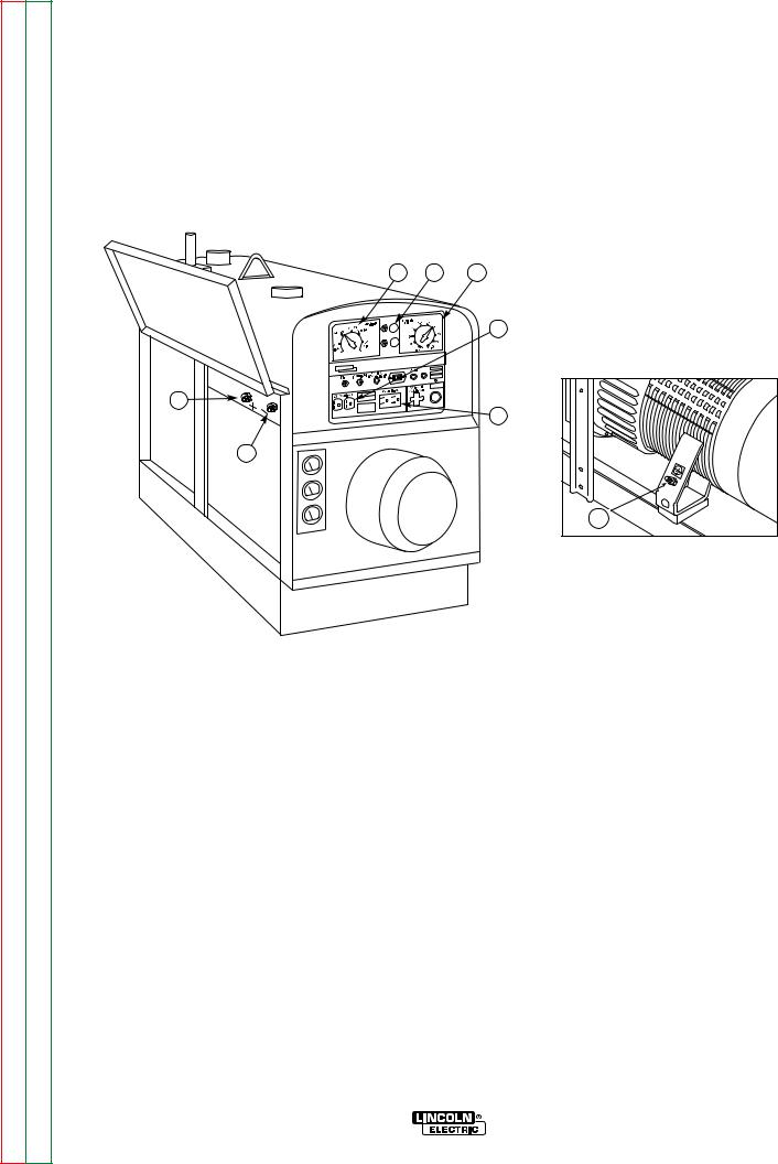
See Figure A.1 for the location of the 115 and 230 volt receptacles, weld output terminals, and ground stud.
WELDING CABLE CONNECTIONS
CABLE INSTALLATION AND CABLE SIZES
With the engine off, connect the electrode and work cables to the terminals located on the fuel tank mounting rail. (See size recommendations below.) For positive polarity, connect the electrode cable to the terminal marked Positive (+). For Negative polarity, connect the electrode cable to the Negative (-) terminal. These connections should be checked periodically and tightened if necessary.
•Loose connections will cause the output terminals to overheat. The terminals may eventually melt.
•Do not cross the welding cables at the output terminal connection. Keep the cables isolated and separate from one another.
When welding at a considerable distance from the welder, be sure you use ample size welding cables. Table A.1 lists recommended cable sizes and lengths for rated current and duty cycle. Length refers to the distance from the welder to the work and back to the welder. Cable diameters are increased for long cable lengths to reduce voltage drops.
Lincoln Electric offers a welding accessory kit with the properly specified welding cables. See the Accessories section of this manual for more information.
FIGURE A.1 - CLASSIC III & CLASSIC IIID OUTPUT CONNECTIONS |
|||
3 |
|
14 |
|
2 |
1. |
230 VAC RECEPTACLE |
|
1 |
2. |
115 VAC RECEPTACLE |
|
3. |
OUTPUT TERMINALS |
||
|
|||
|
4. |
GROUND STUD |
|
TABLE A.1 - RECOMMENDED COPPER WELDING CABLE SIZE AND LENGTH
TOTAL COMBINED LENGTH OF ELECTRODE AND WORK CABLES
|
|
|
Cable sizes for combined length of |
|
|
|
|
electrode plus work cable |
|
|
|
|
|
|
|
Amps |
Duty Cycle |
Up to 200 ft. |
200 to 250 ft. |
225 |
100% |
1 |
1/0 |
|
300 |
50% |
1/0 |
2/0 |
|
350 |
30% |
2/0 |
3/0 |
|
Classic III and IIID
Return to Section TOC |
Return to Master TOC |
Return to Section TOC |
Return to Master TOC |
Return to Section TOC |
Return to Master TOC |
Return to Section TOC |
Return to Master TOC |
A-7 |
A-7 |
INSTALLATION
MACHINE GROUNDING
According to the United States National Electrical Code, the frame of this portable generator is not required to be grounded and is permitted to serve as the grounding means for cord connected equipment plugged into its receptacles.
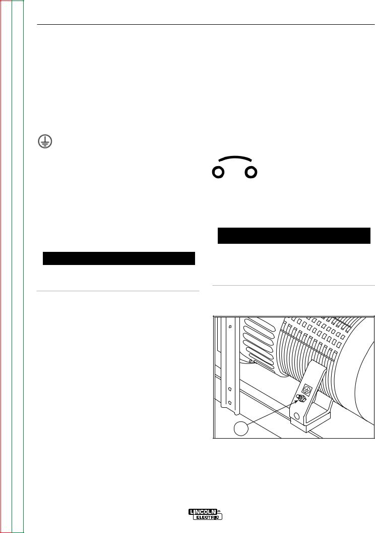
Some state, local or other codes or unusual operating circumstances may require the machine frame to be grounded. It is recommended that you determine the extent to which such requirements may apply to your particular situation and follow them explicitly. A
machine grounding stud marked with the symbol is provided on the welding generator frame foot.
(If an older portable welder does not have a grounding stud, connect the ground wire to an unpainted frame screw. See Figure A.2.
In general, if the machine is to be grounded, it should be connected with a #8 or larger copper wire to a solid earth ground such as a metal water pipe going into the ground for at least ten feet and having no insulated joints, or to the metal framework of a building which has been effectively grounded. The U.S. National Electrical Code lists a number of alternate means of grounding electrical equipment.
 WARNING
Do not ground the machine to a pipe that carries explosive or combustible material.
For further protection against electric shock, any electrical equipment connected to the generator receptacles must use a three-blade, grounded type plug or an Underwriter's Laboratories (UL) approved double insulation system with a two-blade plug. Lincoln offers an accessory plug kit that has the right type of plugs. See the Accessories section of this manual for details.
If you need ground fault protection for hand-held equipment, refer to the Accessories section of this manual for the GFCI Receptacle kit.
CIRCUIT BREAKERS
Classic III and Classic IIID welders are equipped with circuit breakers on the 115 and the 230 volt receptacles for overload protection. Under high heat a
breaker may tend to trip at lower loads than it would normally.
Operation with high ambient temperatures may cause the breakers to trip at lower than normal loads.
 CAUTION
Never bypass the circuit breakers. Without overload protection, the Classic III and Classic IIID could overheat and/or cause damage to the equipment being used.
When the Classic III and Classic IIID are mounted on a truck or a trailer, the machine generator ground stud MUST be securely connected to the metal frame of the vehicle. See Figure A.2. The ground stud is marked with the ground symbol.
AUXILIARY POWER RECEPTACLES, PLUGS, AND HAND-HELD EQUIPMENT
The AC auxiliary power, supplied as a standard, has a rating of 3.0 kVA of 115/230V AC (60 hertz).
With the 3.0 kVA, 115/230V AC auxiliary power, one 115V duplex and one 230V duplex grounding type receptacle are provided. The circuit is protected with circuit breakers.
The rating of 3.0 kVA permits a maximum continuous current of 13 amps to be drawn from the 230 volt duplex receptacle. Or a total of 26 amps can be drawn from the 115 volt duplex receptacle. The 115 volt duplex receptacle has a configuration which permits 15 amps to be drawn from either half of the receptacle.
The total combined load of all receptacles is not to exceed 3.0 kVA.
FIGURE A.2 - GROUND STUD LOCATION
1 |
1. GROUND STUD
Classic III and IIID

A-8
Return to Section TOC |
Return to Master TOC |
Return to Section TOC |
Return to Master TOC |
Return to Section TOC |
Return to Master TOC |
Return to Section TOC |
Return to Master TOC |
A-8
NOTES
Classic III and IIID

Return to Master TOC
Return to Master TOC
Return to Master TOC
Return to Master TOC
Section B-1 Section B-1
TABLE OF CONTENTS |
|
- OPERATION SECTION - |
|
Operation............................................................................................................................... |
Section B |
Safety Instructions....................................................................................................................... |
B-2 |
General Description .................................................................................................................... |
B-2 |
Recommended Applications ....................................................................................................... |
B-3 |
Welder ................................................................................................................................. |
B-3 |
Generator.............................................................................................................................. |
B-3 |
Operational Features and Controls ............................................................................................. |
B-3 |
Design Features .......................................................................................................................... |
B-3 |
Welding Capability....................................................................................................................... |
B-4 |
Limitations ................................................................................................................................. |
B-4 |
Controls and Settings.................................................................................................................. |
B-5 |
Welder/Generator Controls................................................................................................... |
B-5 |
Control of Welding Current ................................................................................................... |
B-6 |
Gasoline Engine Controls..................................................................................................... |
B-7 |
Diesel Engine Controls ......................................................................................................... |
B-8 |
Engine Operation ........................................................................................................................ |
B-9 |
Before Starting the Engine ................................................................................................... |
B-9 |
Starting the Gasoline Engine................................................................................................ |
B-9 |
Starting the Diesel Engine.................................................................................................... |
B-9 |
Stopping the Engine ........................................................................................................... |
B-10 |
Break-in Period ................................................................................................................... |
B-10 |
Welding Operation..................................................................................................................... |
B-11 |
DC Constant Current Stick or TIG Welding ........................................................................ |
B-11 |
DC Wire Feed Welding (Constant Voltage)......................................................................... |
B-12 |
Auxiliary Power.......................................................................................................................... |
B-13 |
Classic III and IIID

Return to Section TOC |
Return to Master TOC |
Return to Section TOC |
Return to Master TOC |
Return to Section TOC |
Return to Master TOC |
Return to Section TOC |
Return to Master TOC |
B-2 |
B-2 |
OPERATION
OPERATING INSTRUCTIONS
Read and understand this entire section before operating your Classic III or Classic IIID.
SAFETY INSTRUCTIONS
WARNING
Do not attempt to use this equipment until you have thoroughly read all the operation and maintenance manuals supplied with your machine. They include important safety precautions; detailed engine starting, operating, and maintenance instructions; and parts lists.
ELECTRIC SHOCK can kill.
• Do not touch electrically live parts or electrodes with your skin or wet clothing.
•Insulate yourself from the work and ground.
WARNING
ENGINE EXHAUST can kill.
• Use in open, well ventilated areas or vent exhaust to the outside.
• Do not stack anything on or near the engine.
MOVING PARTS can injure.
•Do not operate this equipment with any of its doors open or guards off.
•Stop the engine before servicing it.
•Keep away from moving parts.
Only qualified personnel should install, use, or service this equipment.
• Always wear dry insulating gloves.
FUMES AND GASES can be dangerous.
 • Keep your head out of fumes.
• Use ventilation or exhaust to remove fumes from breathing zone.
WELDING SPARKS can cause 
 fire or explosion.
•Keep flammable material away.
•Do not weld on containers that have held combustibles.
GENERAL DESCRIPTION
The Classic III and Classic IIID are heavy duty engine driven DC arc welding power sources capable of providing constant current output for stick welding or DC TIG welding. These welders are wound with all copper coils and feature improved door latches and stainless steel hinges. With the addition of the optional K623-1 Wire Feed Module, the welders will provide constant voltage output for running the LN-7, LN-23P, or LN-25 wire feeders.
The Classic III and Classic IIID have a current range of 40-350 DC amps with a 50% duty cycle at 300 amps/32 volts. The units are also capable of providing 3.0 kVA of 115/230 volt, 60 Hertz AC auxiliary power.
The Classic III uses the Continental TM27 four-cylin- der, industrial water-cooled gasoline engine, and the Classic IIID uses the Continental TMD27 industrial water cooled diesel engine.
ARC RAYS can burn.
• Wear eye, ear, and body protection.
Classic III and IIID

Return to Section TOC |
Return to Master TOC |
Return to Section TOC |
Return to Master TOC |
Return to Section TOC |
Return to Master TOC |
Return to Section TOC |
Return to Master TOC |
B-3 |
B-3 |
OPERATION
RECOMMENDED APPLICATIONS
WELDER
The Classic III and Classic IIID provide excellent constant current DC welding output for stick (SMAW) welding and for DC TIG welding. When equipped with the wire feed module, they also offer constant voltage output for DC semiautomatic wire feed welding. For more details on using the machine as a welder, see Welding Operation in the Operation section of this manual.
GENERATOR
The Classic III and Classic IIID are also capable of providing 3.0 kVA of 115/230 volts of 60 Hertz AC auxiliary power.
OPERATIONAL FEATURES AND CONTROLS
The Classic III and Classic IIID are designed for simplicity. Therefore, it has very few operating controls. Two controls are used for welding operations:
•A five-position CURRENT RANGE SELECTOR switch selects current output ranges for constant current stick or TIG applications and constant voltage wire feed applications (with optional Wire Feed Module - see the Accessories section)
•A FINE CURRENT ADJUSTMENT control for fine adjustment of current from minimum to maximum within each range
Controls for the engine include a two-position IGNITION ON/OFF toggle switch, a START pushbutton, and a two-position IDLER switch that selects engine speed for welding or auxiliary power applications. See Engine Operation in the Operation section of this manual for details about starting, running, stopping, and breaking in the engine.
DESIGN FEATURES
•All copper windings for long life and dependable operation.
•Constant current DC Stick welding (SMAW) process capability with output range from 40 - 350 DC amps.
•Constant current DC TIG Welding with output across the entire range of settings.
•Work and Electrode welding cable mounting terminals.
•Separate ground stud for safe connection of case to earth ground.
•Duplex, 230 volt auxiliary power receptacle.
•Duplex, 115 volt auxiliary power receptacle.
•Integrated generator output overload protection through four 15 amp circuit breakers.
•Electric starting.
•Battery Charging Ammeter.
•Engine Oil Pressure Gauge. (Classic III D only)
•Engine Hour Meter for determining periodic maintenance.
•Top-of-the-line 38.9 HP Continental gasoline (Classic III) or 45 HP Continental diesel engine (Classic IIID).
•Top-mounted 15 gallon (57.0 litter) fuel tank with convenient top fill.
•Automatic engine shutdown protection for low oil pressure or high engine coolant temperature (Classic IIID).
•Automatic engine idler goes to low idle approximately 15 seconds after welding for greater fuel economy; includes high idle switch.
Classic III and IIID

Return to Section TOC |
Return to Master TOC |
Return to Section TOC |
Return to Master TOC |
Return to Section TOC |
Return to Master TOC |
Return to Section TOC |
Return to Master TOC |
B-4 |
B-4 |
OPERATION
WELDING CAPABILITY
The Classic III and Classic IIID are rated 300 amps, 32 volts constant current DC at 50% duty cycle based on a ten minute time period. Longer duty cycles at lower output currents are possible.
The current is continuously variable from 40 to 350 amps DC.
LIMITATIONS
The Classic III and Classic IIID are not recommended for any processes besides those that are normally performed using DC stick welding (SMAW) and DC TIG welding. Specific limitations on using the Classic III and Classic IIID for these processes are described in the Welding Operation section of this manual. Constant voltage welding is available with the optional Wire Feed Module.
Classic III and IIID
Return to Section TOC |
Return to Master TOC |
Return to Section TOC |
Return to Master TOC |
Return to Section TOC |
Return to Master TOC |
Return to Section TOC |
Return to Master TOC |
B-5 |
B-5 |
|
|
OPERATION |
|
|
CONTROLS AND SETTINGS |
|
|
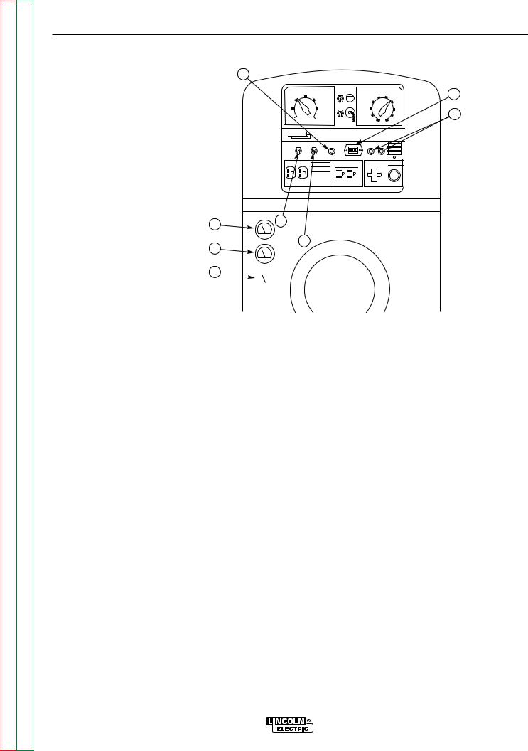
The welder/generator controls are located on the |
the case front. Welding output terminals and ground |
|
Output Control Panel of the machine case front. |
stud are located on the machine left side, under the |
|
Engine idler control and start/stop controls are also on |
door. See Figures B.1, B.2 and B.3 and the explana- |
|
|
tions that follow. |
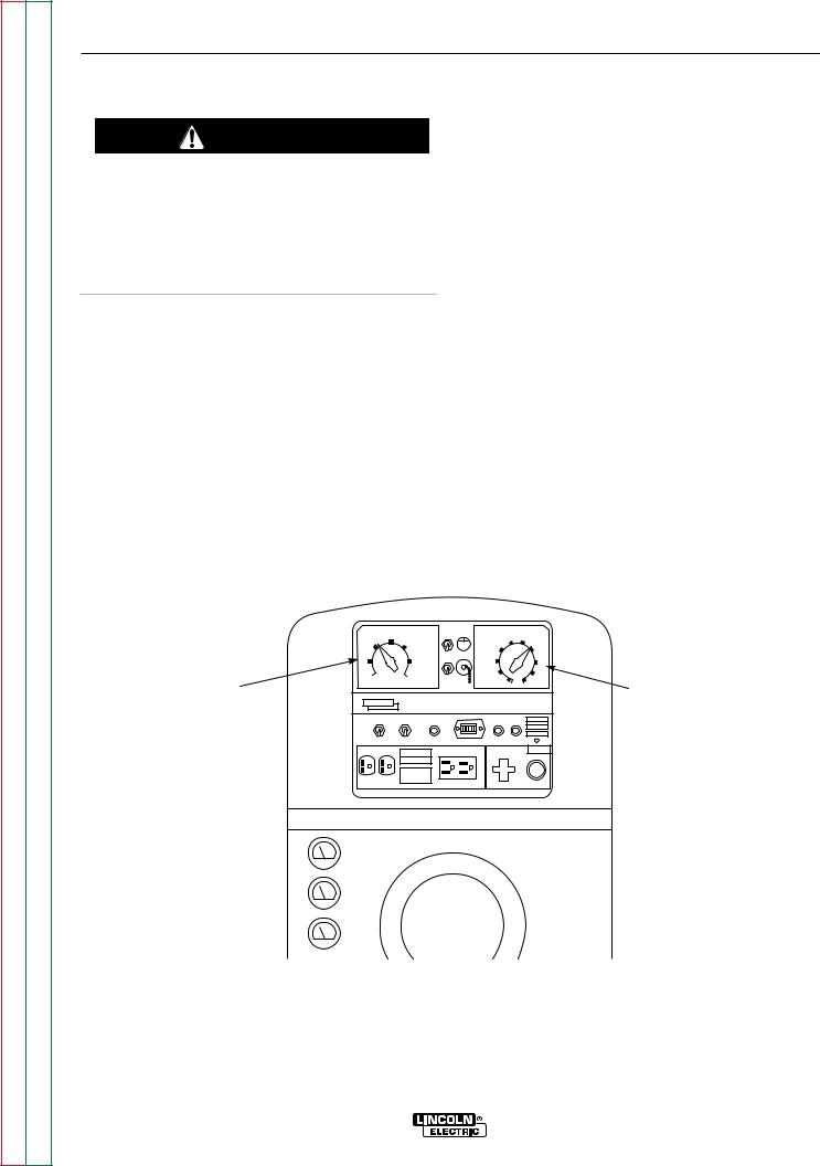
FIGURE B.1 – OUTPUT CONTROLS
1 |
8 |
2 |
|
|
3 |
6 |
|
4 |
|
|
|
5 |
|
|
|
|
17 |
|
1. |
CURRENT RANGE SELECTOR |
|
2. |
FINE CURRENT ADJUSTMENT |
|
3. |
230 VOLT DUPLEX RECEPTACLE |
|
4. |
115 VOLT DUPLEX RECEPTACLE |
|
5. |
WELD OUTPUT TERMINAL (–) |
|
6. |
WELD OUTPUT TERMINAL (+) |
|
7. |
GROUND STUD |
WELDER/GENERATOR CONTROLS |
8. |
OPTIONAL WIRE FEED MODULE |
|
CONTROLS |
|
|
|
See Figure B.1 for the location of the following features:
1. CURRENT RANGE SELECTOR: Selects ranges |
4. |
115 VOLT DUPLEX RECEPTACLE: Connection |
|
of continuous current output for constant current |
|||
stick or TIG applications and constant voltage wire |
|
point for supplying 115 volt power to operate one or |
|
feed applications (with optional Wire Feed Module). |
|
two electrical devices. |
|
See Control of Welding Current for more informa- |
5. |
WELD OUTPUT TERMINAL (–) WITH FLANGE |
|
tion. |
|||
|
NUT: Provides the connection point for either the |
||
|
|
||
2. FINE CURRENT ADJUSTMENT: Allows fine |
|
electrode holder or the work cable. |
|
adjustment of current within the selected output |
6. |
WELD OUTPUT TERMINAL (+) WITH FLANGE |
|
range. See Control of Welding Current for more |
|||
|
NUT: Provides the connection point for either the |
||
|
|
information. |
electrode holder or the work cable. |
|
|
||
3. 230 VOLT DUPLEX RECEPTACLE: Connection |
7. GROUND STUD: Provides a connection point for |
|
point for supplying 230 volt power to operate one or |
||
connecting the machine case to earth ground for the |
||
two electrical devices. |
||
safest grounding procedure. |
||
|
Classic III and IIID
Return to Section TOC |
Return to Master TOC |
Return to Section TOC |
Return to Master TOC |
Return to Section TOC |
Return to Master TOC |
Return to Section TOC |
Return to Master TOC |
B-6 |
B-6 |
OPERATION
CONTROL OF WELDING CURRENT
CAUTION
•DO NOT turn the CURRENT RANGE SELECTOR while welding because the current may arc between the contacts and damage the switch.
•DO NOT attempt to set the CURRENT RANGE SELECTOR between the five points designated on the nameplate.
See Figure B.2. The CURRENT RANGE SELECTOR provides five overlapping current ranges. The FINE CURRENT ADJUSTMENT adjusts the current from minimum to maximum within each range. Open circuit voltage is also controlled by the FINE CURRENT ADJUSTMENT, permitting control of the arc characteristics.
A high open circuit voltage setting provides the soft "buttering" arc with best resistance to pop-outs preferred for most welding. To get this characteristic, set the CURRENT RANGE SELECTOR to the lowest setting that still provides the current you need and set the FINE CURRENT ADJUSTMENT near maximum. For example: to obtain 175 amps and a soft arc, set the CURRENT RANGE SELECTOR to the 190 -120 position and then adjust the FINE CURRENT ADJUSTMENT for 175 amps.
When a forceful "digging" arc is required, usually for vertical and overhead welding, use a higher CURRENT RANGE SELECTOR setting and lower open circuit voltage. For example: to obtain 175 amps and a forceful arc, set the CURRENT RANGE SELECTOR to 240160 position and the FINE CURRENT ADJUSTMENT setting to get 175 amps.
Some arc instability may be experienced with EXX10 electrodes when trying to operate with long arc techniques at settings at the lower end of the open circuit voltage range.
FIGURE B.2 – CURRENT CONTROLS
|
|
CURRENT RANGE |
FINE CURRENT |
|
|
|
|
190-120 |
SELECTION |
ADJUSTMENT |
50 |
|
|
|
|
|
60 |
|
||
|
240-160 |
130-80 |
|
|
||
|
|
70 |
40 |
|
||
|
|
|
|
|
||
CURRENT |
220 |
90 |
|
80 |
30 |
FINE |
MAX |
MIN |
|
90 |
20 |
||
RANGE |
|
|
|
100 |
10 |
CURRENT |
SELECTOR |
|
|
|
|
|
ADJUSTMENT |
|
IDLER IGNITION |
ENGINE |
START |
|
|
|
|
PROTECTION |
|
|
|||
|
230 VOLT AC |
|
115 VOLT AC |
REMOTE |
|
|
|
|
CONTROL |
|
|
||
|
|
|
|
|
|
|
Classic III and IIID
Return to Section TOC |
Return to Master TOC |
Return to Section TOC |
Return to Master TOC |
Return to Section TOC |
Return to Master TOC |
Return to Section TOC |
Return to Master TOC |
B-7 |
B-7 |
OPERATION
FIGURE B.3 – GASOLINE ENGINE CONTROLS
|
|
|
|
|
CURRENT RANGE |
|
FINE CURRENT |
|
5 |
|
|
|
|
190-120 |
SELECTION |
|
ADJUSTMENT |
50 |
|||
|
|
|
|
|
|
60 |
||||
|
|
|
240-160 |
|
130-80 |
|
|
|||
|
|
|
|
|
|
|
|
70 |
40 |
|
|
|
|
220 |
|
90 |
|
|
80 |
30 |
4 |
|
|
|
MAX |
|
MIN |
|
|
90 |
20 |
|
|
|
|
|
|
|
|
|
|||
|
|
|
|
|
|
|
|
100 |
10 |
|
|
|
|
IDLER |
IGNITION |
OIL |
|
START |
|
|
|
|
|
|
PRESSURE |
|
|
|||||
|
|
|
|
|
|
|
|
|
||
|
|
|
230 VOLT AC |
|
|
115 VOLT AC |
REMOTE |
|
|
|
|
|
|
|
|
CONTROL |
|
|
|||
1. |
IDLER CONTROL TOGGLE |
|
|
|
|
|
|
|
|
|
|
|
|
|
|
|
|
|
|
||
|
SWITCH |
|
|
|
|
|
|
|
|
|
2. |
IGNITION TOGGLE SWITCH |
|
|
|
|
|
|
|
|
|
3. |
CHOKE |
|
|
|
|
|
|
|
|
|
4. |
START PUSHBUTTON |
|
|
|
|
|
|
|
|
|
5. |
ENGINE HOUR METER |
6 |
1 |
|
|
|
|
|
|
|
6. |
AMMETER |
|
|
|
|
|
|
|
||
|
|
|
2 |
|
|
|
|
3 |
|
|
GASOLINE ENGINE CONTROLS (CLASSIC III)
See Figure B.3 for the location of the following features:
1.IDLER CONTROL TOGGLE SWITCH: Adjusts the running speed of the engine. The switch has two positions, "HIGH" and "AUTO." In "HIGH," the engine runs continuously at high idle. In "AUTO," the idler control works as follows:
Welding: The engine accelerates to high speed when the electrode touches the work and strikes a welding arc. The engine returns to low idle approximately 15 seconds after welding stops, as long as no auxiliary power is being drawn.
Auxiliary Power: The engine accelerates to high speed when power is drawn at the receptacles for lights or tools. The engine returns to low idle approximately 15 seconds after demand for auxiliary power stops.
2.IGNITION CONTROL TOGGLE SWITCH: Has two positions, ON and OFF. When the switch is in the ON position, the engine can be started by pressing the START pushbutton. When the switch is placed in the OFF position, the engine stops.
3.CHOKE: Provides a richer air/fuel mixture for cold engine starting conditions. See the topic Engine Operation for details on setting the choke.
4.START PUSHBUTTON: Press the START button to start the engine. The IGNITION switch must be in the ON position.
NOTE: If you press the START pushbutton when the engine is running, you may damage the engine flywheel gear or starter motor.
5.ENGINE HOUR METER: Records engine running time. Use the meter to determine when to perform required maintenance.
6.AMMETER: Shows whether the charging circuit is performing its job of charging the battery when the engine is running. The meter will register discharge during starting, but then the needle should return to a position slightly toward positive during running. The needle will hold position in the center when the engine stops.
Classic III and IIID
Return to Section TOC |
Return to Master TOC |
Return to Section TOC |
Return to Master TOC |
Return to Section TOC |
Return to Master TOC |
Return to Section TOC |
Return to Master TOC |
B-8 |
|
|
|
B-8 |
|
OPERATION |
|
|
|
||
FIGURE B.4 – DIESEL ENGINE CONTROLS |
|
||||
3 |
|
|
|
|
|
|
CURRENT RANGE |
FINE CURRENT |
|
5 |
|
190-120 |
SELECTION |
ADJUSTMENT |
50 |
||
|
60 |
||||
240-160 |
130-80 |
||||
70 |
40 |
||||
|
|
|
|||
220 |
90 |
80 |
30 |
4 |
|
MAX |
MIN |
90 |
20 |
||
|
|
||||
|
|
100 |
10 |
|
|
IDLER IGNITION RESET |
START |
|
|
||
230 VOLT AC |
115 VOLT AC |
REMOTE |
|
|
|
1. IDLER CONTROL TOGGLE |
|
CONTROL |
|
|
|
SWITCH |
|
|
|
|
|
2.IGNITION TOGGLE SWITCH
3.RESET BUTTON
4.START PUSHBUTTONS
5.ENGINE HOUR METER
6. |
OIL PRESSURE GAUGE |
8 |
1 |
7. |
AMMETER |
|
|
|
2 |
||
8. |
TEMPERATURE GAUGE |
7 |
|
|
|
|
6 

DIESEL ENGINE CONTROLS (CLASSIC IIID)
See Figure B.4 for the location of the following features:
1.IDLER CONTROL TOGGLE SWITCH: Adjusts the running speed of the engine. The switch has two positions, "HIGH" and "AUTO." In "HIGH," the engine runs continuously at high idle. In "AUTO," the idler control works as follows:
Welding: The engine accelerates to high speed when the electrode touches the work and strikes a welding arc. The engine returns to low idle approximately 15 seconds after welding stops, as long as no auxiliary power is being drawn.
Auxiliary Power: The engine accelerates to high speed when power is drawn at the receptacles for lights or tools. The engine returns to low idle approximately 15 seconds after demand for auxiliary power stops.
2.IGNITION CONTROL TOGGLE SWITCH: Has two positions, ON and OFF. When the switch is in the ON position, the diesel engine can be started by pressing the START pushbutton. When the switch is placed in the OFF position, the engine stops.
3.RESET BUTTON: Resets engine protection circuit. Press this button before starting the diesel engine.
4.START AND GLOW PLUG PUSHBUTTONS:
Press the START button to start the diesel engine. The IGNITION switch must be in the ON position.
NOTE: If you press the START pushbutton when the engine is running, you may damage the engine flywheel gear or starter motor.
5.ENGINE HOUR METER: Records engine running time. Use the meter to determine when to perform required maintenance.
6.OIL PRESSURE GAUGE: Indicates engine oil pressure. If no oil pressure shows on the gauge within 30 seconds after startup, the engine should be stopped by placing the IGNITION switch in the OFF position.
7.AMMETER: Shows whether the charging circuit is performing its job of charging the battery when the engine is running. The meter will register discharge during starting, but then the needle should return to a position slightly toward positive during running. The needle will hold position in the center when the engine stops.
8.TEMPERATURE GAUGE: Indicates temperature of engine coolant.
Classic III and IIID
Return to Section TOC |
Return to Master TOC |
Return to Section TOC |
Return to Master TOC |
Return to Section TOC |
Return to Master TOC |
Return to Section TOC |
Return to Master TOC |
B-9 |
|
B-9 |
|||
|
|
|
OPERATION |
|
|
|
ENGINE OPERATION |
|
STARTING THE CLASSIC III CONTINEN- |
||
|
|
|
|
TAL TM27 GASOLINE ENGINE |
|
|
|
WARNING |
|
||
|
|
|
NOTE: Remove all loads connected to the AC power |
||
|
|
|
|
receptacles before starting the engine. |
|
DO NOT RUN THE ENGINE AT EXCESSIVE SPEEDS. The maximum allowable high idle speed for the Classic III and Classic IIID is 1800 RPM, no load. Do NOT increase the idle speed on the engine. Severe personal injury and damage to the machine can result if it is operated at speeds above the maximum rated speed.
1.Turn the IDLER switch to “HIGH”.
2.Turn the IGNITION switch to ON.
3.Pull out the CHOKE control.
4.Press the START button.
5.If the engine fails to start in 60 seconds, wait 30 seconds before repeating the above procedure.
Read and understand all safety instructions included in the Continental engine instruction manual that is shipped with your welder.
BEFORE STARTING THE ENGINE
Check and fill the engine oil level:
1. Be sure the machine is on a level 
 surface.
2.Remove the engine oil dipstick and wipe it with a clean cloth. Reinsert the dipstick and check the level on the dipstick. See Figure D.1 in the Maintenance section of this manual.
3.Add oil (if necessary) to bring the level up to the full mark. Do not overfill.
4.Replace the dipstick.
Check and fill the engine fuel tank:
WARNING
Do not add fuel near an open flame, welding arc or when the engine is running. Stop the engine and allow it to cool before refueling to prevent spilled fuel from vaporizing on contact with hot engine parts and igniting. Do not
spill fuel when filling tank. If fuel is spilled, wipe it up and do not start engine until fumes have been eliminated.
1.Remove the fuel tank cap.
2.Fill the tank to allow approximately 1/4 inch (5 mm) of tank space for fuel expansion. DO NOT FILL THE TANK TO THE POINT OF OVERFLOW.
3.Replace the fuel tank cap and tighten securely.
NOTE: Purchase fuel in quantities that will be used within 30 days, to assure freshness.
6.Allow engine to run at high idle speed for several minutes to warm the engine. Cold engines tend to run at a speed too slow to supply the voltage required for proper automatic idler operation.
7.As engine warms, slowly return the CHOKE control to the OFF position.
STARTING THE CLASSIC IIID CONTINENTAL TMD27 ENGINE
NOTE: Remove all loads connected to the AC power receptacles before starting the engine.
1.Place the IDLER switch in the "HIGH" position and the IGNITION switch in the ON position. Press the RESET button.
2.Press the GLOW PLUG button for 10 to 20 seconds.
3.While holding down the GLOW PLUG button, press the START button. Release both buttons when the engine starts.
NOTE: If the engine fails to start in 60 seconds, the RESET button will pop out. Wait 30 seconds then repeat step 1, 2, and 3.
4.When the engine starts running, observe the oil pressure. If no pressure shows within 30 seconds, stop the engine and consult the engine operating manual.
5.Allow the engine to run at high idle for several minutes to warm the engine prior to welding. Extreme cold weather may require longer glow plug operation.
WARNING
Under NO conditions should ether or other starting fluids be used in conjunction with the glow plugs. This may cause an explosion or fire!
Classic III and IIID

Return to Section TOC |
Return to Master TOC |
Return to Section TOC |
Return to Master TOC |
Return to Section TOC |
Return to Master TOC |
Return to Section TOC |
Return to Master TOC |
B-10 |
B-10 |
OPERATION
STOPPING THE ENGINE (GASOLINE OR DIESEL)
1. Place the IGNITION switch in the OFF position.
At the end of each day’s welding, drain accumulated dirt and water from the sediment bowl under the fuel tank and from the fuel filter (diesel engine, Classic IIID) per instructions in the engine manufacturer’s operating manual. Refill the fuel tank to minimize moisture condensation in the tank. Also, running out of fuel tends to draw dirt into the fuel system. Check the crankcase oil level.
When hauling the welder between job sites, close the fuel feed valve beneath the tank. In gasoline engines, failing to turn off the fuel when traveling can cause carburetor flooding and difficult starting at the new job site.
In diesel engines, if the fuel supply is cut off or runs out while the fuel pump is operating, air may be entrapped in the fuel distribution system. See “How to Eliminate Air From the Fuel System” in the Maintenance section.
BREAK-IN PERIOD
When an engine is started for the first time, some of the oil will be needed to fill the passages of the lubricating system. Therefore, on initial starting, run the engine for about five minutes and then stop the engine and recheck the oil. If the level is down, fill to the full mark again.
The engine controls were properly set at the factory and should require no adjusting when received.
Any engine will use a small amount of oil during its break-in period. For the gasoline or diesel engine on the Classic III or Classic IIID, break-in is about 200 running hours.
Check the oil twice a day during break-in. Change the oil and oil filter cartridge after the first 25 hours of operation. Also change the fuel filter cartridge on the diesel engine. For more details, see the Maintenance section of this manual.
 CAUTION
During break-in, subject the Classic III or Classic IIID to only moderate loads. Avoid long periods running at idle. Before stopping the engine, remove all loads and allow the engine to cool several minutes.
Classic III and IIID
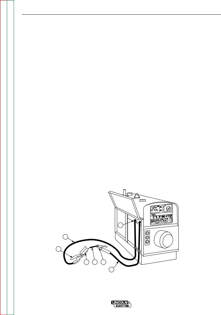
Return to Section TOC |
Return to Master TOC |
Return to Section TOC |
Return to Master TOC |
Return to Section TOC |
Return to Master TOC |
Return to Section TOC |
Return to Master TOC |
B-11 |
B-11 |
OPERATION
WELDING OPERATION
TO USE THE CLASSIC III OR CLASSIC IIID FOR DC CONSTANT CURRENT STICK OR TIG WELDING:
1.Remove the flange nuts from the weld output terminals and place the work and electrode welding cables over the terminals. See Figure B.5. Replace and tighten the flange nuts securely. Be sure the connections are tight.
2.Select the appropriate electrode.
3.Attach the work clamp securely to the work you are welding.
4.Insert the electrode into the electrode holder.
5.Start the engine. See Engine Operation in this section of the manual.
6.Set the Idler Switch to “AUTO.”
7.Set the CURRENT RANGE SELECTOR to a setting equal to or slightly higher than the desired welding current.
8.Set the FINE CURRENT ADJUSTMENT to the setting that gives the best arc characteristics for the range selected. See Control of Welding Current in this section of the manual.
9.Strike an arc and begin welding.
After you finish welding:
1.Stop the engine. See Engine Operation in this section of the manual.
2.Allow the electrode and work to cool completely.
3.Remove the work clamp from the work.
4.Remove any remaining piece of electrode from the electrode holder.
FIGURE B.5 – WELDING CIRCUIT CONNECTIONS FOR STICK WELDING
1. FLANGE NUT
2. ELECTRODE CABLE
3. ELECTRODE HOLDER
4. ELECTRODE
5. WORK
6. WORK CLAMP
7. WORK CABLE
1
7
6
5 |
4 |
3 |
2
Classic III and IIID

Return to Section TOC |
Return to Master TOC |
Return to Section TOC |
Return to Master TOC |
Return to Section TOC |
Return to Master TOC |
Return to Section TOC |
Return to Master TOC |
B-12 |
B-12 |
OPERATION
TO USE THE CLASSIC III OR CLASSIC IIID FOR DC WIRE FEED WELDING (CONSTANT VOLTAGE WITH WIRE FEED MODULE):
1.Connect the LN-25, LN-23P, or LN-7 Wire Feeder. Follow the installation instructions provided with the wire feeder.
2.Set the machine for CV operation.
3.Start the engine. See Engine Operation in this section of the manual.
4.Set the Idler Switch to "AUTO."
5.Set the CURRENT RANGE SELECTOR to a setting appropriate for your wire size and wire feed speed. See Table B.1 for recommended settings.
6.Set the VOLTAGE ADJUSTMENT to the setting that gives the best arc characteristics for the range selected.
7.Pull the gun trigger and begin welding.
TABLE B.1
RANGE SETTINGS FOR WIRE SIZE/SPEED
Diameter (inches) |
Wire Speed Range |
Appropriate Current Range |
|
|
(inches/minute) |
|
|
.035 |
80-110 |
80 to 130 Amps |
|
.045 |
70-130 |
120 to 190 Amps |
|
.068 |
40-90 |
150 to 240 Amps |
|
|
|
|
|
Classic III and IIID

Return to Section TOC |
Return to Master TOC |
Return to Section TOC |
Return to Master TOC |
Return to Section TOC |
Return to Master TOC |
Return to Section TOC |
Return to Master TOC |
B-13 B-13
OPERATION
AUXILIARY POWER
WARNING
Be sure that any electrical equipment plugged into the generator AC power receptacles can withstand a ±10% voltage and a ±3% frequency variation.
The AC auxiliary power, supplied as a standard, has a rating of 3.0 kVA of 115/230V AC power (60 hertz).
One 115V duplex and one 230V duplex grounding type receptacle are provided. The circuit is protected with circuit breakers.
The rating of 3.0 kVA permits a maximum continuous current of 13 amps to be drawn from the 230 volt duplex receptacle. Or a total of 26 amps can be drawn from the 115 volt duplex receptacle. The 115 volt duplex receptacle permits 15 amps to be drawn from either half. The total combined load of all receptacles must not exceed 3.0 kVA.
An optional power plug kit is available. When this kit is specified, the customer is supplied with a plug for each receptacle. See the Accessories section of this manual.
An optional GFCI 115 volt receptacle kit is also available. Note that the use of this GFCI kit reduces available current to a total of 20 Amps of available 115 volt power. See the Accessories section of this manual.
To use the generator as an auxiliary power supply:
1.Start the diesel engine. See Engine Operation in this section of the manual.
2.Set the IDLER switch to AUTO. Set the CURRENT RANGE SELECTOR to “MAX.” SeeFigure B.1.
3.Plug the load(s) into the appropriate 115 volt or 230 volt power receptacle.
Classic III and IIID

B-14
Return to Section TOC |
Return to Master TOC |
Return to Section TOC |
Return to Master TOC |
Return to Section TOC |
Return to Master TOC |
Return to Section TOC |
Return to Master TOC |
B-14
NOTES
Classic III and IIID

Return to Master TOC
Return to Master TOC
Return to Master TOC
Return to Master TOC
Section C-1 Section C-1
TABLE OF CONTENTS - ACCESSORIES -
Accessories........................................................................................................................... |
Section C |
Options/Accessories ................................................................................................................... |
C-2 |
TIG Welding Accessories............................................................................................................ |
C-3 |
Semiautomatic FCAW and MIG Welding Accessories ............................................................... |
C-3 |
Connection of Lincoln Electric Wire Feeders.............................................................................. |
C-4 |
Connection of the LN-7 using K867 Universal Adapter ....................................................... |
C-4 |
Connection of the LN-7 using K584 Input Cable Assembly ................................................. |
C-5 |
Connection of the LN-25 using K867 Universal Adapter ..................................................... |
C-6 |
Connection of the LN-25 “Across the Arc” ........................................................................... |
C-7 |
Connection of the LN-23P using the K1350-1 Adapter Kit .................................................. |
C-8 |
Connection of the K488 SG Control Module and K487 Magnum Spool Gun ...................... |
C-9 |
Classic III and IIID

Return to Section TOC |
Return to Master TOC |
Return to Section TOC |
Return to Master TOC |
Return to Section TOC |
Return to Master TOC |
Return to Section TOC |
Return to Master TOC |
C-2 |
C-2 |
ACCESSORIES
OPTIONS/ACCESSORIES
The following options/accessories are available for your Classic III or Classic IIID from your local Lincoln Distributor.
Trailer (K913) - Two-wheeled trailer for in-plant and yard towing. Various hitches and accessories are available. For highway use, consult applicable federal, state, and local laws.
Trailer (K780) - Two-wheeled trailer with brakes, lights, and fenders. (For highway use, consult applicable state and local laws.)
Power Plug Kit (K802-C) - Provides a plug for each auxiliary receptacle.
Linc Thaw™ Contr ol Unit (L2964-5) - Includes meter and fuses to protect the welder when thawing frozen water pipes.
WARNING
PIPE THAWING is not a CSA approved procedure. If not done properly, it can result in fire, explosion, damage to pipes, wiring, and the welder as well as other unsafe or hazardous conditions. Do not use a welder to thaw pipes before reviewing Lincoln Bulletin E695.1 (dated October 1987 or later).
Wire Feed Module - (K623-1) - Provides constant voltage output for semiautomatic welding. Includes remote for CV mode and internal “Cold Tip Contactor.”
Accessory Kit (K703) - Includes the following:
•Electrode cable
•Work cable
•Headshield
•Work clamp
•Insulated electrode holder
Remote Control - (K924-1) - Includes a receptacle switch and control box with 100 ft. (7.5 meters) of 4- conductor cable. Allows fine current and OCV to be controlled remotely.
GFCI Receptacle Kit (K896-2) - Includes a UL approved 115 volt ground fault circuit interrupter receptacle (duplex type) with covers and installation instructions. Each half of the receptacle is rated 15 amps, but the maximum total current from the GFCI duplex is limited to 20 amps. The GFCI receptacle replaces the factory installed 115 volt duplex receptacle.
Classic III and IIID
 Loading...