


SL580
Table of contents
 Loading...
Doc 01-G0547
Rev D
-
Installation and Maintenance
Instructions
Model SL580
Heavy Duty Slide Gate Operator
Model SL590
Heavy Duty, Harsh Environment
Slide Gate Operator

2 Contents
Doc 01-G0547
Rev D
Contents
General Information________________________________________________________ 4
Supplied Parts _______________________________________________________________________ 4
Model Classifications _________________________________________________________________ 4
Specifications _______________________________________________________________________ 5
Operator Dimensions__________________________________________________________________ 6
Cycle Rates _________________________________________________________________________ 6
Safety Information _________________________________________________________ 7
Safety Instructions____________________________________________________________________ 7
Safety Precautions for Open-Roller Gates and Ornamental “Grill Type” Gates ____________________ 9
Pre-Installation Check-List _________________________________________________ 11
Wiring Specifications ________________________________________________________________ 11
Features_________________________________________________________________ 13
Operator Features ___________________________________________________________________ 13
System Features_____________________________________________________________________ 15
Installation ______________________________________________________________ 17
Step 1: Set Up Post or Pad Mounting ___________________________________________________ 17
Step 2: Mounting the Operator________________________________________________________ 19
Step 3: Gate Brackets _______________________________________________________________ 19
Step 4: Drive Chain_________________________________________________________________ 20
Electrical Disconnect Switch___________________________________________________________ 21
Step 5: Electrical Power Connections ___________________________________________________ 21
Step 6: Limit Switch Adjustments _____________________________________________________ 22
Programming ____________________________________________________________ 23
Switch #1: Operator Programming ______________________________________________________ 23
Switch #2: Timer to Close_____________________________________________________________ 24
Adjustments and Check Out_________________________________________________ 25
Clutch Adjustment___________________________________________________________________ 25
Preliminary System Check Out_________________________________________________________ 25
Controls and Accessory Installation __________________________________________ 26

Contents 3
Doc 01-G0547
Rev D
Troubleshooting___________________________________________________________27
1. Power___________________________________________________________________________ 27
2. Accessories ______________________________________________________________________ 28
3. Primary Voltage Circuit ____________________________________________________________ 28
4. Low Voltage Circuit _______________________________________________________________ 29
Gear Reducer _______________________________________________________________________ 30
General Reference Information_________________________________________________________ 30
Features and Program Troubleshooting Review____________________________________________ 30
Required Maintenance – Normal Usage _______________________________________31
SL580/590 Parts List & Drawings ____________________________________________32
SL580 Exploded View _______________________________________________________________ 32
SL580 Parts List ____________________________________________________________________ 33
SL590 Exploded View _______________________________________________________________ 35
SL590 Parts List ____________________________________________________________________ 36
Warranty Policy___________________________________________________________38
4 General Information
Doc 01-G0547
Rev D
General Information
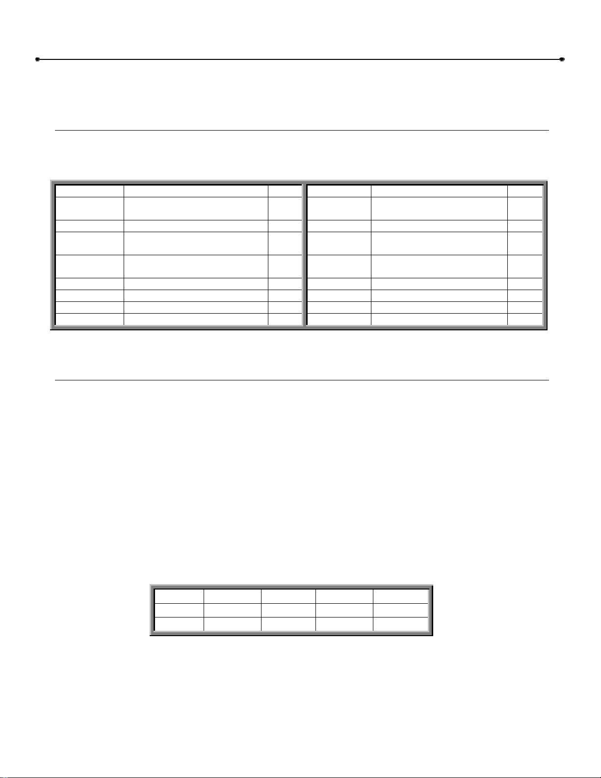
Supplied Parts
Inspect the operator for possible shipping damage and shortage of parts. Some ordered accessories
may be packed separately.
For Models SL580 & SL590
PART # DESCRIPTION QTY. PART # DESCRIPTION QTY.
01-G0547 SL580 & SL590 MANUAL 1 82-QN43-12
7/16-14 x 3/4 SQUARE
HEAD BOLT
4
01-G0582 GATE SAFETY INSTR. 1 84-RH-50 1/2-13 HEX NUT 4
02-401-SP STOP BUTTON 1 84-WH-31
5/16-18 SERRATED
FLANGED LOCK NUT
8
10-3209 GATE BRACKET 2 84-WH-38
3/8-16 SERRATED
FLANGED LOCK NUT
8
11-3503 TAKE UP BOLT 2 85-FW-38 3/8 FLAT WASHER 8
19-3025 #50 CHAIN 1 85-FW-50 1/2 FLAT WASHER 4
80-3001 5/16-18 U-BOLT 4 85-LS-50 1/2 SPLIT LOCK WASHER 4
80-3002 3/8-16 U-BOLT 4 40-3505 WARNING SIGN 2
Table 1
Model Classifications
RESIDENTIAL VEHICULAR GATE
OPERATOR: CLASS 1
A vehicular gate operator or system intended
for use in a home of one to four single family
dwelling or a garage or parking area.
COMMERCIAL/GENERAL ACCESS
VEHICULAR GATE OPERATOR:
CLASS 2
A vehicular gate operator or system intended
for use in a commercial location or building
such as a multi-family housing unit of five or
more single family units, hotel, garages, retail
store, or other building servicing the general
public.
INDUSTRIAL/LIMITED ACCESS VEHICULAR
GATE OPERATOR: CLASS 3
A vehicular gate operator or system intended for use
in an industrial location or building such as a factory
or loading dock area or other locations not intended
to service the general public.
RESTRICTED ACCESS VEHICULAR GATE
OPERATOR – CLASS 4
A vehicular gate operator or system intended for use
in a guarded industrial location or building such as
an airport security area or the other restricted access
location not servicing the general public, in which
unauthorized access is prevented via supervision by
security personal.
MODEL CLASS 1 CLASS 2 CLASS 3 CLASS 4
SL580
â â â â
SL590
â â â â
Table 2
TYPES OF SLIDE GATES
These gate operators are intended t be used with slide gates of the following type: Track
mounted, overhead, cantilever, and track guided v-track.
General Information 5
Doc 01-G0547
Rev D
Specifications
Table 3
Model H.P. Gate Speed
Max. Gate
Weight
Max. Cant’l.
Width
Max. O/H
Width
Max. V-Track
Width
SL580 ½ 11”/sec. 1000 lbs. 25 ft. 45 ft. 35 ft.
SL580
¾ 11”/sec. 1300 lbs. 30 ft. 60 ft. 45 ft.
SL580
1 11”/sec. 1600 lbs. 35 ft. 70 ft. 50 ft.
SL580
1-1/2 11”/sec. 1900 lbs. 40 ft. 80 ft. 60 ft.
SL590 ½ 12”/sec. 1100 lbs. 25 ft. 45 ft. 35 ft.
SL590
¾ 12”/sec. 1400 lbs. 30 ft. 60 ft. 45 ft.
SL590
1 12”/sec. 1700 lbs. 35 ft. 70 ft. 50 ft.
SL590
1-1/2 12”/sec. 2100 lbs. 40 ft. 80 ft. 60 ft.
SL590
2 12”/sec. 2500 lbs. 45 ft. 90 ft. 70 ft.
6 General Information
Doc 01-G0547
Rev D
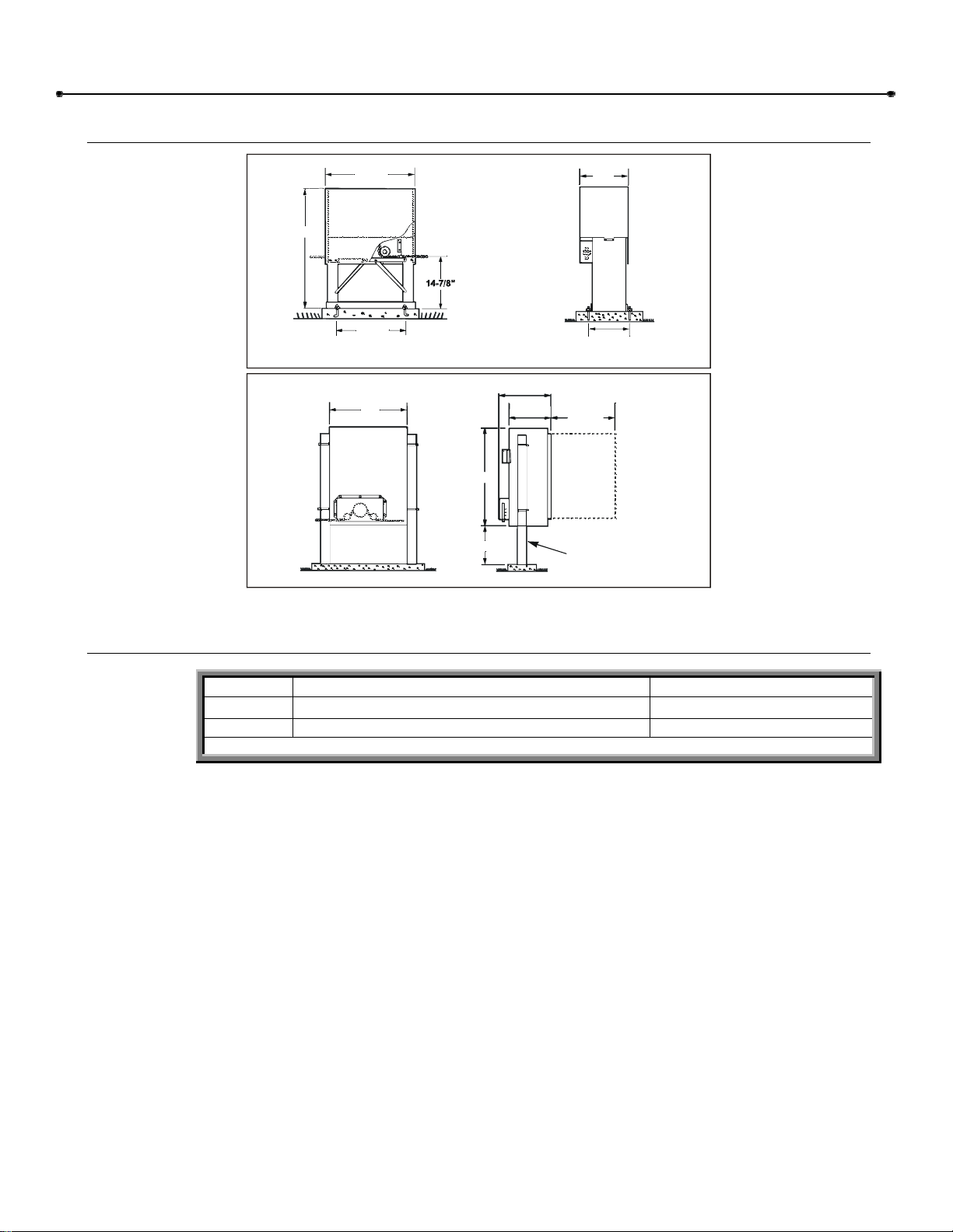
Operator Dimensions
MODEL SL580
25-7/8”
34-3/4”
21-1/8”
13”
10-7/8”
NOTE: Diagonal support braces shown are standard only on 1-1/2hp operators.
01-G0547F5
MODEL SL590
16-1/2”
13-1/2”
22-1/2”
ALLOW FOR
DOOR
OPENING
30”
12” MIN.
3” DIA. PIPE
(Not Supplied with Operator)
24”
Figure 1
Cycle Rates
MODEL APPLICATIONS
â CYCLE RATE PER HOUR
SL580 Heavy Duty, Industrial
20
SL590 Heavy Duty, Industrial with Harsh Environment
25
â Cycle = One full open and one full close.
Table 4
7 Safety Information
Doc 01-G0547
Rev D
Safety Information
Vehicular gate systems provide convenience and security. Gate systems are comprised of many
component parts. The gate operator is only one component. Each gate system is specifically
designed for an individual application.
Gate operating system designers, installers and users must take into account the possible hazards
associated with each individual application. Improperly designed, installed or maintained systems can
create risks for the user as well as the bystander. Gate systems design and installation must reduce
public exposure to potential hazards.
A gate operator can create high levels of force, in its function as a component part of a gate system.
Therefore, safety features must be incorporated into every design. Specific safety features include:
Gate Edges Enclosed Track Vertical Posts
Guards for exposed
rollers
Photo-electric Sensors Instructional and
Precautionary Signage
Screen Mesh
Important instructions follow. These instructions are intended to highlight certain safety related issues.
These instructions are not intended to be comprehensive. Because each application is unique, it is the
responsibility of the purchaser, designer, installer and end user to ensure that the total gate system is
safe for its intended use.
Safety Instructions
Select instructions are highlighted with this precautionary symbol (see left margin). Failure to follow
these selected instructions can result in serious injury or death.
STEP 1: BEFORE INSTALLATION
1 Confirm gate operator model is specified by Installation and Maintenance Manual for
application type, gate size and frequency or use.
2 Confirm ALL appropriate safety features, such as gate edges, photo-electric sensors,
vertical posts and enclosed tracks, are specified.
3 Confirm gate system design reduces pinch points and protects against entrapment.
4 Confirm gate system design has pedestrian access separate from vehicular entrance.
5 Confirm gate system design reduces traffic backup.
6 Confirm warning signage is included in design.
7 Confirm gate moves freely before installation of operator
8 Repair or service worn or damaged gate hardware before installation of operator.
9 To avoid installation hazards, review the gate system operation and installation
procedures, such as manual disconnect mechanism procedure.
10 Confirm control design prohibits unauthorized use.

8 Safety Information
Doc 01-G0547
Rev D
STEP 2: DURING INSTALLATION
1 Disconnect power at service panel before making any electrical connection.
2 Avoid pinch points, be aware of all moving parts.
3 Adjust clutch or load sensing device to minimum force setting.
4 Do not over-tighten cutch or adjust force setting above minimum.
5 Install controls where user cannot touch gate while operating controls.
6 Install controls where user has full view of gate operation.
7 Install two or more warning signs on the gate to alert persons in the area of automatic gate
operation. Warning signs must be conspicuous.
8 Install operator inside fence line. DO NOT install operator on public side of fence line.
9 Secure gate operator cover.
STEP 3: AFTER INSTALLATION
1 Test all safety features.
2 Train end user about basic functions and safety features of gate system.
3 Leave Installation and Maintenance Manual and Safety Instructions with end user.
Safety Information 9
Doc 01-G0547
Rev D
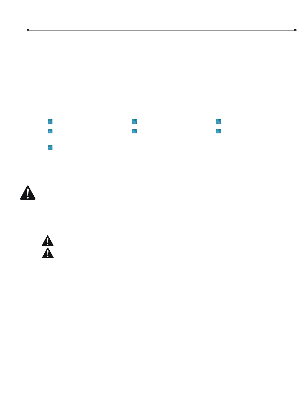
Safety Precautions for Open-Roller Gates and Ornamental “Grill
OPEN-ROLLER GATES
Injuries occur when people get their or feet caught between the top or bottom of the gate and the
gate roller. This potential pinch-point should be guarded against at all times. Enclosed style gate
tracks are available for refitting of these rollers from many fence suppliers. Also, roller guards are
available for installing over the rollers.
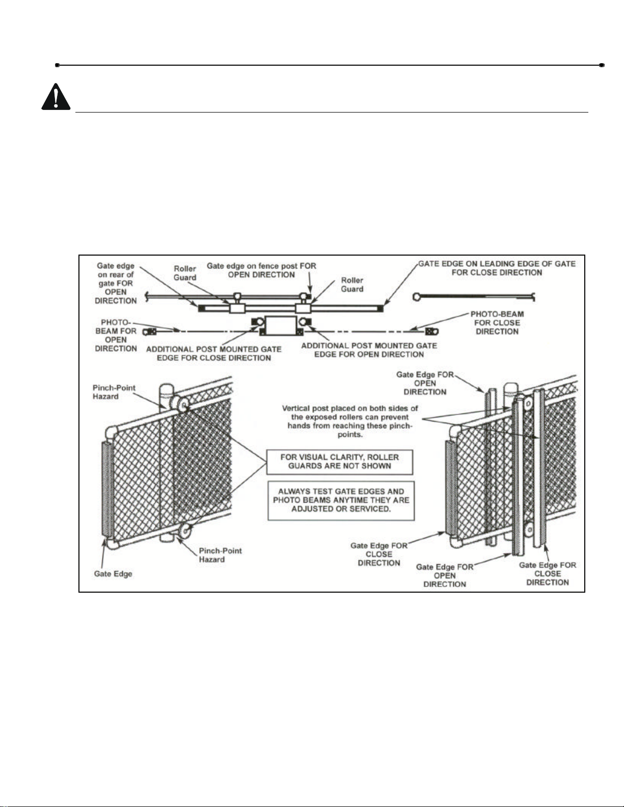
One more contact sensors shall be located at the leading edge, trailing edge, and post-mounted
both inside and outside of a vehicular horizontal slide gate.
Figure 2
10 Safety Information
Doc 01-G0547
Rev D
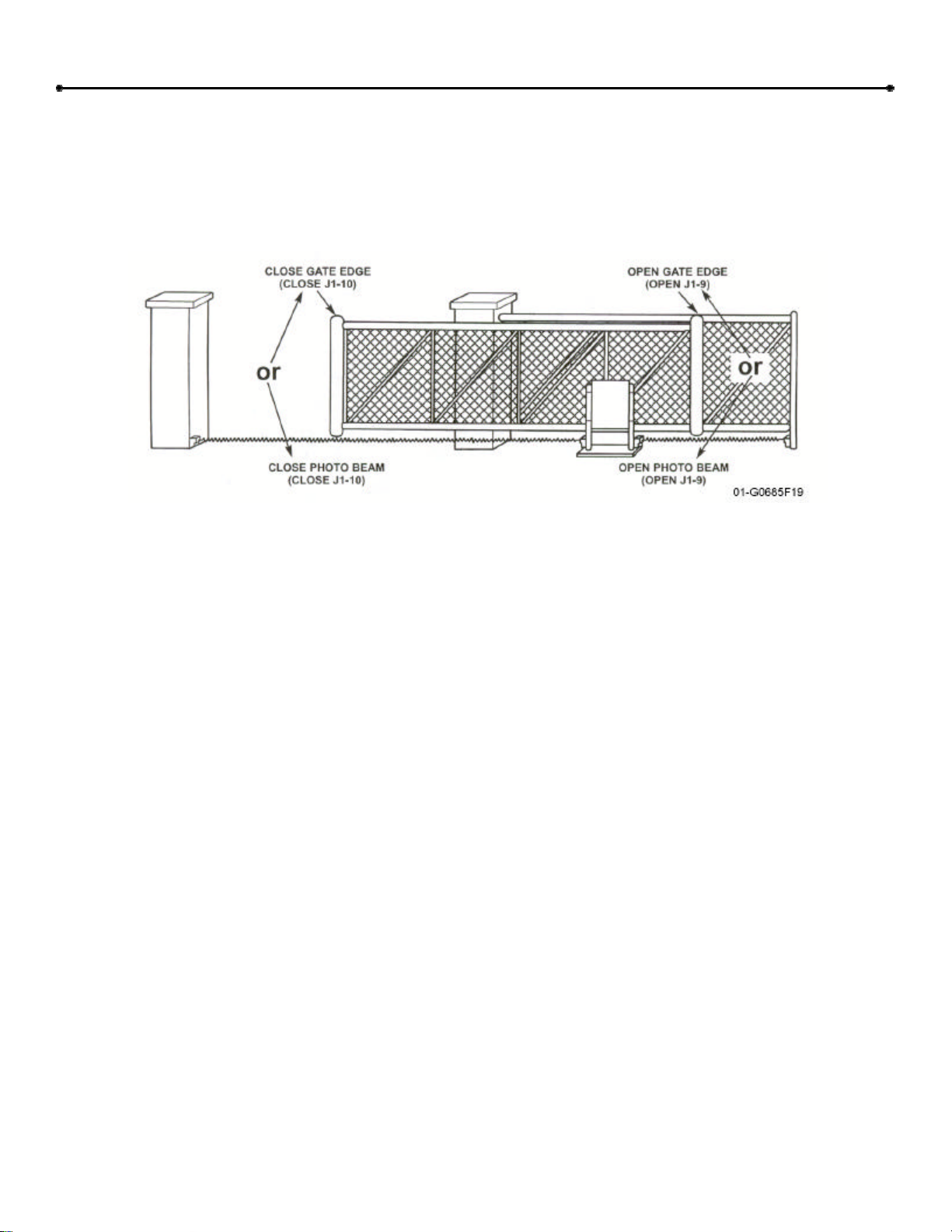
ORNAMENTAL “GRILL TYPE” GATES
Injuries occur when people put their hands and arms through openings in the grill and the gate is
operated. They cannot retract their arm and it gets caught between the moving gate grill and the
stationary fence post or fence. This potential hazard can be averted by placing a 4’ screen mesh
on the gate to prevent access through openings anywhere the gate may travel. See Safety
Brochure for details.
Figure 3
11 Pre-Installation Check-List
Doc 01-G0547
Rev D
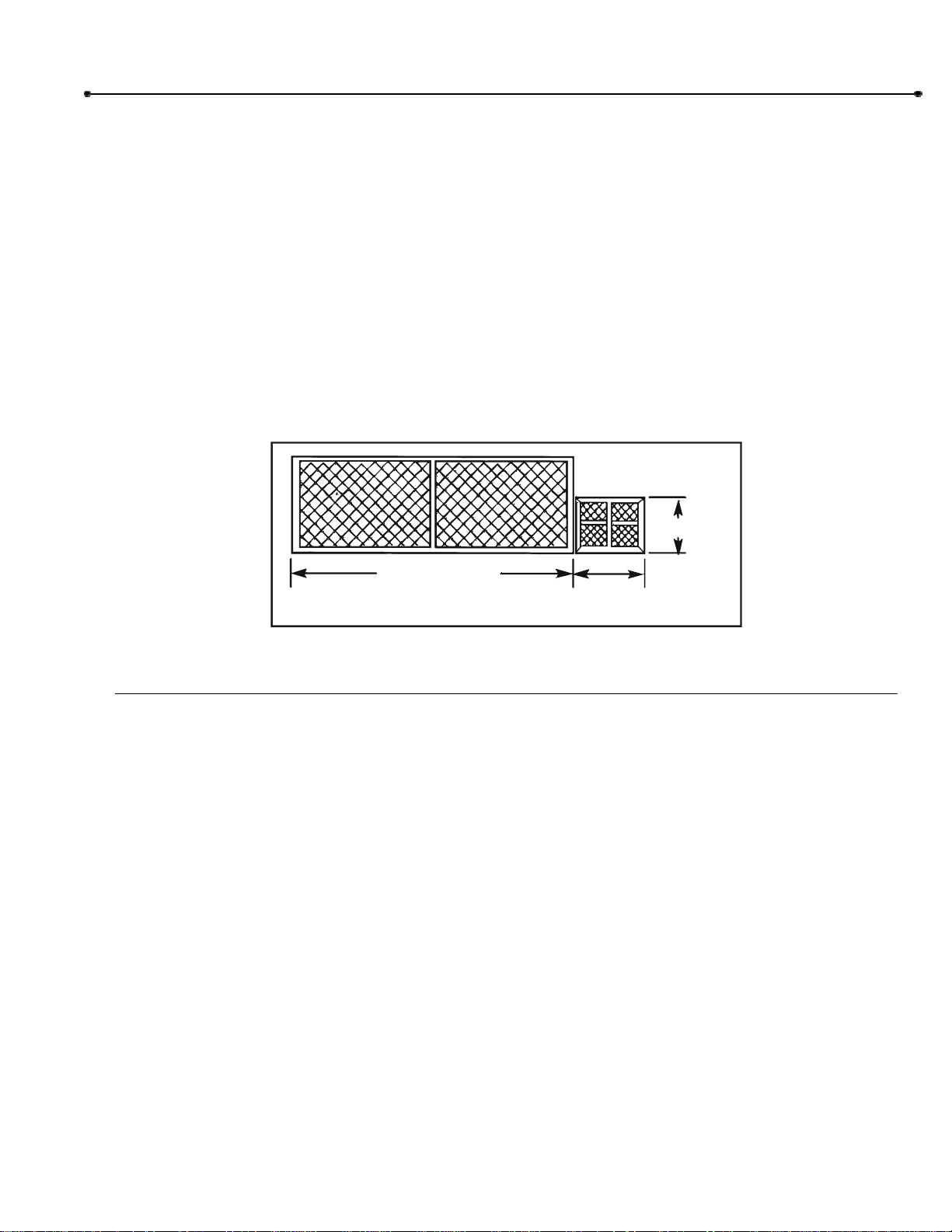
Pre-Installation Check-List
Φ Check the gate. It must operate smoothly and freely. If necessary, lubricate, adjust, or repair the
gate prior to operate installation. The gate must be level and plumb.
Φ Some gates may only be as wide as the gate opening. They may require a back frame to be
constructed to allow for chain attachments.
Φ Double check the size and weight of the gate to make sure that this operator is proper for this
application.
Φ If wiring has already been installed, check to make sure it meets the following specification and
requirements.
01-G0685F2
BACKFRAME
GATE OPENING
3 FT. MIN.
2 FT.
Figure 4
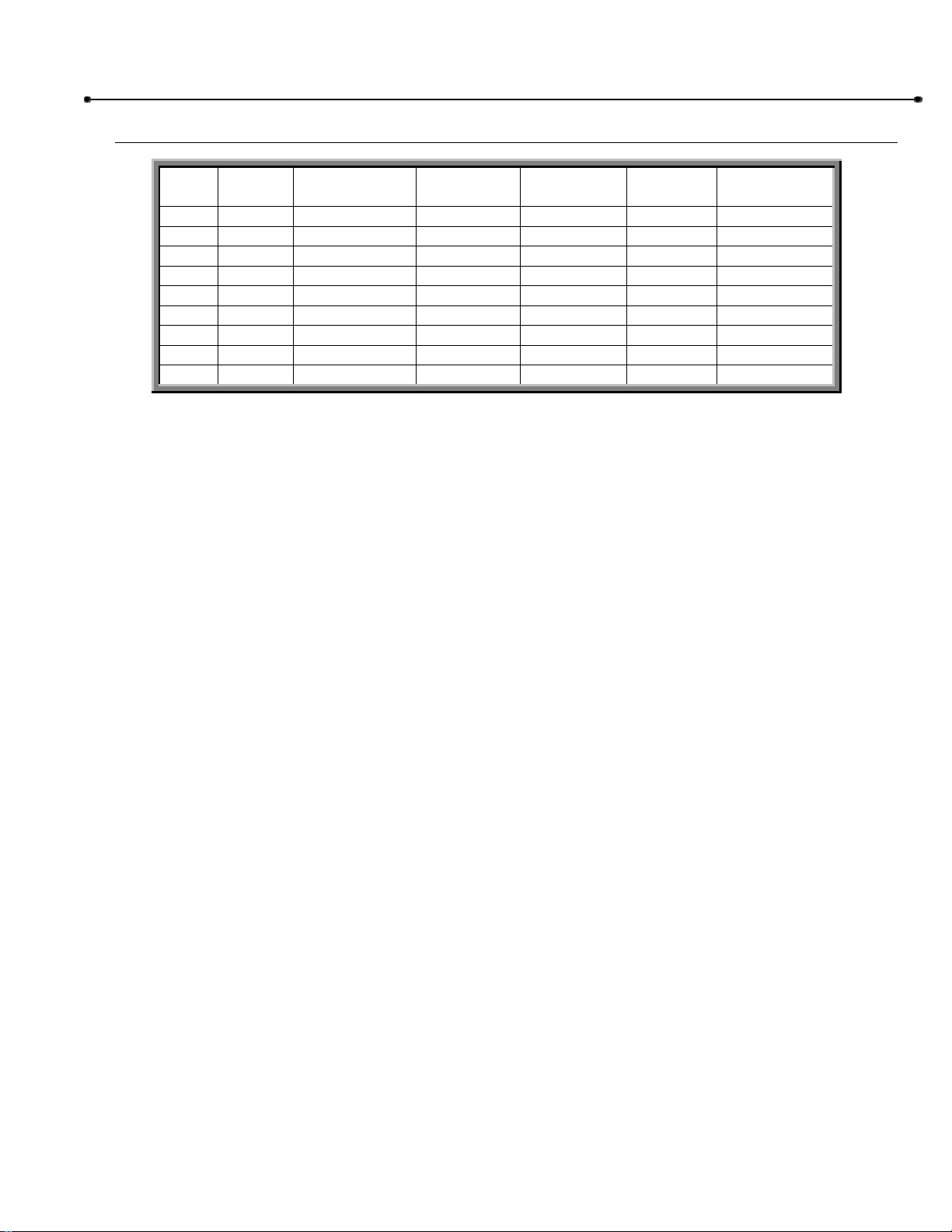
Wiring Specifications
Refer to Table 5.
A. The distances shown in Table 5 are measured in feet from the operator the power source.
B. These calculations are based on the National Electrical Code and allows for a 5% voltage
drop.
C. Supply voltage must be within 10% of the operator’s rating under load conditions.
D. There calculations are based on stranded copper wire.
E. It is highly recommended that only 90% of the distances shown be used; this will allow for a
10% safety factor.
F. For dual units, the distance shown should be cut in half.
G. Permanent wiring is to be employed as required by local codes.
H. All local codes must be strictly adhered to. It is very important that operator is properly
grounded.
I. Do not run control wires in the same conduit with power wires.
J. Do not run multi conductor or parallel conductor cable for controls.
K. All power wiring should be dedicated and protected.
12 Safety Information
Doc 01-G0547
Rev D
Single Phase 3 Phase
WIRE
GAUGE
HP 115 VAC 230 VAC 230 VAC 460 VAC 575 VAC
6
1/3
1/2
3/4
1
1-1/2
2
684
473
324
237
158
--
3,077
2,051
1,231
947
648
437
4,737
2,842
2,030
1,421
947
711
14,211
14,211
7,105
5,684
4,060
2,842
35,527
17,764
11,842
8,882
5,921
4,441
8
1/3
1/2
3/4
1
1-1/2
2
432
299
204
149
100
--
1,942
1,295
777
597
409
299
2,990
1,794
1,281
897
589
448
8,969
8,969
4,484
3,587
2,562
1,794
22,422
11,211
7,474
5,605
3,737
2,803
10
1/3
1/2
3/4
1
1-1/2
2
271
187
128
94
62
--
1,218
812,
487,
375,
256
187
1,876
1,125
804
563
375
281
5,627
5,627
2,814
2,251
1,608
1,125
14,068
7,034
4,689
3,517
2,345
1,758
12
1/3
1/2
3/4
1
1-1/2
2
170
117
80
59
39
--
763
509
305
235
161
117
1,175
705
503
352
235
175
3,524
3,524
1,762
1,410
1,007
705
8,810
4,405
2,937
2,203
1,468
1,101
Table 5
NOTE: Calculated using NEC guidelines. Local codes and conditions must be reviewed for suitability
of wire installation. Master/Slave units must be installed on separate circuits.
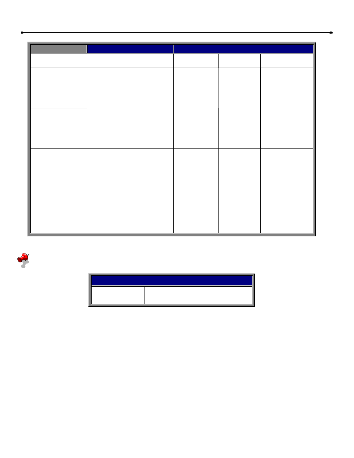
Control Wiring
Volt Max. Dist. (Ft.) Wire Gage
24 1000 18
Table 6
Loading...