


 Loading...
COMMERCIAL DC
VEHICULAR SLIDE GATE OPERATOR
INSTALLATION MANUAL
Model CSL24UL
THIS PRODUCT IS TO BE INSTALLED AND SERVICED BY A TRAINED GATE SYSTEMS TECHNICIAN ONLY.
This model is for use on vehicular passage gates ONLY and not intended for use on pedestrian passage gates.
This model is intended for use in Class I, II, III and IV vehicular slide gate applications.
Visit LiftMaster.com to locate a professional installing dealer in your area.
This gate operator is compatible with MyQ® and Security+ 2.0® accessories.
Access installation and technical support guides or register this product
1. Take a photo of the camera icon including the points ( ).
).
2. Send it in by texting the photo to 71403.
CSL24ULTECH

LiftMaster
300 Windsor Drive
Oak Brook, IL 60523

TABLE OF CONTENTS
SAFETY |
2 |
Safety Symbol and Signal Word Review................................................ |
2 |
Usage Class ........................................................................................... |
3 |
UL325 Entrapment Protection Requirements ........................................ |
3 |
Safety Installation Information............................................................... |
4 |
Gate Construction Information............................................................... |
5 |
INTRODUCTION |
6 |
Carton Inventory .................................................................................... |
6 |
Operator Specifications.......................................................................... |
7 |
Site Preparation ..................................................................................... |
8 |
INSTALLATION |
9 |
Types of Installations............................................................................. |
9 |
Step 1 Determine Location for Operator.............................................. |
10 |
Step 2 Install the Operator................................................................... |
11 |
Step 3 Attach the Chain ....................................................................... |
12 |
Step 4 Install Entrapment Protection ................................................... |
14 |
Step 5 Earth Ground Rod..................................................................... |
16 |
Step 6 Power Wiring............................................................................ |
16 |
Step 7 Connect Batteries ..................................................................... |
18 |
Step 8 Dual Gate Setup........................................................................ |
20 |
Step 9 Install the Cover ....................................................................... |
22 |
ADJUSTMENT |
23 |
Limit and Force Adjustment................................................................. |
23 |
Obstruction Test .................................................................................. |
24 |
PROGRAMMING |
25 |
Remote Controls (Not Provided) ......................................................... |
25 |
LiftMaster Internet Gateway (not provided) ......................................... |
26 |
Erase All Codes.................................................................................... |
26 |
Erase Limits ......................................................................................... |
26 |
Constant Pressure Override (CPO) ...................................................... |
26 |
Gate Hold Open Feature ....................................................................... |
26 |
To Remove and Erase Monitored |
|
Entrapment Protection Devices............................................................ |
26 |
OPERATION |
27 |
Gate Operator Setup Examples ............................................................ |
27 |
Control Board Overview ....................................................................... |
28 |
Manual Disconnect .............................................................................. |
29 |
Reset Switch........................................................................................ |
29 |
Operator Alarm .................................................................................... |
29 |
Remote Control.................................................................................... |
29 |
ACCESSORY WIRING |
30 |
External Control Devices...................................................................... |
30 |
Locks ................................................................................................... |
31 |
Miscellaneous Wiring........................................................................... |
31 |
EXPANSION BOARD |
32 |
Expansion Board Overview .................................................................. |
32 |
Auxiliary Relay 1 and 2 ........................................................................ |
33 |
Wiring Accessories to the Expansion Board ........................................ |
34 |
MAINTENANCE |
35 |
Important Safety Instructions .............................................................. |
35 |
Maintenance Chart ............................................................................... |
35 |
Batteries............................................................................................... |
36 |
Drive Train ........................................................................................... |
36 |
TROUBLESHOOTING |
37 |
Diagnostic Codes ................................................................................. |
37 |
Diagnostic Codes Table ....................................................................... |
38 |
Control Board LEDs ............................................................................. |
40 |
Troubleshooting Chart ......................................................................... |
41 |
APPENDIX |
44 |
Step 6 Solar Panel(s)........................................................................... |
44 |
SAMS Wiring With Relays Not Energized ............................................ |
48 |
Dual Gate Settings ............................................................................... |
48 |
Limit Setup With a Remote Control ..................................................... |
49 |
WIRING DIAGRAM |
50 |
REPAIR PARTS |
51 |
ACCESSORIES |
52 |
WARRANTY |
54 |
SAFETY
Safety Symbol and Signal Word Review
When you see these Safety Symbols and Signal Words on the following pages, they will alert you to the possibility of Serious Injury or Death if you do not comply with the warnings that accompany them. The hazard may come from something mechanical or from electric shock. Read the warnings carefully.
When you see this Signal Word on the following pages, it will alert you to the possibility of damage to your gate and/or the gate operator if you do not comply with the cautionary statements that accompany it. Read them carefully.
MECHANICAL
IMPORTANT NOTE: |
ELECTRICAL |
|||||
• |
BEFORE attempting to install, operate or maintain the operator, you must read and fully |
|
|
|
|
|
|
understand this manual and follow all safety instructions. |
|
|
|
|
|
|
|
|
|
|
|
|
• |
DO NOT attempt repair or service of your gate operator unless you are an Authorized |
|
|
|
|
|
|
|
|
|
|
||
|
Service Technician. |
|
|
|
|
|
WARNING: This product can expose you to chemicals including lead, which are known to the State of California to cause cancer or birth defects or other reproductive harm. For more information go to www.P65Warnings.ca.gov.
2
SAFETY
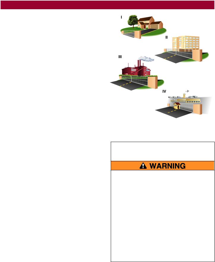
Usage Class
Class I - Residential Vehicular Gate Operator
A vehicular gate operator (or system) intended for use in garages or parking areas associated with a residence of one-to four single families.
Class II - Commercial/General Access Vehicular
Gate
A vehicular gate operator (or system) intended for use in a commercial location or building such as a multi-family housing unit (five or more single family units), hotel, garages, retail store, or other buildings accessible by or servicing the general public.
Class III - Industrial/Limited Access Vehicular
Gate
A vehicular gate operator (or system) intended for use in an industrial location or building such as a factory or loading dock area or other locations not accessible by or intended to service the general public.
Class IV - Restricted Access Vehicular Gate
Operator
A vehicular gate operator (or system) intended for use in a guarded industrial location or building such as an airport security area or other restricted access locations not servicing the general public, in which unauthorized access is prevented via supervision by security personnel.
UL325 Entrapment Protection Requirements
•A minimum of two independent* monitored entrapment protection devices are required to be installed at each entrapment zone
•Every installation is unique. It is the responsibility of the installer to install external monitored entrapment protection devices in each entrapment zone
•This vehicular slide gate operator will operate only after installation of a minimum of two independent* monitored entrapment protection devices in each direction; two in the open direction and two in the close direction.
•Entrapment protection device types include inherent (built into the operator), monitored external photoelectric sensors or monitored external edge sensors
•This operator is provided with an inherent entrapment protection device built into the operator that serves as one of the two independent devices
*Independent - the same type of device shall NOT be used for both entrapment protection devices.
IMPORTANT SAFETY
INSTRUCTIONS
To reduce the risk of INJURY or DEATH:
•READ AND FOLLOW ALL INSTRUCTIONS.
•NEVER let children operate or play with gate controls. Keep the remote control away from children.
•ALWAYS keep people and objects away from the gate. NO ONE SHOULD CROSS THE PATH OF THE MOVING GATE.
•Test the gate operator monthly. The gate MUST reverse on contact with an object or reverse when an object activates the noncontact sensors. After adjusting the force or the limit of travel, retest the gate operator. Failure to adjust and retest the gate operator properly can increase the risk of INJURY or DEATH.
•Use the emergency release ONLY when the gate is not moving.
•KEEP GATES PROPERLY MAINTAINED. Read the owner’s manual. Have a qualified service person make repairs to gate hardware.
•The entrance is for vehicles ONLY. Pedestrians MUST use separate entrance.
•SAVE THESE
INSTRUCTIONS.
3

SAFETY
Safety Installation Information
1.Vehicular gate systems provide convenience and security. Gate systems are comprised of many component parts. The gate operator is only one component. Each gate system is specifically designed for an individual application.
2.Gate operating system designers, installers and users must take into account the possible hazards associated with each individual application. Improperly designed, installed or maintained systems can create risks for the user as well as the bystander. Gate systems design and installation must reduce public exposure to potential hazards.
3.A gate operator can create high levels of force in its function as a component part of a gate system. Therefore, safety features must be incorporated into every design. Specific safety features include:
•Edges Sensors (contact)
•Guards for Exposed Rollers
•Photoelectric Sensors
•Screen Mesh
•Vertical Posts
•Instructional and Precautionary Signage
4.Install the gate operator only when:
a.The operator is appropriate for the construction and the usage class of the gate.
b.All openings of a horizontal slide gate are guarded or screened from the bottom of the gate to a minimum of 6 feet (1.8 m) above the ground to prevent a 2-1/4 inches (6 cm) diameter sphere from passing through the openings anywhere in the gate, and in that portion of the adjacent fence that the gate covers in the open position.
c.All exposed pinch points are eliminated or guarded, and guarding is supplied for exposed rollers.
5.The operator is intended for installation only on gates used for vehicles. Pedestrians must be supplied with a separate access opening. The pedestrian access opening shall be designed to promote pedestrian usage. Locate the gate such that persons will not come in contact with the vehicular gate during the entire path of travel of the vehicular gate.
6.The gate must be installed in a location so that enough clearance is supplied between the gate and adjacent structures when opening and closing to reduce the risk of entrapment.
7.The gate must be properly installed and work freely in both directions prior to the installation of the gate operator.
8.Permanently mounted access controls intended for users to activate, must be located at least 6 feet (1.8 m) away from any moving part of the gate and where the user is prevented from reaching over, under, around or through the gate to operate the controls. Outdoor or easily accessible controls shall have a security feature to prevent unauthorized use. Exception: Emergency access controls only accessible by authorized personnel (e.g. fire, police) may be placed at any location in the line-of-sight of the gate.
9.The Stop and/or Reset (if provided separately) must be located in the line-of-sight of the gate. Activation of the reset control shall not cause the operator to start.
10.A minimum of two (2) WARNING SIGNS shall be installed in the area of the gate. Each placard is to be visible by persons located on the side of the gate on which the placard is installed.
11.For a gate operator utilizing a non-contact sensor:
a.Reference owner’s manual regarding placement of non-contact sensor for each type of application. See Install Entrapment Protection section.
b.Care shall be exercised to reduce the risk of nuisance tripping, such as when a vehicle trips the sensor while the gate is still moving.
c.One or more non-contact sensors shall be located where the risk of entrapment or obstruction exists, such as the perimeter reachable by a moving gate or barrier.
12.For a gate operator utilizing a contact sensor such as an edge sensor:
a.One or more contact sensors shall be located where the risk of entrapment or obstruction exists, such as at the leading edge, trailing edge and post mounted both inside and outside of a vehicular horizontal slide gate.
b.A hard wired contact sensor shall be located and its wiring arranged so the communication between the sensor and the gate operator is not subject to mechanical damage.
c.A wireless device such as one that transmits radio frequency (RF) signals to the gate operator for entrapment protection functions shall be located where the transmission of the signals are not obstructed or impeded by building structures, natural landscaping or similar obstruction. A wireless device shall function under the intended end-use conditions.
4

SAFETY
Gate Construction Information
Vehicular gates should be installed in accordance with ASTM F2200: Standard Specification for Automated Vehicular Gate Construction. For a copy, contact ASTM directly at 610-832-9585 or www.astm.org.
1.General Requirements
1.1Gates shall be constructed in accordance with the provisions given for the appropriate gate type listed, refer to ASTM F2200 for additional gate types.
1.2Gates shall be designed, constructed and installed to not fall over more than 45 degrees from the vertical plane, when a gate is detached from the supporting hardware.
1.3Gates shall have smooth bottom edges, with vertical bottom edged protrusions not exceeding 0.50 inches (12.7 mm) when other than the exceptions listed in ASTM F2200.
1.4The minimum height for barbed tape shall not be less than 8 feet (2.44 m) above grade and for barbed wire shall not be less than 6 feet (1.83 m) above grade.
1.5An existing gate latch shall be disabled when a manually operated gate is retrofitted with a powered gate operator.
1.6A gate latch shall not be installed on an automatically operated gate.
1.7Protrusions shall not be permitted on any gate, refer to ASTM F2200 for Exceptions.
1.8Gates shall be designed, constructed and installed such that their movement shall not be initiated by gravity when an automatic operator is disconnected, in accordance with the following.
1.8.1Vehicular horizontal slide gate. Shall not result in continuous, unimpeded movement in either lineal direction of its travel.
1.9For pedestrian access in the vicinity of an automated vehicular gate, a separate pedestrian gate shall be provided. The pedestrian gate shall be installed in a location such that a pedestrian shall not come in contact with a moving vehicular access gate. A pedestrian gate shall not be incorporated into an automated vehicular gate panel.
2.Specific Applications
2.1Any non-automated gate that is to be automated shall be upgraded to conform to the provisions of this specification.
2.2This specification shall not apply to gates generally used for pedestrian access and to vehicular gates not to be automated.
2.3When the gate operator requires replacement, the existing gate shall be upgraded to conform to the provisions of this specification.
2.4When the gate of an automated gate system requires replacement, the new gate shall conform to the provisions of this specification.
3.Vehicular Horizontal Slide Gates
3.1The following provisions shall apply to Class I, Class II and Class III vehicular horizontal slide gates:
3.1.1All weight bearing exposed rollers 8 feet (2.44 m), or less, above grade shall be guarded or covered.
3.1.2All openings shall be designed, guarded, or screened from the bottom of the gate to the top of the gate or a minimum of 6 ft. (1.83 m) above grade, whichever is less, to prevent a 2 1⁄4 in. (57 mm) diameter sphere from passing through the openings
anywhere in the gate, and in that portion of the adjacent fence that the gate covers in the open position. The gate panel shall include the entire section of the moving gate,including any back frame or counterbalance portion of the gate.
3.1.3A gap, measured in the horizontal plane parallel to the roadway, between a fixed stationary object nearest the roadway, (such as a gate support post) and the gate frame when the gate is in either the fully open position or the fully closed position, shall not exceed 2
1/4 inches (57 mm). Exception: All other fixed stationary objects greater than 16 in. (406 mm) from the gate frame shall not be required to comply with this section.
3.1.4Positive stops shall be required to limit travel to the designed fully open and fully closed positions. These stops shall be installed at either the top of the gate, or at the bottom of the gate where such stops shall horizontally or vertically project no more than is required to perform their intended function.
3.1.5All gates shall be designed with sufficient lateral stability to assure that the gate will enter a receiver guide, refer to ASTM F2200 for panel types.
3.2The following provisions shall apply to Class IV vehicular horizontal slide gates:
3.2.1All weight bearing exposed rollers 8 feet (2.44 m), or less, above grade shall be guarded or covered.
3.2.2Positive stops shall be required to limit travel to the designed fully open and fully closed positions. These stops shall be installed at either the top of the gate, or at the bottom of the gate where such stops shall horizontally or vertically project no more than is required to perform their intended function.
5
INTRODUCTION
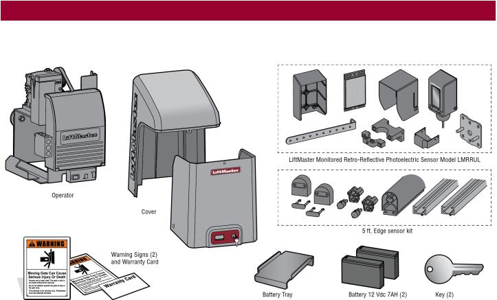
Carton Inventory
NOT SHOWN: Documentation Packet, Chain #41 - 30 feet, Eye Bolt Kit
6
INTRODUCTION
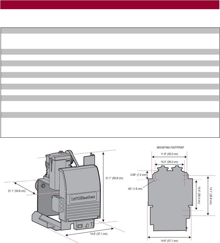
Operator Specifications
Usage Classification |
Class I, II, III, & IV |
Main AC Supply |
120 Vac, 4 Amps (10 Amps including Accessory Outlets) OR 240 Vac, 2 Amps |
|
When Optional Transformer Kit Model 3PHCONV is installed in the field, operator is rated |
|
208/240/480/575 VAC, 4.8/4.2/2.1/1.7 A, 60 Hz, 1 PH |
System Operating Voltage |
24 Vdc Transformer Run / Battery Backup |
Accessory Power |
24 Vdc, 500mA max. for ON + SW (switched) |
Solar Power Max |
24 Vdc at 60 watts max. |
Maximum Gate Weight |
1500 lbs. (680.4 kg) |
Minimum Gate Travel Distance |
4 feet (1.2 m) |
Maximum Gate Travel Distance |
50 feet (15.24 m) |
Maximum Gate Travel Speed |
1 foot/second |
Maximum Daily Cycle Rate |
Continuous |
Maximum Duty Cycle |
Continuous |
Operating Temperature |
Without Heater: -20°C to 60°C (-4°F to 140°F) |
|
With Optional Heater: -40°C to 60°C (-40°F to 140°F) |
Expansion Board
External Entrapment Protection Device Inputs (non-contact and/or contact)
Provided
Main board - up to 2 close entrapment protection devices and 1 open entrapment protection device.
Expansion board - up to 3 entrapment protection devices configurable to either close or open and up to 4 edge sensors using wireless edge sensor kit model LMWEKITU .
7

INTRODUCTION
Site Preparation
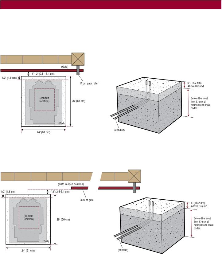
Check the national and local building codes BEFORE installation.
Conduit and Concrete Pad
Trench and install conduit. Before trenching, contact underground utility locating companies. Conduit must be UL approved for low and high voltage. Consider the operator placement BEFORE installing the pad or post.
Gate
Gate must be constructed and installed according to ASTM F2200 standards (refer to page 4). Gate must fit specifications of operator (refer to specifications).
Safety
Entrapment protection devices are required to protect against any entrapment or safety conditions encountered in your gate application. Install a warning sign (two provided) on the inside and outside of the property, where easily visible.
Additional Accessories
The vehicle loops allow the gate to stay open when vehicles are obstructing the gate path. Suggested for vehicles 14 feet (4.27 m) or longer. Vehicle loops are not required but are recommended. Before installing your Access Control Device(s) be sure to complete a site survey and determine the best device for your site needs.
8
INSTALLATION
•To AVOID damaging gas, power or other underground utility lines, contact underground utility locating companies BEFORE digging more than 18 inches (46 cm) deep.
•ALWAYS wear protective gloves and eye protection when changing the battery or working around the battery compartment.
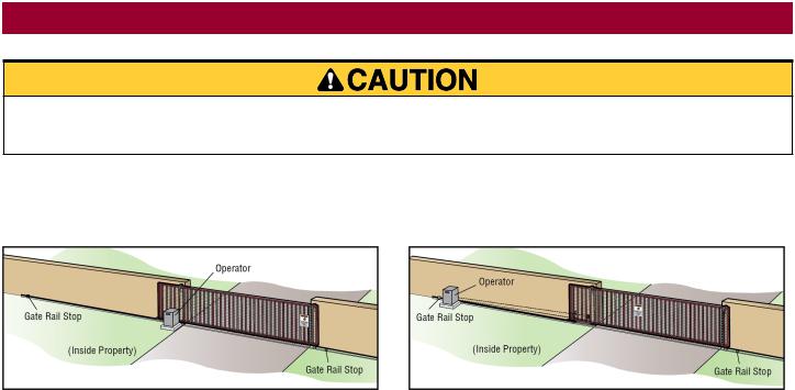
Types of Installations
Standard Installation |
Rear Installation |
9
INSTALLATION
Step 1 Determine Location for Operator
Check the national and local building codes before installation.
Standard Installation
1.The gate operator should be installed near the front roller of the gate. Lay out the concrete pad.
2.Install the electrical conduit.
3.Pour a concrete pad (reinforced concrete is recommended).
Rear Installation
1.The gate operator should be installed near the back of the gate in the OPEN position. Lay out the concrete pad.
2.Install the electrical conduit.
3.Pour a concrete pad (reinforced concrete is recommended).
10
INSTALLATION
Step 2 Install the Operator
Attach the operator to the concrete pad with appropriate fasteners. The gate operator should be installed near the front roller of the gate or near the back of the gate (in the OPEN position). The space between the gate and the output sprocket must be a minimum of 4 inches (10.2 cm). NOTE: An alternative to a concrete pad is to post mount the operator (refer to Accessories).
11
INSTALLATION
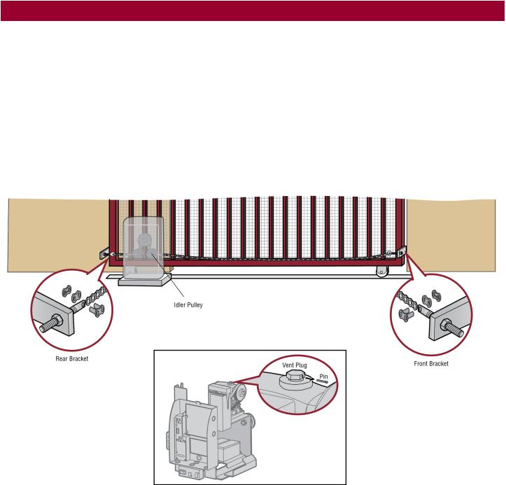
Step 3 Attach the Chain
Standard Installation
DO NOT run the operator until instructed.
1.Manually open the gate and line up the front bracket so the chain will be level with the idler pulley and parallel to the ground. Weld the front bracket in this position.
2.Manually close the gate and line up the rear bracket so the chain will be level with the idler pulley and parallel to the ground. Weld the rear bracket in this position.
3.Route the chain through the operator.
4.Connect the chain to the brackets using the eye bolt hardware. Chain should not be too tight or have excessive slack.
5.Remove the pin from the vent plug on the gear box.
NOTE: The chain should have no more than 1 inch (2.5 cm) of sag for every 10 feet (3 m) of chain length.
12
INSTALLATION
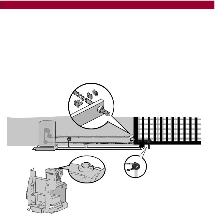
Rear Installation
DO NOT run the operator until instructed.
NOTE: This installation will require two extra idler pulleys. Make sure all exposed pinch points are guarded. Refer to Gate Construction Information on page 4.
1.Move the back pulley to the bottom hole in the operator.
2.Manually close the gate and align the bottom bracket so the chain will be level with the bottom idler pulley and parallel to the ground. Weld the bottom bracket in this position.
3.Align the top bracket so the chain will be level with the top idler pulley and parallel to the ground. Weld the upper bracket in this position.
4.Route the chain through the operator.
5.Connect the chain to the brackets using the eye bolt hardware. Chain should not be too tight or have excessive slack.
6.Remove the pin from the vent plug on the gear box.
NOTE: The chain should have no more than 1 inch (2.5 cm) of sag for every 10 feet (3 m) of chain length.
Vent Plug
Pin |
Idler Pulley MUST have |
|
safety cover. |
||
|
13
INSTALLATION
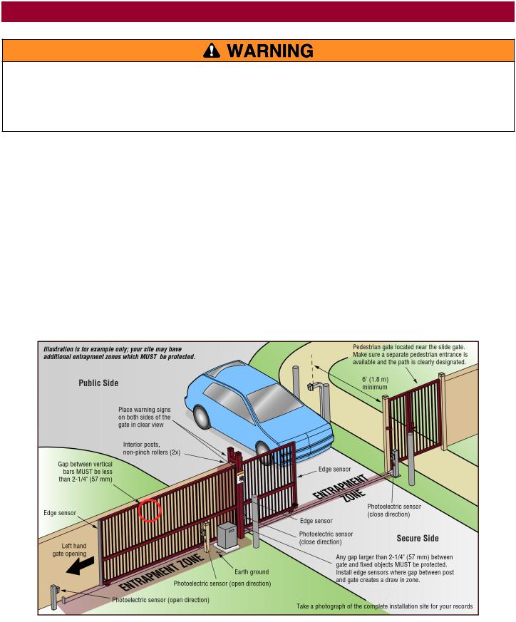
To prevent SERIOUS INJURY or DEATH from a moving gate:
•ALL gate operator systems REQUIRE two independent entrapment protection systems for each entrapment zone.
•Entrapment protection devices MUST be installed to protect anyone who may come near a moving gate.
•Locate entrapment protection devices to protect in BOTH the open and close gate cycles.
•Locate entrapment protection devices to protect between moving gate and RIGID objects, such as posts, walls, pillars, columns, or operator itself.
Step 4 Install Entrapment Protection
Entrapment protection MUST be installed according to the following UL 325 requirements:
•Slide gate operators require a minimum of two external monitored entrapment protection devices to function; one in the open direction and one in the close direction.
•Every installation is unique. It is the responsibility of the installer to ensure that ALL entrapment zones are protected with an external monitored entrapment protection device, protecting both the open and close gate cycles.
•LiftMaster monitored external entrapment protection devices MUST be used with LiftMaster operators to meet UL325 requirements, see Accessories.
•Test ALL entrapment protection devices after completing installation of the operator. For testing instructions, refer to the manual provided with your entrapment protection device.
Definitions
ENTRAPMENT: The condition when a person is caught or held in a position that increases the risk of injury.
SLIDE GATE ENTRAPMENT ZONE: An entrapment zone exists if at any point during travel, the gap between the gate and any opposing fixed edge or surface such as posts, walls, pillars, columns or operator itself, is less than 16" (406 mm) in a location up to 6 ft. (1.8 m) above grade.
Illustrations provided by DASMA Gate Systems Safety Guide
14
INSTALLATION
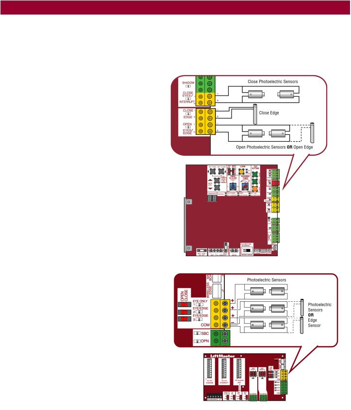
Wire Entrapment Protection Devices
There are three options for wiring the entrapment protection devices depending on the specific device and how the device will function. Refer to the specific entrapment protection device manual for more information. These entrapment protection device inputs are for monitored devices, which include pulsed photoelectric sensors, resistive edge sensors, and pulsed edge sensors. Only one monitored entrapment protection device may be wired to each input. Additional entrapment protection devices may be wired to the expansion board.
Control Board
CLOSES EYES/INTERRUPT
(2 Terminals) The CLOSE EYES/INTERRUPT input is for photoelectric sensor entrapment protection for the close direction. When an obstruction is sensed during gate closing the gate will open to the full open position and resets the Timer-to-Close. This input will be disregarded during gate opening.
CLOSE EDGE
(2 Terminals) The CLOSE EDGE input is for edge sensor entrapment protection for the close direction. When an obstruction is sensed during gate closing the gate will reverse to the full open position, disengaging the Timer-to-Close. This input will be disregarded during gate opening.
OPEN EYES/EDGE
(2 Terminals) The OPEN EYES/EDGE input is for photoelectric sensor or edge sensor entrapment protection for the open direction. When an obstruction is sensed during gate opening the gate will reverse for 4 seconds then stop. This input will be disregarded during gate closing.
Expansion Board
EYE ONLY and COM
Open or Close Direction Photoelectric Sensors, the functionality is based on the switch settings (located next to the terminals)
Switch set to CLOSE: gate reverses fully when an obstruction is sensed
Switch set to OPEN: gate reverses 4 seconds when an obstruction is sensed
EYE/EDGE and COM
Open or Close Direction Photoelectric Sensors or Edge Sensor, the functionality is based on the switch settings (located next to the terminals)
Switch set to CLOSE: gate reverses fully when an obstruction is sensed
Switch set to OPEN: gate reverses 4 seconds when an obstruction is sensed
15
INSTALLATION
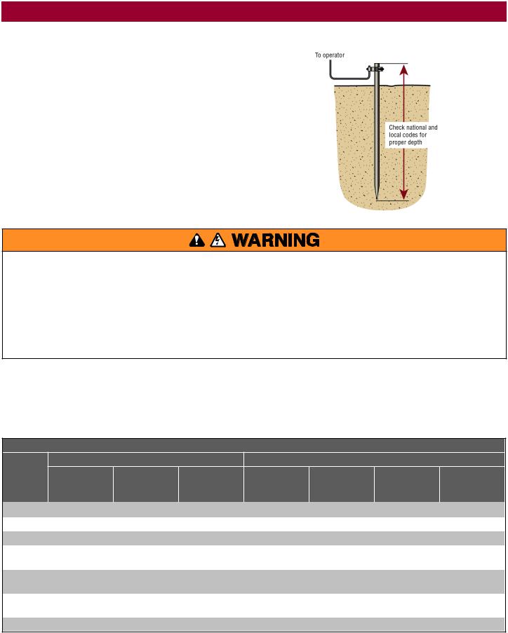
Step 5 Earth Ground Rod
Use the proper earth ground rod for your local area. The ground wire must be a single, whole piece of wire. Never splice two wires for the ground wire. If you should cut the ground wire too short, break it, or destroy its integrity, replace it with a single wire length.
1.Install the earth ground rod within 3 feet (.9 m) of the operator.
2.Run wire from the earth ground rod to the operator.
NOTE: If the operator is not grounded properly the range of the remote controls will be reduced and the operator will be more susceptible to lightning and surge damage.
Step 6 Power Wiring
To reduce the risk of SEVERE INJURY or DEATH:
•ANY maintenance to the operator or in the area near the operator MUST NOT be performed until disconnecting the electrical power (AC or solar and battery) and locking-out the power via the operator power switch. Upon completion of maintenance the area MUST be cleared and secured, at that time the unit may be returned to service.
•Disconnect power at the fuse box BEFORE proceeding. Operator MUST be properly grounded and connected in accordance with national and local electrical codes. NOTE: The operator should be on a separate fused line of adequate capacity.
•ALL electrical connections MUST be made by a qualified individual.
•DO NOT install ANY wiring or attempt to run the operator without consulting the wiring diagram.
•ALL power wiring should be on a dedicated circuit and well protected. The location of the power disconnect should be visible and clearly labeled.
•ALL power and control wiring MUST be run in separate conduit.
The operator can be wired for either 120 Vac or 240 Vac or a solar panel (not provided). Follow the directions according to your application. An optional Transformer Kit (Model 3PHCONV) can be used to change the input voltage (208/240/480/575 Vac) to an output voltage of 120 Vac (refer to Accessories). For dual gate applications, power will have to be connected to each operator. Main power supply and control wiring MUST be run in separate conduits.
SOLAR APPLICATIONS: For solar applications refer to Solar Panels section in the Appendix. Follow the directions according to your application.
NOTE: If using an external receiver use shielded wire for the connections and mount the receiver away from the operator to avoid interference from the operator.
MAXIMUM WIRE LENGTH
AMERICAN |
STANDARD OPERATOR |
OPERATOR + ACCESSORIES POWERED BY TRANSFORMER KIT |
|||||
|
|
|
|
|
|
|
|
WIRE |
120 VAC, 10A |
|
|
|
|
|
|
GAUGE |
(includes fully |
120 VAC, 4A |
240 VAC, 2A |
208 VAC, 4.8A |
240 VAC, 4.2A |
480 VAC, 2.1A |
575 VAC, 1.7A |
(AWG) |
loaded outlets) |
|
|
|
|
|
|
|
|
|
|
|
|
|
|
|
|
|
|
|
|
|
|
14 |
100 (30.5 m) |
250 (76.2 m) |
1,000 (304.8 m) |
360 (109.7 m) |
480 (146.3 m) |
1,900 (579.1 m) |
2,800 (853.4 m) |
|
|
|
|
|
|
|
|
12 |
160 (48.8 m) |
400 (121.9 m) |
1,600 (487.7 m) |
570 (173.7 m) |
750 (228.6 m) |
3,000 (914.4 m) |
4,500 (1,371.6 m) |
|
|
|
|
|
|
|
|
10 |
250 (76.2 m) |
630 (192 m) |
2,500 (762 m) |
900 (274.3 m) |
1,200 (365.8 m) |
4,800 (1,463 m) |
7,100 (2,164.1 m) |
|
|
|
|
|
|
|
|
8 |
400 (121.9 m) |
1,000 (304.8 m) |
4,000 |
1,400 (426.7 m) |
1,900 (579.1 m) |
7,600 |
11,300 |
|
|
|
(1,219.2 m) |
|
|
(2,316.5 m) |
(3,444.2 m) |
|
|
|
|
|
|
|
|
6 |
636 (193.9 m) |
1,600 (487.7 m) |
6,400 (1950.7 m) |
2,300 (701 m) |
3,000 (914.4 m) |
12,100 |
18,000 |
|
|
|
|
|
|
(3,688.1 m) |
(5,486.4 m) |
|
|
|
|
|
|
|
|
4 |
1,000 (304.8 m) |
2,500 (762 m) |
10,100 |
3,700 |
4,800 (1,463 m) |
19,300 |
28,500 |
|
|
|
(3,078.5 m) |
(1,127.8 m) |
|
(5,882.6 m) |
(8,686.8 m) |
|
|
|
|
|
|
|
|
Chart assumes: copper wire, 65°C, 5% drop
16
INSTALLATION
All control wiring used to connect external devices to Class 2 circuits of the operator must be (QPTZ) Power-Limited Circuit Cables, Type CL2, CL2P, CL2R, or CL2X or other cable with equivalent or better electrical, mechanical, and flammability ratings.
240 VAC only
The accessory outlet is disabled and cannot be used with the 240 Vac option.
1.Remove the outlet housing from the electrical box by removing the screws (2).
2.Pull the outlet housing out and locate the power wiring connector on the EMI board.
3.Unplug the power wiring connector from the 120 Vac socket (factory default location) and plug it into the 240 Vac socket.
4.Replace the outlet housing by securing with the screws. The operator is now set for 240 Vac operation.
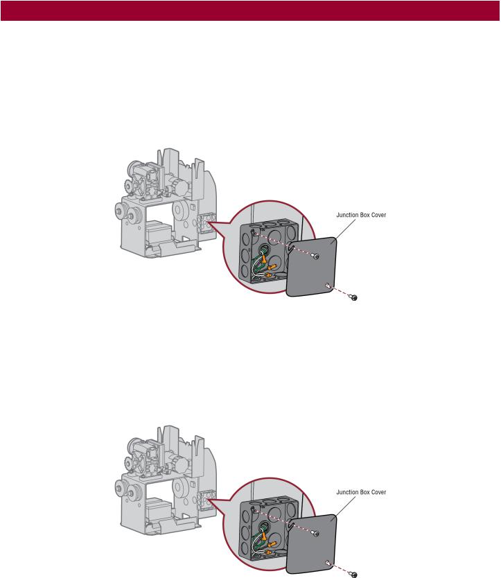
120 VAC and 240 VAC
1.Turn off the AC power from the main power source circuit breaker.
2.Run the AC power wires to the operator.
3.Remove the junction box cover.
4.Connect the green wire to the earth ground rod and AC ground using a wire nut. NOTE: The earth ground rod can be grounded to the chassis.
5.Connect the white wire to NEUTRAL using a wire nut.
6.Connect the black wire to HOT using a wire nut.
7.Replace the junction box cover. Ensure the wires are not pinched.
17
Loading...