


UT8 and RT8
Exercise Bikes
U S E R M A N U A L
CORPORATE HEADQUARTERS
10601 West Belmont Avenue
Franklin Park, Illinois 60131 • U.S.A. 847.288.3300 • FAX: 847.288.3703 800.735.3867 (Toll-free within U.S.A., Canada)
www.lifefitness.com
INTERNATIONAL OFFICES
LIFE FITNESS ASIA PACIFIC LTD
Room 2610, Miramar Tower 132 Nathan Road Tsimshatsui, Kowloon HONG KONG
Telephone: (+852) 2891.6677 FAX: (+852) 2575.6001
LIFE FITNESS ATLANTIC BV LIFE FITNESS BENELUX
Bijdorpplein 25-31 2992 LB Barendrecht THE NETHERLANDS
Telephone: (+31) 180.646.666 FAX: (+31) 180.646.699 Telephone: (+32) 87.300.942 FAX: (+32) 87.300.943
LIFE FITNESS DO BRAZIL
Av. Dr. Dib Sauaia Neto 1478 Alphaville, Barueri, SP 06465-140
BRAZIL
Telephone (+55) 11.4193.8282 FAX: (+55) 11.4193.8283
LIFE FITNESS VERTRIEBS GMBH
Dückegasse 7-9/3/36 1220 Vienna AUSTRIA
Telephone: (+43) 1.61 57 198 FAX: (+43) 1.61 57 198.20
LIFE FITNESS IBERIA
Pol. Ind. Molí dels Frares. c/C, nº 12 08620 Sant Vicenç dels Horts (Barcelona) SPAIN
Telephone: (+34) 93.672.4660 FAX: (+34) 93.672.4670
LIFE FITNESS EUROPE GMBH
Siemensstrasse 3 85716 Unterschleissheim GERMANY
Telephone: (+49) 89.31 77 51.0 FAX: (+49) 89.31 77 51.99
LIFE FITNESS ITALIA S.R.L.
Via Vittorio Veneto, 57/A 39042 Bressanone (Bolzano) ITALY
Telephone: (+39) 0472.835 470 FAX: (+39) 0472.833 150
LIFE FITNESS LATIN AMERICA and CARIBBEAN
10601 West Belmont Avenue Franklin Park, Illinois 60131 U.S.A.
Telephone: (+1) 847.288.3300 FAX:(+1) 847.288.3886
LIFE FITNESS UK LTD
Queen Adelaide
Ely, Cambs CB7 4UB UNITED KINGDOM Telephone: (+44) 1353.666017 FAX: (+44) 1353.666018
LIFE FITNESS JAPAN
Nippon Brunswick Bldg., #8F 5-27-7 Sendagaya Shibuya-Ku, Tokyo
JAPAN 151-0051
Telephone: (+81) 3.3359.4309 FAX: (+81) 3.3359.4307
M051-00K63-A011 9/02
1

Before using this product, it is essential to read this ENTIRE operation manual and ALL installation instructions.
This will help in setting up the equipment quickly
and in instructing others on how to use it correctly and safely.
FCC Warning - Possible Radio / Television Interference
NOTE: This equipment has been tested and found to comply with the limits for a Class B digital device, pursuant to part 15 of the FCC rules. These limits are designed to provide reasonable protection against harmful interference in a residential installation. This equipment generates, uses and can radiate radio frequency energy, and if not installed and used in accordance with the operation manual, may cause harmful interference to radio communications. However, there is no guarantee that the interference will not occur in a particular installation. If this equipment does cause harmful interference to radio or television reception, which can be determined by turning the equipment off and on, the user is encouraged to try to correct the interference by one or more of the following measures:
Reorient or relocate the receiving antenna.
Increase the separation between the equipment and the receiver.
Connect the equipment into an outlet on a circuit different from that to which the receiver is connected.
Consult the dealer or an experienced radio/TV technician for help.
Class HB (Home): Domestic use. Not suitable for therapeutic purposes.
CAUTION: Any changes or modifications to this equipment could void the product warranty.
Any service, other than cleaning or user maintenance, must be performed by an authorized service representative. There are no user-serviceable parts.
2
TABLE OF CONTENTS
Unpacking and Assembly . . . . . . . . . . . . . . . . . . . . . . . . . . . . . . . . . . . . . . . . . . . . . . . . . . . . . . . . . . . . . . . . . . . .4
Operation . . . . . . . . . . . . . . . . . . . . . . . . . . . . . . . . . . . . . . . . . . . . . . . . . . . . . . . . . . . . . . . . . . . . . . . . . . . . . . . . .8
1. |
Getting Started . . . . . . . . . . . . . . . . . . . . . . . . . . . . . . . . . . . . . . . . . . . . . . |
. . . . . . . . . . . . . . . . . . . . . . .9 |
1.1 |
Important Safety Instructions . . . . . . . . . . . . . . . . . . . . . . . . . . . . . . . . . . . |
. . . . . . . . . . . . . . . . . . . . . . .9 |
1.2 |
Set-up . . . . . . . . . . . . . . . . . . . . . . . . . . . . . . . . . . . . . . . . . . . . . . . . . . . |
. . . . . . . . . . . . . . . . . . . . . . .10 |
|
Where to place the Exercise Bike // How to stabilize the Exercise Bike |
// How to Adjust the Seat // |
|
How to Adjust the Pedal Straps // Starting Up the Bike |
|
2. |
The Display Console . . . . . . . . . . . . . . . . . . . . . . . . . . . . . . . . . . . . . . . . . |
. . . . . . . . . . . . . . . . . . . . . . .12 |
2.1 |
The Display Console Overview . . . . . . . . . . . . . . . . . . . . . . . . . . . . . . . . . |
. . . . . . . . . . . . . . . . . . . . . . .12 |
2.2 |
Display Console Descriptions . . . . . . . . . . . . . . . . . . . . . . . . . . . . . . . . . . |
. . . . . . . . . . . . . . . . . . . . . . .13 |
2.3 |
The Accessory Tray and Reading Rack . . . . . . . . . . . . . . . . . . . . . . . . . . . |
. . . . . . . . . . . . . . . . . . . . . . .14 |
3. |
Heart Rate Zone Training Exercise . . . . . . . . . . . . . . . . . . . . . . . . . . . . . . |
. . . . . . . . . . . . . . . . . . . . . . .15 |
3.1 |
Why Heart Rate Zone Training Exercise? . . . . . . . . . . . . . . . . . . . . . . . . . |
. . . . . . . . . . . . . . . . . . . . . . .15 |
3.2 |
Heart Rate Monitoring . . . . . . . . . . . . . . . . . . . . . . . . . . . . . . . . . . . . . . . . |
. . . . . . . . . . . . . . . . . . . . . . .16 |
|
The Hand Pulse Sensor System // The Telemetry Heart Rate Chest Strap |
|
4. |
The Workouts . . . . . . . . . . . . . . . . . . . . . . . . . . . . . . . . . . . . . . . . . . . . . . |
. . . . . . . . . . . . . . . . . . . . . . .18 |
4.1 |
Workout Overviews . . . . . . . . . . . . . . . . . . . . . . . . . . . . . . . . . . . . . . . . . . |
. . . . . . . . . . . . . . . . . . . . . . .18 |
4.2 |
Using the Workouts . . . . . . . . . . . . . . . . . . . . . . . . . . . . . . . . . . . . . . . . . . |
. . . . . . . . . . . . . . . . . . . . . . .18 |
|
To Begin any Workout // Selecting Quick Start // Selecting a Workout // Entering a Duration // |
|
|
Entering Age // Selecting the Difficulty Level or Target Heart Rate // Pausing Workouts // |
|
|
Ending Workouts Early // Exercise Bike Workout Setup Steps (chart) |
|
4.3 |
Workout Descriptions . . . . . . . . . . . . . . . . . . . . . . . . . . . . . . . . . . . . . . . . |
. . . . . . . . . . . . . . . . . . . . . . .20 |
|
Quick Start // Hill // Random // Manual // Outdoor Training // Gradual Hill // Fat Burner // |
|
|
Cardio // Cardio Hill // Cardio Interval // Cardio Endurance Workout |
|
4.4 |
My WorkoutsTM Personal Programs . . . . . . . . . . . . . . . . . . . . . . . . . . . . . . |
. . . . . . . . . . . . . . . . . . . . . . .25 |
|
Using a Workout Saved Under My Workouts // Editing Workouts and Viewing Statistics |
|
5. |
Optional Settings . . . . . . . . . . . . . . . . . . . . . . . . . . . . . . . . . . . . . . . . . . . |
. . . . . . . . . . . . . . . . . . . . . . .26 |
5.1 |
Entering and Using the Optional Settings Feature . . . . . . . . . . . . . . . . . . . |
. . . . . . . . . . . . . . . . . . . . . . .26 |
6. |
Service and Technical Data . . . . . . . . . . . . . . . . . . . . . . . . . . . . . . . . . . . . |
. . . . . . . . . . . . . . . . . . . . . . .27 |
6.1 |
Preventative Maintenance Tips . . . . . . . . . . . . . . . . . . . . . . . . . . . . . . . . . |
. . . . . . . . . . . . . . . . . . . . . . .27 |
6.2 |
Preventative Maintenance Schedule . . . . . . . . . . . . . . . . . . . . . . . . . . . . . |
. . . . . . . . . . . . . . . . . . . . . . .27 |
6.3 |
Troubleshooting the Telemetry Heart Rate Chest Strap . . . . . . . . . . . . . . . |
. . . . . . . . . . . . . . . . . . . . . . .28 |
|
Heart Rate Reading is Erratic or Absent Entirely // Heart Rate Reading is Erratic or Extremely High |
|
6.4 |
Troubleshooting the Handpulse Sensors . . . . . . . . . . . . . . . . . . . . . . . . . . |
. . . . . . . . . . . . . . . . . . . . . . .28 |
6.5 |
How to Obtain Product Service . . . . . . . . . . . . . . . . . . . . . . . . . . . . . . . . . |
. . . . . . . . . . . . . . . . . . . . . . .29 |
7. |
Specifications . . . . . . . . . . . . . . . . . . . . . . . . . . . . . . . . . . . . . . . . . . . . . . |
. . . . . . . . . . . . . . . . . . . . . . .30 |
7.1 |
Upright Exercise Bike Specifications . . . . . . . . . . . . . . . . . . . . . . . . . . . . . |
. . . . . . . . . . . . . . . . . . . . . . .30 |
7.2 |
Recumbent Exercise Bike Specifications . . . . . . . . . . . . . . . . . . . . . . . . . . |
. . . . . . . . . . . . . . . . . . . . . . .31 |
© 2002 Life Fitness, a division of Brunswick Corporation. All rights reserved. Life Fitness and Heart Rate Zone Training are registered trademarks of Brunswick Corporation. Essential, My Workouts, and Sport are a trademarks of the Brunswick Corporation. Any use of these trademarks, without the express written consent of Life Fitness is forbidden.
3
UNPACKING THE UPRIGHT EXERCISE BIKE
1.Carefully cut and remove the SHIPPING BANDS.
2.Carefully cut the tape securing the TOP FLAPS.
3.Fold the TOP FLAPS outward fully.
4.With the help of another person, remove the TOP SHIPPING TRAY.
CAUTION: Some parts extend through the bottom of the SHIPPING TRAY. Be careful not to damage the parts when lifting the TOP SHIPPING TRAY from the SHIPPING CARTON.
5.Remove the DISPLAY CONSOLE carton and the HANDLEBAR ASSEMBLY from beside the BASE UNIT.
6.With the help of another person, lift the BASE UNIT from the SHIPPING CARTON. Remove the protective packaging from the unit.
4
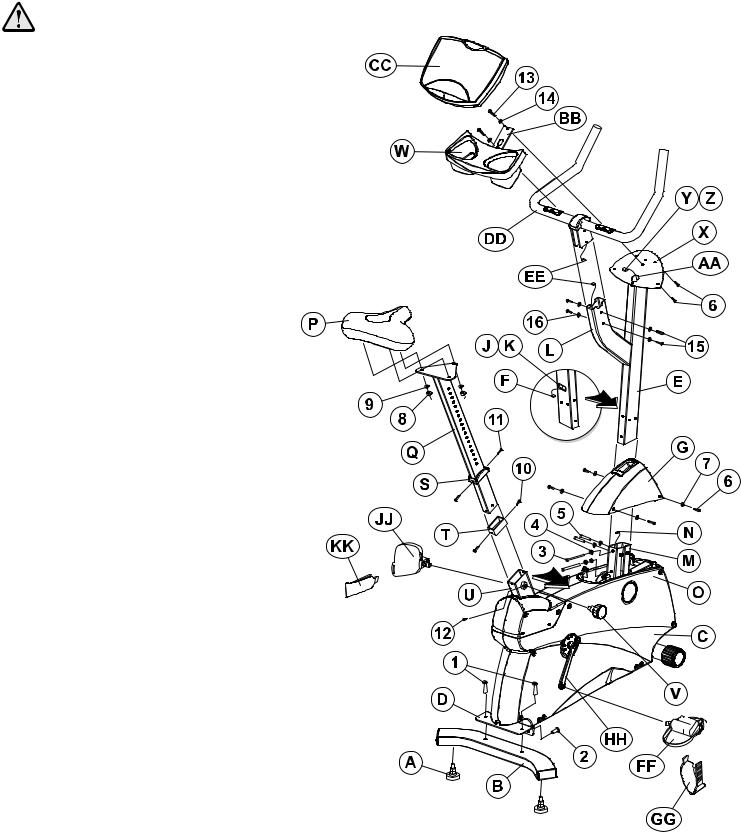
ASSEMBLING THE
UPRIGHT EXERCISE BIKE
Tools Required: Metric Wrench Set, Metric Allen
Wrench Set, Phillips Screwdriver
1.Locate and install the two LEVELER FEET (A) to the bottom of the REAR STABILIZER (B).
2.With the bends facing rearward, attach the REAR STABILIZER
(B)to the BASE UNIT (C) using two 2-3/8" BUTTON HEAD SCREWS (1) from the top of the REAR STABILIZER BRACKET
(D)and two 13/16" BUTTON HEAD SCREWS (2) from the front side of the REAR STABILIZER BRACKET. Tighten the SCREWS securely.
3.Locate the MONOCOLUMN (E). Cut the WIRE TIE securing the WIRE (F) to the bottom of the MONOCOLUMN. Slide the MONOCOLUMN COVER (G) onto the MONOCOLUMN (E) as shown. Slide the MONOCOLUMN COVER up to the HANDLEBAR TUBE (H).
5.Locate and insert the GROMMET (J) into the SIDE ACCESS HOLE (K) of the MONOCOLUMN (E). Pull the WIRE (F) out through the SIDE ACCESS HOLE.
6.With the HANDLEBAR TUBE (L) facing the rear of the unit as shown, slide the MONOCOLUMN (E) into the MONOCOLUMN BRACKET (M) of the BASE UNIT (C) . Slide the MONOCOLUMN down until it is fully seated. Secure the MONOCOLUMN to the MONOCOLUMN BRACKET using two 3-15/16" HEX HEAD BOLTS (3) and three THICK FLAT WASHERS (4) (as shown) from the rear side of the MONOCOLUMN and two 2-3/8" HEX HEAD BOLTS (5) and THICK FLAT WASHERS (4) from the user left side of the MONOCOLUMN BRACKET. Tighten the BOLTS securely.
CAUTION: Be careful not to pinch the WIRE(S) (N) leading from the MONOCOLUMN BRACKET (M) when inserting the MONOCOLUMN (E) into the MONOCOLUMN BRACKET.
7.Connect the WIRE(s) (N) leading from the MONOCOLUMN BRACKET (M) to the corresponding WIRE (F) from the SIDE ACCESS HOLE (K) of the MONOCOLUMN (E). Slide the MONOCOLUMN COVER (G) downward to the meet the MAIN SHROUDS (O). Secure the MONOCOLUMN COVER to the MAIN SHROUDS using four 1/2" PHILLIPS SCREWS (6) and matching FLAT WASHERS (7). Tighten the SCREWS securely. Do not overtighten the SCREWS.
8.Locate the SEAT (P) and SEAT POST (Q). Remove the three NYLOCK NUTS (8) and FLAT WASHERS (9) from the threaded studs on the bottom of the SEAT. Align the three threaded studs of the SEAT with the mounting holes in the SEAT POST MOUNTING PLATE (R). Secure the SEAT to the SEAT POST MOUNTING PLATE using the three previously removed NYLOCK NUTS and FLAT WASHERS. Tighten the NUTS securely.
9.Locate the SEAT POST CAP (S). With the curved side facing upward toward the SEAT (P) and the inside notch aligned with the SEAT POST ADJUSTMENT DECAL, slide the SEAT POST CAP over the SEAT POST (Q).
10.Locate and slide the SEAT POST SPACER (T) over the end of the SEAT POST (Q). Using two 1/4" PHILLIPS SCREWS (10), secure the SEAT POST SPACER to the end of the SEAT POST. Tighten the SCREWS securely.
11.With the nose of the SEAT (P) facing forward, insert the SEAT POST (Q) into the SEAT POST SUPPORT (U).
12.Slide the SEAT POST CAP (S) downward to meet the top of the SEAT POST SUPPORT (U). Secure the SEAT POST CAP to the SEAT POST SUPPORT using two 1/4" PHILLIPS SCREWS (11). Tighten the SCREWS securely. Do not overtighten the SCREWS.
13.Begin inserting the SEAT ADJUSTMENT KNOB (V). Lift upward on the SEAT (P) and SEAT POST (Q) until the SEAT POST locks into a position. Tighten the SEAT ADJUSTMENT KNOB fully. Insert the 1/4" PHILLIPS LOCKING SCREW (12) and tighten securely.
14.Locate the ACCESSORY TRAY (W). Position the ACCESSORY TRAY near the top of the MONOCOLUMN (E) at the DISPLAY CONSOLE BRACKET (X). While holding the CONNECTOR (Y), cut the wire tie securing the CONNECTOR to the DISPLAY CONSOLE BRACKET. Feed the WIRE(s) (Z) leading from the TOP ACCESS HOLE (AA) of the DISPLAY CONSOLE BRACKET through the center hole of the ACCESSORY TRAY MOUNTING BRACKET (BB). Secure the ACCESSORY TRAY to the DISPLAY CONSOLE BRACKET using two 5/8" BUTTON HEAD SCREWS (13) and matching FLAT WASHERS (14). Tighten the SCREWS securely.
CAUTION: Be careful not to pinch the WIRE(S) (Z) leading from the DISPLAY CONSOLE BRACKET (X) when securing the ACCESSORY TRAY (W) to the DISPLAY CONSOLE BRACKET.
NOTE: Be careful not to let the CONNECTOR (Y) fall into the DISLAY CONSOLE BRACKET (X).
15.Remove the DISPLAY CONSOLE (CC) from its shipping carton. Position the DISPLAY CONSOLE above the ACCESSORY TRAY (W). Connect the WIRE(s) (Z) leading from the DISPLAY CONSOLE BRACKET (X) to the corresponding JACK(s) located on the back of the DISPLAY CONSOLE. Secure the DISPLAY CONSOLE to the DISPLAY CONSOLE BRACKET using four 1/2" PHILLIPS SCREWS (6). Tighten the SCREWS securely. Do not overtighten the SCREWS.
16.Locate the HANDLEBAR ASSEMBLY (DD). With the handlebars facing forward, position the HANDLEBAR ASSEMBLY near the top of the HANDLEBAR TUBE (L). Connect the WIRES (EE) leading from the HANDLEBAR ASSEMBLY and the HANDLEBAR TUBE. Slide the HANDLEBAR ASSEMBLY fully into the HANDLEBAR TUBE. Secure the HANDLEBAR ASSEMBLY to the HANDLEBAR TUBE using four 5/8" BUTTON HEAD SCREWS (15) and matching FLAT WASHERS (16). Tighten the SCREWS securely.
CAUTION: Be careful not the pinch the WIRES (EE) when sliding the HANDLEBAR ASSEMBLY (DD) into the HANDLEBAR TUBE (L).
17.Locate the RIGHT PEDAL (FF) (marked with an "R") and PEDAL STRAP (GG) (marked with an "R"). With the side of the PEDAL STRAP marked with an “R” facing upward, slide the slotted end of the PEDAL STRAP through the left slot in the PEDAL. Fasten one of the slots onto the TAB located under the left slot of the PEDAL. Bend the PEDAL STRAP upward and slide the remaining end of the PEDAL STRAP through the right slot in the PEDAL and into the STRAP ADJUSTMENT CLIP. The PEDAL STRAP should securely engage the STRAP ADJUSTMENT CLIP.
18. Install the RIGHT PEDAL (FF) to the USER RIGHT CRANK ARM (HH). Repeat for the LEFT PEDAL (JJ) (marked with an "L") and PEDAL STRAP (KK) (marked with an "L").
NOTE: The LEFT PEDAL (JJ) has reverse threads.
19.Position the unit in the desired location for use. The unit can be easily moved into place by lifting the rear of the unit and rolling it on the front rollers. Level the unit before use. Refer to the leveling instructions stated in the operations portion of this manual.
5

UNPACKING THE RECUMBENT EXERCISE BIKE
1.Carefully cut and remove the SHIPPING BANDS.
2.Carefully cut the tape securing the TOP FLAPS.
3.Fold the TOP FLAPS outward fully.
4.With the help of another person, remove the SIDE SHIPPING TRAY.
CAUTION: Be sure to keep the left and right sides of the side SHIPPING TRAY together while removing it from the SHIPPING CARTON.
5.Remove the DISPLAY CONSOLE carton and the ACCESSORY TRAY from beside the BASE UNIT.
6.With the help of another person, lift the BASE UNIT from the SHIPPING CARTON. Remove the protective packaging from the unit.
ASSEMBLING THE RECUMBENT EXERCISE BIKE
Tools Required: Metric Wrench Set, Metric Allen Wrench Set, Phillips Screwdriver
1.Locate and install the two LEVELER FEET (A) to the bottom of the REAR STABILIZER (B).
2.With the bends facing rearward, attach the REAR STABILIZER (B) to the BASE UNIT (C) using two 2-3/8" BUTTON HEAD SCREWS (1) from the top of the REAR STABILIZER BRACKET (D) and two 13/16" BUTTON HEAD SCREWS (2) from the front side of the REAR STABILIZER BRACKET. Tighten the SCREWS securely.
3.Locate the HANDLEBAR ASSEMBLY (E) and the SEAT ASSEMBLY (F). With the handlebars facing upward and forward, align the mounting holes of the HANDLEBAR ASSEMBLY with those in the SEAT ASSEMBLY. Secure the HANDLEBAR ASSEMBLY to the SEAT ASSEMBLY using four 5/8" BUTTON HEAD SCREWS (3) and FLAT WASHERS (4). Tighten the SCREWS securely.
4.Locate the two CABLE TIE CLIPS (G) and CABLE TIES (H). Feed one CABLE TIE through each CABLE TIE CLIP. Using one 1/4” PHILLIPS HEAD SCREW (5) each, secure the CABLE TIE CLIPS to the SEAT ASSEMBLY WELDMENT HOLES as shown.
6
5.Connect the CONNECTOR (J) leading from the HANDLE- 15. Connect the WIRE(s) (AA) leading from the MONOCOLUMN
BAR ASSEMBLY (E) with the CONNECTOR (J) leading from the SEAT ASSEMBLY (F). Be sure the connectors fully lock.
CAUTION: To ensure that your handsensor heart rate works properly, secure the HEART RATE CABLE (K) into the CABLE TIE CLIPS (G). Note the routing of the HEART RATE CABLE so as to not pinch the HEART RATE CABLE between the SEAT and the SEAT ASSEMBLY during assembly.
6.Locate the SEAT BOTTOM (L). Align the SEAT BOTTOM mounting holes with those in the LOWER SEAT SUPPORT TUBES (M). Secure the SEAT BOTTOM using four 2" PHILLIPS SCREWS (6) and LOCK WASHERS (7). Tighten the SCREWS securely.
7.Align the guide rollers located on the underside of the SEAT ASSEMBLY (F) with the SEAT EXTRUSION (N). Carefully guide the SEAT ASSEMBLY onto the SEAT EXTRUSION. Slide the SEAT ASSEMBLY fully forward. Connect the WIRE
(O) leading from the user left side of the SEAT ASSEMBLY to the jack located at the left front of the SEAT EXTRUSION.
8.In the hole located in the user right side of the SEAT EXTRUSION (J), behind SEAT ASSEMBLY (F), install one 1-3/8" BUTTON HEAD SCREW with locktite (7), two 15/16" FLAT WASHERS (8), one RUBBER BUMPER SLEEVE (9) and one 1" RUBBER BUMPER (10) as shown.
9.Mount the SEAT ADJUSTMENT LEVER (P) to the user right side of the SEAT ASSEMBLY (F) using two 3/4" PHILLIPS SCREWS (11). Tighten the SCREWS securely.
10.Secure the SEAT BACK (Q) to the UPPER SEAT SUPPORT TUBES (R) using four 2" PHILLIPS SCREWS (6) and LOCK WASHERS (7). Tighten the SCREWS securely.
11.Locate the SEAT EXTRUSION ENDCAP (S). Secure the SEAT EXTRUSION ENDCAP to the SEAT EXTRUSION (N) using two 1/2" PHILLIPS SCREWS (12).
12.Locate the MONOCOLUMN (T). Cut the WIRE TIE securing the WIRE (U) to the bottom of the MONOCOLUMN. Slide the MONOCOLUMN COVER (V) onto the MONOCOLUMN as shown. Slide the MONOCOLUMN COVER up to the HANDLEBAR TUBE (W).
13.Locate and insert the GROMMET (X) into the SIDE ACCESS HOLE (Y) of the MONOCOLUMN (T). Pull the WIRE (U) out through the SIDE ACCESS HOLE.
14.With the HANDLEBAR TUBE (W) facing the rear of the unit as shown, slide the MONOCOLUMN (T) into the MONOCOLUMN BRACKET (Z) of the BASE UNIT (C). Slide the MONOCOLUMN down until it is fully seated. Secure the MONOCOLUMN to the MONOCOLUMN BRACKET using two 3-15/16" HEX HEAD BOLTS (13) and three THICK FLAT WASHERS (14) (as shown) from the front side of the MONOCOLUMN and two 2-3/8" HEX HEAD BOLTS (15) and THICK FLAT WASHERS (14) from the user left side of the MONOCOLUMN BRACKET. Tighten the BOLTS securely.
CAUTION: Be careful not to pinch the WIRE(s) (AA) leading from the MONOCOLUMN BRACKET (Z) when inserting the MONOCOLUMN (T) into the MONOCOLUMN BRACKET.
BRACKET (Z) to the corresponding WIRE (U) from the SIDE ACCESS HOLE (Y) of the MONOCOLUMN. Slide the MONOCOLUMN COVER (V) downward to the meet the MAIN SHROUDS (BB). Secure the MONOCOLUMN COVER to the MAIN SHROUDS using four 1/2" PHILLIPS SCREWS (12) and matching FLAT WASHERS (16). Tighten the SCREWS securely. Do not overtighten the SCREWS.
16.Locate the DISPLAY CONSOLE BRACKET (CC) and ACCESSORY TRAY (DD). While holding the WIRE(s)/CONNECTOR (EE), cut the wire tie securing the CONNECTOR to the MONOCOLUMN (T). Position the DISPLAY CONSOLE BRACKET and ACCESSORY TRAY near the top of the MONOCOLUMN. Feed the WIRE(s)/CONNECTOR leading from the TOP ACCESS HOLE (FF) of the MONOCOLUMN through the center hole of the DISPLAY CONSOLE BRACKET and the ACCESSORY TRAY. Secure the DISPLAY CONSOLE BRACKET and the ACCESSORY TRAY to the MONOCOLUMN using two 1" PHILLIPS SCREWS (17) and matching FLAT WASHERS (18). Tighten the SCREWS securely.
CAUTION: Be careful not the pinch the WIRE(s)/CONNECTOR (EE) leading from the MONOCOLUMN (T) when securing the DISPLAY CONSOLE BRACKET (Z) and ACCESSORY TRAY (DD) to the MONOCOLUMN.
NOTE: Be careful not to let the WIRE(s)/CONNECTOR (EE) fall into the MONOCOLUMN (T).
17.Remove the DISPLAY CONSOLE (GG) from its shipping carton. Position the above the ACCESSORY TRAY (DD). Connect the WIRE(s)/CONNECTOR (EE) leading from the DISPLAY CONSOLE BRACKET (Z) to the corresponding JACK(s) located on the back of the DISPLAY CONSOLE. Secure the DISPLAY CONSOLE to the DISPLAY CONSOLE BRACKET using four 1/2" PHILLIPS SCREWS (12). Tighten the SCREWS securely. Do not overtighten the SCREWS.
18.Locate the HANDLEBAR ASSEMBLY (HH). Position the HANDLEBAR ASSEMBLY near the top of the HANDLEBAR TUBE (W). Slide the HANDLEBAR ASSEMBLY fully into the HANDLEBAR TUBE. Secure the HANDLEBAR ASSEMBLY to the HANDLEBAR TUBE using four 5/8" BUTTON HEAD SCREWS (3) and matching FLAT WASHERS (4). Tighten the SCREWS securely.
19.Locate the RIGHT PEDAL (JJ) (marked with an "R") and PEDAL STRAP (KK) (marked with an "R"). With the side of the PEDAL STRAP marked with an “R” facing upward, slide the slotted end of the PEDAL STRAP through the left slot in the PEDAL. Fasten one of the slots onto the TAB located under the left slot of the PEDAL. Bend the PEDAL STRAP upward and slide the remaining end of the PEDAL STRAP through the right slot in the PEDAL and into the STRAP ADJUSTMENT CLIP. The PEDAL STRAP should securely engage the STRAP ADJUSTMENT CLIP.
20.Install the RIGHT PEDAL (JJ) to the USER RIGHT CRANK ARM (LL). Repeat for the LEFT PEDAL (MM) (marked with an "L") and PEDAL STRAP (NN) (marked with an "L").
NOTE: The LEFT PEDAL (MM) has reverse threads.
21.Position the unit in the desired location for use. The unit can be easily moved into place by lifting the rear of the unit and rolling it on the front rollers. Level the unit before use. Refer to the leveling instructions stated in the operations portion of this manual.
7

This Operation Manual describes the functions of the following products:
EssentialTM upright exercise bike:
UT8
EssentialTM recumbent exercise bike:
RT8
See Section 7, titled Specifications page in this manual for product-specific features.
Statement of Purpose: The exercise bike is a machine that simulates the movements of riding a bicycle at various speeds and levels of resistance.
Health-related injuries may result from incorrect or excessive use of exercise equipment. The manufacturer STRONGLY recommends seeing a physician for a complete medical exam before undertaking an exercise program, particularly if the user has a family history of high blood pressure or heart disease; or is over the age of 45; or smokes, has high cholesterol, is obese, or has not exercised regularly in the past year. The manufacturer also recommends consulting a fitness professional on the correct use of this product.
If, at any time while exercising, the user experiences faintness, dizziness, pain, or shortness of breath, he or she must stop immediately.
8

1 GETTING STARTED
1.1IMPORTANT SAFETY INSTRUCTIONS
SAFETY WARNING: The safety of the product can be maintained only if it is examined regularly for damage and wear. See Preventative Maintenance section for details.
•Before using this product, it is essential to read this ENTIRE operation manual and ALL instructions. The exercise bike is intended for use solely in the manner described in this manual.
•Always follow the console instructions for proper operation.
•Close supervision is necessary when used by or near children, invalids or disabled persons.
•If an exercise bike does not function properly after it has been dropped, damaged, or even partially immersed in water, contact Customer Support Services for assistance.
•Never insert objects into any opening in the exercise bike. If an object should drop inside, carefully retrieve it. If the item is beyond reach, contact Customer Support Services.
•Never place liquids of any type directly on the unit, except in an accessory tray. Containers with lids are recommended.
•Do not use the exercise bike outdoors, near swimming pools or in areas of high humidity.
•Keep all loose clothing, shoelaces, and towels away from the exercise bike pedals.
•Keep the area around the exercise bike clear of any obstructions, including walls and furniture.
•Always be careful and exercise caution when mounting or dismounting the exercise bike. Use the handlebar whenever additional stability is required.
•Wear shoes with rubber or high-traction soles. Do not use shoes with heels, leather soles, cleats or spikes. Do not use the bike in bare feet.
•Do not tip the exercise bike on its side during operation.
•Keep hands and feet away from all moving parts.
•To ensure proper functioning of this product, do not install attachments or accessories that are not provided or recommended by the manufacturer.
•Use this product in a well-ventillated area.
•Use this product on a solid, level surface.
•Make sure that all components are fastened securely. These include the seat post, saddle, handlebars, and pedals.
SAVE THESE INSTRUCTIONS FOR FUTURE REFERENCE.
9
1.2SETUP
Read the entire Operation Manual before setting up the exercise bike.
WHERE TO PLACE THE EXERCISE BIKE
Following all safety instructions in Section 1.1, move the bike to the location in which it will be used. See Section 7, titled Specifications, for the dimensions of the footprint. Allow a distance of four feet, or 120 centimeters, between the bike and other objects or surfaces on either side.
HOW TO STABILIZE THE EXERCISE BIKE
After placing the bike in position, check the unit's stability by attempting to rock it in all directions. Any slight rocking indicates that the unit must be leveled. Determine which foot is not resting completely on the floor. Loosen the jam nut with an open-end 17mm wrench, and rotate the stabilizing foot to lower it. Verify that the bike is stable, and repeat the adjustment as necessary until the unit no longer rocks. Lock the adjustment by tightening the jam nut against the stabilizer bar.
HOW TO ADJUST THE SEAT
Proper seat positioning minimizes unecessary leg muscle fatigue. To determine whether or not the seat requires adjustment, sit on it and place the balls of the feet on the pedals. The knee should bend slightly when the pedal is at the furthest point in its rotation, relative to the body. The user should be able to pedal without locking the knees or shifting in the seat.
Adjusting the seat on the upright bike: The bike post features a vertical locking pin seat adjustment system, which makes it easy and safe to change the height of the seat quickly.
To raise the seat, first get off the bike. Hold the seat, turn the spring-loaded knob on the right of the seat post once counter-clockwise to loosen it, and pull out the knob to unlock the post from its present position. Pull the seat
upward to the desired height, and release the knob to let it lock into place. Turn the knob once clockwise to tighten it. Test and re-adjust the seat height as necessary.
To lower the seat, first get off the bike. Hold the seat, turn the spring-loaded knob on the right of the seat post
once counterclockwise to loosen it, and pull out the knob to unlock the post from its present position. Let the seat slide down to the desired height, and release the knob to let it lock into place. Turn the knob once clockwise to tighten it. Test and re-adjust the seat height as necessary.
CAUTION: When using the height adjustment mechanism to change the height of a partially raised seat, hold the seat to prevent it from falling on the hand.
10
 Loading...