


844 LAT OPTION
WARNING:
Read and follow all directions for each step to insure proper assembly of this product.
USER’S GUIDE
CLASS H |
1 |
Version: 844107 |
|
PART # 7079701 |
|||
|
Revision: 06/19/01 |
||
REV. B |
|
||
|
|
TABLE OF CONTENTS
Safety Statement |
.............2 |
General Notes.................. |
3 |
Tools Required................ |
3 |
Parts list.......................... |
4 |
Assembly Instructions..... |
4-14 |
General Maintenance....... |
15 |
Warranty Statement.......... |
16 |
Product Services.............. |
17 |
Insert-Registration Card |
|
IMPORTANT SAFETY INFORMATION
THERE IS A RISK ASSUMED BY INDIVIDUALS WHO USE THIS TYPE OF
EQUIPMENT. TO MINIMIZE RISK FOLLOW THESE RULES!
1.Before using, read all the warnings and instructions on the use of this machine. Use only for intended exercise. DO NOT modify the machine.
2.Obtain a medical exam before beginning any exercise program.
3.Keep body and clothing free of all moving objects.
4.Inspect the machine before use. DO NOT use it if it appears damaged. DO NOT attempt to fix a broken or
jammed machine. Notify your authorized ParaBody dealer before use and have repairs made by an authorized service technician.
5. Be certain that weight pin is completely inserted. Use only the pin provided by the manufacturer. If unsure, call your authorized ParaBody dealer.
6. Never pin the weights or prop plate into an elevated position. DO NOT use the machine if found in this condition. DO NOT attempt to fix. Notify your authorized ParaBody dealer.
7. Inspect cables and their connections before using machine. Pay particular attention to the cable ends. DO NOT attempt to fix. Notify your authorized ParaBody dealer before use and have repairs made by an authorized service technician.
8.Make sure all spring loaded pull pins are fully engaged in the adjustment position and fully tighten thumbscrew before use.
9.Children must not be allowed near this machine. Supervise teenagers.
.
NOTE: In a continual effort to improve our products, specifications are subject to change © 2001 Life Fitness, a division of Brunswick Corporation. All rights reserved. ParaBody is a trademark of Brunswick Corporation
www.parabody.com
2

IMPORTANT NOTES
Please note:
* Thank you for purchasing the ParaBody 844 Lat Option. Please read these
instructions thoroughly and keep them for future reference. This product must be assembled on a flat, level surface to assure its proper function.
*This product must be assembled on a flat, level surface to assure its proper function. DO NOT securely tighten any frame connections until the entire frame has been assembled, unless otherwise stated.
Tools Required for Assembly
*3/4” wrench
*9/16” wrench
*Ratchet with 3/4” and 9/16” sockets
*Adjustable wrench
*Tape measure
Bolt Length Ruler
NOTE: BOLT LENGTH IS MEASURED FROM THE UNDERSIDE OF THE HEAD OF THE BOLT.
BOLT LENGTH
BOLT LENGTH RULER:
|
1/2 |
|
1/2 |
|
1/2 |
|
1/2 |
|
1/2 |
|
|
1/2 |
|
|||||||||||
0 |
|
|
1 |
|
|
2 |
|
|
3 |
|
|
4 |
|
|
5 |
|
6 |
|||||||
|
|
|
|
|
|
|
|
|
|
|
|
|
|
|
|
|
|
|
|
|
|
|
|
|
3
PARTS LIST
KEY |
PART # |
DESCRIPTION |
QTY |
|
KEY |
PART # |
DESCRIPTION |
QTY |
1 |
6608708 |
UPRIGHT |
1 |
|
19 |
3102915 |
3/8 X 3-1/4” BOLT |
2 |
2 |
6608508 |
TOP BOOM |
1 |
|
20 |
3102501 |
3/8” WASHER |
10 |
3 |
6274402 |
LOW ROW BAR |
1 |
|
21 |
3102802 |
3/8” LOCK NUT |
11 |
4 |
6275302 |
LAT BAR |
1 |
|
22 |
6480301 |
3/8” FLANGE SPACER |
8 |
5 |
6609002 |
LOW ROWATTACHMENT |
1 |
|
23 |
3102953 |
1/2 X 2-3/4” BOLT |
1 |
6 |
6610402 |
KNEESUPPORT |
1 |
|
24 |
3102910 |
1/2 X 3” BOLT |
3 |
7 |
6546302 |
CARRIAGE |
1 |
|
25 |
3102502 |
1/2” WASHER |
4 |
8 |
6609308 |
LOWPULLEYHOUSING |
1 |
|
26 |
3102801 |
1/2” LOCK NUT |
2 |
9 |
3116101 |
4-1/2”PULLEY |
1 |
|
27 |
6692601 |
3 X 2” END CAP |
1 |
10 |
3116201 |
3-1/2”PULLEY |
5 |
|
28 |
3119301 |
2-1/2” ROUND END CAP |
2 |
11 |
6610501 |
LATCABLE |
1 |
|
29 |
6236701 |
1-3/4” SQ. END CAP |
1 |
12 |
6576201 |
LOW ROW CABLE |
1 |
|
30 |
3116001 |
1-1/4” SQ.RUBBER BUMPER |
1 |
13 |
6176201 |
ROLLERPAD |
2 |
|
31 |
6140701 |
1X 1”GLIDE |
8 |
14 |
6542402 |
1-3/4” X 5-1/4” PLATE |
2 |
|
32 |
6177001 |
NON-SKID STRIP |
2 |
15 |
3103102 |
1 X 8” GRIP |
4 |
|
33 |
3103801 |
5/16” SNAP LINK |
3 |
16 |
3102933 |
3/8 X 2” BOLT |
2 |
|
34 |
3108102 |
1/4” QUICK DISCONNECT LINK |
1 |
17 |
3102922 |
3/8 X 2-3/4” BOLT |
5 |
|
35 |
6075906 |
12 LINK CHAIN |
1 |
18 |
3102904 |
3/8 X 3” BOLT |
2 |
|
|
|
|
|
|
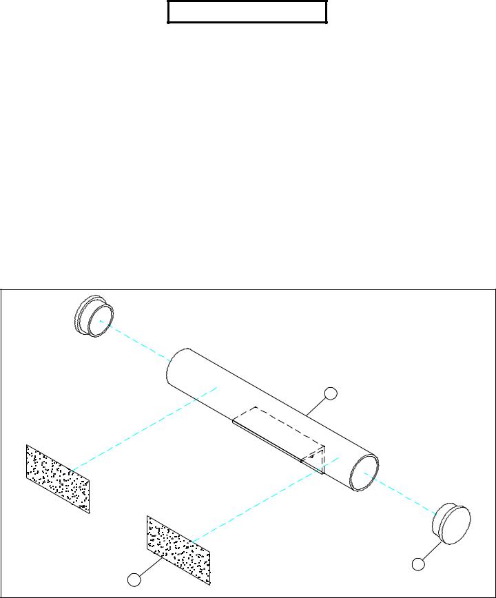
5 |
|
28 |
FIGURE 1 |
32 |
|
STEP 1:
•Insert two 2-1/2” ROUND END CAPS (28) to the LOW ROWATTACHMENT (5) as shown in FIGURE 1.
•Attach two NON-SKID STRIPS (32) to the LOW ROWATTACHMENT (5) as shown in FIGURE 1.
4
|
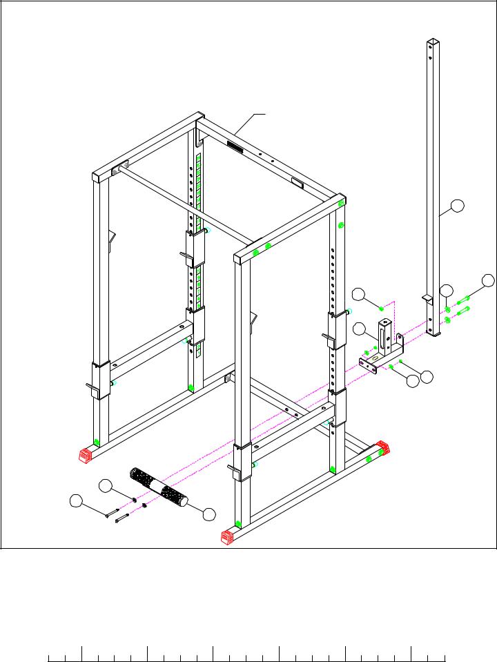
POWER RACK |
|
|
|
|
1 |
|
|
|
1/2 X 3” |
24 |
|
26 |
25 |
|
|
|
|
|
|
8 |
|
|
|
|
20 21 |
|
|
20 |
|
|
3/8 X 3-1/4” |
19 |
|
|
|
5 |
|
|
FIGURE 2 |
|
|
|
STEP 2:
•Assemble the LOW ROW ATTACHMENT (5) and the LOW PULLEY HOUSING (8) to the POWER RACK using two 3/8 X 3-1/4” BOLTS (19), four 3/8” WASHERS (20), and two 3/8” LOCK NUTS (21). See FIGURE 2.
•SECURELY assemble the UPRIGHT (1) to the LOW PULLEY HOUSING (8) using two 1/2 X 3” BOLTS (24), two 1/2” WASHERS (25), and one 1/2” LOCK NUTS (26). See FIGURE 2.
|
1/2 |
|
1/2 |
|
1/2 |
|
1/2 |
|
1/2 |
|
|
1/2 |
0 |
1 |
2 |
3 |
4 |
5 |
6 |
||||||
5
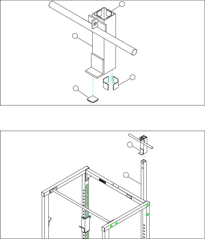
31
7
31
30
FIGURE 3
STEP 3:
•Apply eight 1” SQ. GLIDES (31) to the inside of the CARRIAGE (7) as shown in FIGURE 3.
•Attach one 1-1/4” SQ. RUBBER BUMPER (30) to the bottom of the CARRIAGE (7) as shown in FIGURE 3.
7
1
FIGURE 4
STEP 4:
• CAREFULLY slide the CARRIAGE (7) over the UPRIGHT (1) as shown in FIGURE 4.
6
 Loading...