


8210 LAT PULLDOWN/LOW ROW
ASSEMBLY INSTRUCTIONS
Part # 6776201 |
1 |
Revision:7/9/98 |
IMPORTANT NOTES
Please note:
*Thank you for purchasing the LIFE FITNESS 8210 LAT PULLDOWN/LOW ROW. Please read these instructions thoroughly and keep them for future reference. This product must be assembled on a flat, level surface to assure its proper function.
*We recommend cleaning your product (pads and frame) on a regular basis, using warm soapy water. Touch-up paint can be purchased from your LIFE FITNESS customer service representative at (800) 328-9714.
There is a risk assumed by individuals who use this type of equipment. To minimize risk, please follow these rules:
1.Inspect equipment daily. Tighten all loose connections and replace worn parts immediately. Failure to do so may result in serious injury.
2.Do not allow minors or children to play on or around this equipment.
3.Exercise with care to avoid injury.
4.If unsure of proper use of equipment, call your local LIFE FITNESS STRENGTH distributor or call the LIFE FITNESS STRENGTH customer service department at (800) 328-9714.
5.Consult your physician before beginning any exercise program.
Tools Required for Assembly
*Rubber mallet or hammer
*3/4” wrench, 9/16” wrench
*Ratchet with 3/4” and 9/16” sockets
*5/32”, 3/16”, 7/32” Allen wrenches
*Adjustable wrench
*Tape measure
Bolt Length Ruler
NOTE: BOLT LENGTH IS MEASURED FROM THE UNDERSIDE OF THE HEAD OF THE BOLT.
 BOLT LENGTH
BOLT LENGTH RULER:
|
1/2 |
|
1/2 |
|
1/2 |
|
1/2 |
|
1/2 |
|
|
1/2 |
|
|||||||||||
0 |
|
|
1 |
|
|
2 |
|
|
3 |
|
|
4 |
|
|
5 |
|
6 |
|||||||
|
|
|
|
|
|
|
|
|
|
|
|
|
|
|
|
|
|
|
|
|
|
|
|
|
2
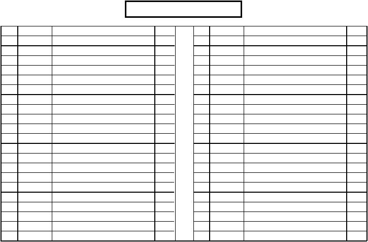
PARTS LIST
KEY |
PART # |
DESCRIPTION |
QTY |
KEY |
PART # |
DESCRIPTION |
QTY |
1 |
6775503 |
BENCH FRAME |
1 |
22 |
3102922 |
3/8 X 2-3/4” BOLT |
7 |
2 |
6775103 |
TOP BOOM |
1 |
23 |
3202401 |
3/8 X 1” BUTTON HEAD |
5 |
3 |
6774602 |
KNEE SUPPORT |
1 |
24 |
3102502 |
1/2 “ WASHER |
12 |
4 |
6778103 |
UPRIGHT |
1 |
25 |
3102501 |
3/8" WASHER |
9 |
5 |
6774302 |
FOOT SUPPORT |
1 |
26 |
3102801 |
1/2" LOCKNUT |
13 |
6 |
6792403 |
TOWER |
1 |
27 |
3102802 |
3/8" LOCKNUT |
8 |
7 |
6777703 |
TOWER BRACE |
1 |
28 |
6480301 |
3/8" FLANGE SPACER |
8 |
8 |
6489902 |
2 X 7-1/4” PLATE |
2 |
29 |
6412001 |
3/8" SPRING PIN |
1 |
9 |
6275301 |
LAT BAR |
1 |
30 |
3103801 |
5/16” SNAP HOOK |
2 |
10 |
6678201 |
DOUBLE D CHROME HANDLE |
1 |
31 |
3103302 |
13/16” SHAFT COLLAR |
2 |
11 |
6781701 |
112-3/4” LOW ROW CABLE |
1 |
32 |
3103304 |
1-5/16” SHAFT COLLAR |
2 |
12 |
6781501 |
122-3/4” LAT CABLE |
1 |
33 |
6284501 |
WEIGHT STACK SHAFT |
1 |
13 |
3116101 |
4-1/2” PULLEY |
7 |
34 |
6714601 |
HEAD PLATE |
1 |
14 |
6772301 |
21-1/2” TUBE |
1 |
35 |
6214401 |
SELECTOR PIN |
1 |
15 |
6523401 |
GUIDE ROD |
2 |
36 |
6214501 |
WEIGHT PLATE |
20 |
16 |
6677204 |
SEAT PAD |
1 |
37 |
3108002 |
WEIGHT STACK CUSHION |
2 |
17 |
6764901 |
ROLLER PAD |
2 |
38 |
3105301 |
5/8” CAP PLUG |
2 |
18 |
3102917 |
1/2 X 4" BOLT |
12 |
39 |
6382301 |
PLATE BUSHING (10 COUNT) |
4 |
19 |
3102910 |
1/2 X 3" BOLT |
2 |
40 |
6703801 |
WEIGHT STACK LABELS LBS. |
1 |
20 |
3102901 |
3/8 X 1-1/4” |
1 |
41 |
6189501 |
WEIGHT STACK LABELS (1-25) |
1 |
21 |
3102902 |
3/8 X 2-1/4" BOLT |
3 |
42 |
6791102 |
SHROUD |
1 |
3
6
38
26 24
1
18 1/2 X 4”
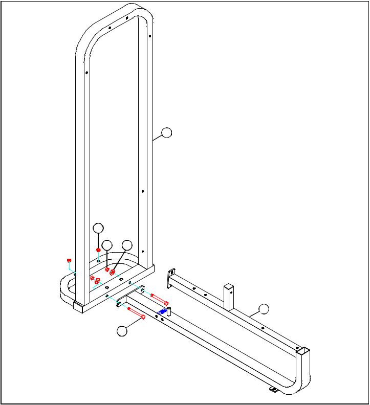
FIGURE 1
STEP 1:
•LOOSELY assemble the BENCH FRAME (1) to the TOWER (6) using two 1/2 X 4” BOLTS (18), two 1/2” WASHERS (24), and two 1/2” LOCK NUTS (26) as shown in FIGURE 1.
•If the machine is not going to be bolted to the floor, insert two 5/8” CAP PLUGS (38) into the TOWER
(6) as shown in FIGURE 1.
|
1/2 |
|
1/2 |
|
1/2 |
|
1/2 |
|
1/2 |
|
|
1/2 |
|
|||||||||||
0 |
|
|
1 |
|
|
2 |
|
|
3 |
|
|
4 |
|
|
5 |
|
6 |
|||||||
|
|
|
|
|
|
|
|
|
|
|
|
|
|
|
|
|
|
|
|
|
|
|
|
|
4
4
26 24
18 1/2 X 4”
1
26
18 1/2 X 4”
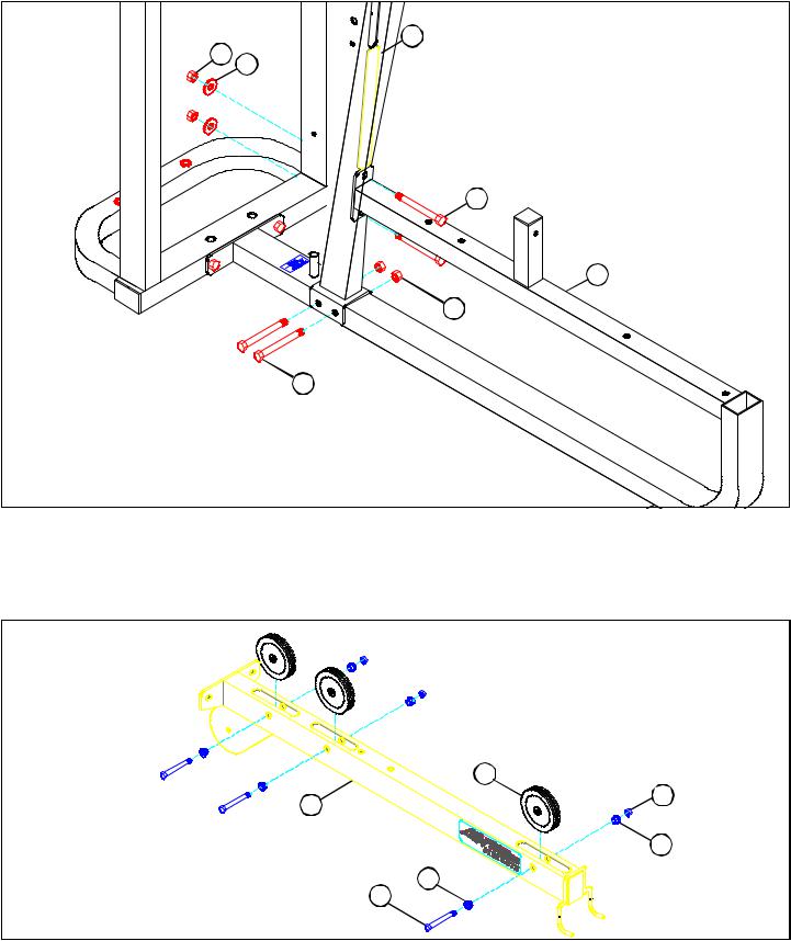
FIGURE 2
STEP 2:
•LOOSELY assemble the UPRIGHT (4) to the BENCH FRAME (1) using four 1/2 X 4” BOLTS (18), two 1/2” WASHERS (24), and four 1/2” LOCK NUTS (26) as shown in FIGURE 2.
13
27
2
28
28
3/8 X 2-3/4” 22
FIGURE 3
STEP 3:
•SECURELY assemble three 4-1/2” PULLEYS (13) to the TOP BOOM (2) using three 3/8 X 2-3/4” BOLTS (22), six 3/8” FLANGE SPACERS (28), and three 3/8” LOCK NUTS (27) as shown in FIGURE 3.
5
 Loading...