


Machine for |
LH 80 M |
|
|
Industrial Applications |
litronic` |
|
Operating Weight: 76,200 – 78,100 kg |
|
Engine Output: 230 kW / 313 HP |

Technical Data


 Engine
Rating per ISO 9249 230 kW (313 HP) at 1,700 RPM
Model Liebherr D936 according to level IIIB / Tier 4i Type 6 cylinder in-line
Bore/Stroke 122/150 mm Displacement 10.5 l
Engine operation 4-stroke diesel Common-Rail
turbo-charged and after-cooled reduced emissions
Cooling water-cooled with integrated motor oil cooler
Air cleaner dry-type air cleaner with pre-cleaner, primary and safety elements
Fuel tank 910 l
Engine idling sensor controlled Electrical system
Voltage 24 V
Batteries 2 x 170 Ah/12 V
Alternator three phase current 28 V/100 A Standard Liebherr particle filter


 Hydraulic System
Hydraulic pump for attachment
and travel drive two Liebherr variable flow, swashplate pumps (double construction)
Max. flow 2 x 350 l/min. Max. pressure 350 bar
Pump regulation electro-hydraulic with electronic engine speed sens ing regulation, pressure compensation, flow compensation, automatic oil flow optimizer
Hydraulic pump
for swing drive reversible, variable flow, swashplate pump, closedloop circuit
Max. flow 185 l/min. Max. pressure 380 bar
Hydraulic tank 390 l Hydraulic system 910 l
Hydraulic oil filter 2 full flow filters in return line with integrated fine filter area (5 μm)
Hydraulic oil cooler cooling system, consisting of a cooling unit for water and charge air and a 2nd cooler for hydraulic oil, each with an infinitely variable, thermostatically controlled fan drive system
MODE selection adjustment of engine and hydraulic performance via a mode pre-selector to match application, e.g. for especially economical and environmentally friendly operation or for maximum material handling and heavy-duty jobs
S (Sensitive) for precision work and lifting through very sensitive movements
E (ECO) for especially economical and environmentally friendly operation
P (Power) for maximum digging power and heavy duty jobs Tool Control ten preadjustable pump flows and pressures for add
on tools


 Hydraulic Controls
Power distribution via control valves in single block with integrated safety valves
Servo circuit
Attachment and swing with hydraulic pilot control and proportional joystick levers
Travel electroproportional via foot pedal Additional functions via switch or electroproportional foot pedals
Option Liebherr-Proportional-Control, proportionally acting transmitters on the joysticks for additional hydraulic functions

 Swing Drive
Drive by Liebherr swash plate motor in a closed system with integrated brake valve
Transmission Liebherr planetary reduction gear
Swing ring Liebherr, sealed single race ball bearing swing ring, internal teeth
Swing speed 0 – 6.4 RPM stepless Swing torque 154 kNm
Holding brake spring applied – pressure released Option pedal controlled positioning brake


 Operator’s Cab
Cab safety cab structure with individual windscreens or featuring a slide-in subpart under the ceiling, work headlights integrated in the ceiling, a door with a side window (can be opened on both sides), large stowing and depositing possibilities, shockabsorbing suspension, sounddamping insulating, tinted laminated safety glass, separate shades for the sunroof window and windscreen
Operator’s seat Standard air cushioned operator’s seat with headrest, lap belt, seat heater, manual weight adjustment, adjustable seat cushion inclination and length and mechanical lumbar vertebrae support
Operator’s seat Comfort
(Option) in addition to operator’s seat standard: lockable horizontal suspension, automatic weight adjustment, adjustable suspension stiffness, pneumatic lumbar vertebrae support and passive seat climatisation with active coal
Operator’s seat Premium
(Option) in addition to operator’s seat comfort: active elec tronic weight adjustment (automatic readjustment), pneumatic low frequency suspension and active seat climatisation with active coal and ventilator
Control system joysticks with arm consoles and swivel seat Operation and displays large high-resolution operating unit, selfexplanatory,
colour display with touchscreen, video-compatible, numerous setting, control and monitoring options, e.g. air conditioning control, fuel consumption, machine and tool parameters
Air-conditioning automatic air-conditioning, recirculated air function, fast de-icing and demisting at the press of a button, air vents can be operated via a menu; recirculated air and fresh air filters can be easily replaced and are accessible from the outside; heating-cooling unit, designed for extreme out-side temperatures, sensors for solar radiation, inside and outside temperatures
Noise emission
ISO 6396 LpA (inside cab) = 71 dB(A) 2000/14/EC LWA (surround noise) = 105 dB(A)


 Undercarriage
Type torsion-resistant box design made from high-strength steel plate, designed for the toughest requirements
Drive variable flow swashplate motor with automatic brake valve
Travel speed 0 – 10 km/h stepless
Driving operation automotive driving using accelerator pedal, cruise control function: storage of variable accelerator pedal positions
Axles 90 t drive axles; manual or automatic hydraulically controlled front axle oscillation lock
Service brake wet, maintenance-free, low backlash multi disc brakes
Holding brake wet, maintenance-free multi disc brakes Stabilization 4-point outriggers


 Uppercarriage
Type slewing platform made from high-strength steel plate, designed for the toughest requirements
Attachment |
Type high-strength steel plates at highlystressed points for the toughest requirements. Complex and stable mountings of attachment and cylinders.
Hydraulic cylinders Liebherr cylinders with special seal system. Shock absorption
Energy recovering cylinder Liebherr gas cylinder with special sealing and control system
Bearings sealed, low maintenance
Lubrication Liebherr full-automatic central lubrication system (country-dependent)
2 LH 80 M Litronic Machine for Industrial Applications
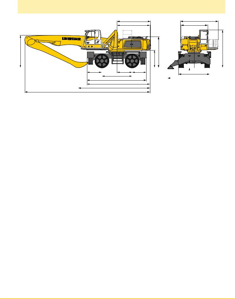
Dimensions
E |
A1 |
D |
A |
W |
C |
H |
K
Q |
|
|
T4 |
|
|
|
M |
|
|
T1 |
|
|
|
|
B |
|
|
|
|
|
|
|
|
|
|
|
|
|
|
|
||||
|
|
|
|
|
||||||||||||
|
|
|
|
|
L |
|
|
|
|
|
|
|
|
|
||
|
|
|
|
|
U4 |
|
|
|
|
|
B1 |
|||||
|
|
|
|
|
|
|
|
|
|
|||||||
|
|
|
|
|
|
|
|
|
|
|
|
|
||||
|
|
|
|
|
Z |
|
|
|
|
|
|
|
|
|||
|
|
|
|
|
V |
|
|
|
|
|
|
|
|
|||
X
|
mm |
A |
3,190 |
A1 |
4,530 |
B |
3,800 |
B1 |
6,350 |
C |
4,530 |
D |
3,950 |
E |
3,950 |
H |
3,725 |
K |
2,095 |
L |
3,600 |
M |
1,800 |
Q |
535 |
T1 |
1,700 |
T4 |
1,775 |
U4 |
7,075 |
Z |
7,525 |
E = Tail radius
Tires 23.5-25
Industrial-Type Straight Mono Boom 10.50 m |
|
|||
and Industrial Stick |
m |
7.80 |
9.00 |
|
V |
|
mm |
8,550 |
7,450 |
W |
|
mm |
4,100 |
4,500 |
X |
|
mm |
15,150 |
15,100 |
|
|
|
|
|
Industrial-Type Straight Mono Boom 11.50 m |
|
|||
and Industrial Stick |
m |
9.00 |
10.00 |
|
V |
|
mm |
8,300 |
7,600 |
W |
|
mm |
4,200 |
5,300 |
X |
|
mm |
16,150 |
16,050 |
|
|
|
|
|
Industrial-Type Angled Mono Boom 11.50 m |
|
|||
and Industrial Stick |
m |
9.00 |
10.00 |
|
V |
|
mm |
8,250 |
7,550 |
W |
|
mm |
5,300 |
5,950 |
X |
|
mm |
16,150 |
16,050 |
|
|
|
|
|
Industrial-Type Straight Mono Boom 12.50 m |
|
|||
and Industrial Stick |
m |
9.00 |
10.00 |
|
V |
|
mm |
9,100 |
8,350 |
W |
|
mm |
3,850 |
4,500 |
X |
|
mm |
17,100 |
17,100 |
LH 80 M Litronic Machine for Industrial Applications 3
Industrial Attachment
with Industrial-Type Straight Mono Boom 10.50 m
ft |
m |
|
|
|
|
|
|
|
|
|
|
|
|
|
70 |
22 |
|
|
|
|
|
|
|
|
|
|
|
|
|
|
|
|
|
|
|
|
|
|
|
|
|
|
|
|
65 |
20 |
|
|
|
|
|
|
|
|
|
|
|
|
|
60 |
18 |
|
|
|
|
|
|
|
|
|
|
|
|
|
|
|
|
|
|
|
|
|
|
|
|
|
|
|
|
55 |
16 |
|
|
|
|
|
|
|
|
|
|
|
|
|
50 |
|
|
|
|
|
|
|
|
|
|
|
|
|
|
|
|
|
|
|
|
|
|
|
|
|
|
|
|
|
45 |
14 |
|
|
|
|
|
|
|
|
|
|
|
|
|
|
|
|
|
|
|
|
|
|
|
|
|
|
|
|
40 |
12 |
|
|
|
|
|
|
|
|
|
|
|
|
|
|
|
|
|
|
|
|
|
|
|
|
|
|
|
|
35 |
10 |
|
|
|
|
|
|
|
|
|
|
|
|
|
30 |
|
|
|
|
|
|
|
|
|
|
|
|
|
|
|
|
|
|
|
|
|
|
|
|
|
|
|
|
|
25 |
8 |
|
|
|
|
|
|
|
|
|
|
|
|
|
|
|
|
|
|
|
|
|
|
|
|
|
|
|
|
20 |
6 |
|
|
|
|
|
|
|
|
|
|
|
|
|
15 |
4 |
|
|
|
|
|
|
|
|
|
|
|
|
|
|
|
|
|
|
|
|
|
|
|
|
|
|
|
|
10 |
|
|
|
|
|
|
|
|
|
|
|
|
|
|
5 |
2 |
|
|
|
|
|
|
|
|
|
|
|
|
|
|
|
|
|
|
|
|
|
|
|
|
|
|
|
|
0 |
0 |
|
|
|
|
|
|
|
|
|
|
|
|
|
-5 |
-2 |
|
|
|
|
|
|
|
|
|
|
|
|
|
|
|
|
|
|
|
|
|
|
|
|
|
|
|
|
-10 |
|
|
|
|
|
|
|
|
|
|
|
|
|
|
-15 |
-4 |
|
|
|
|
|
1 |
|
|
|
|
|
|
|
|
|
|
|
|
|
|
|
|
|
|
|
|
||
-20 |
-6 |
|
|
|
|
|
2 |
|
|
|
|
|
|
|
|
|
|
|
|
|
|
|
|
|
|
|
|
||
-25 |
-8 |
|
|
|
|
|
3 |
|
|
|
|
|
|
|
|
|
|
|
|
|
4 |
|
|
|
|
|
|
|
|
|
|
|
|
|
|
|
|
|
|
|
|
|
|
|
|
20 |
18 |
16 |
14 |
12 |
10 |
|
8 |
6 |
4 |
|
2 |
0 m |
|
|
65 |
60 |
55 |
50 |
45 |
40 |
35 |
30 |
25 |
20 |
15 |
10 |
5 |
0 ft |
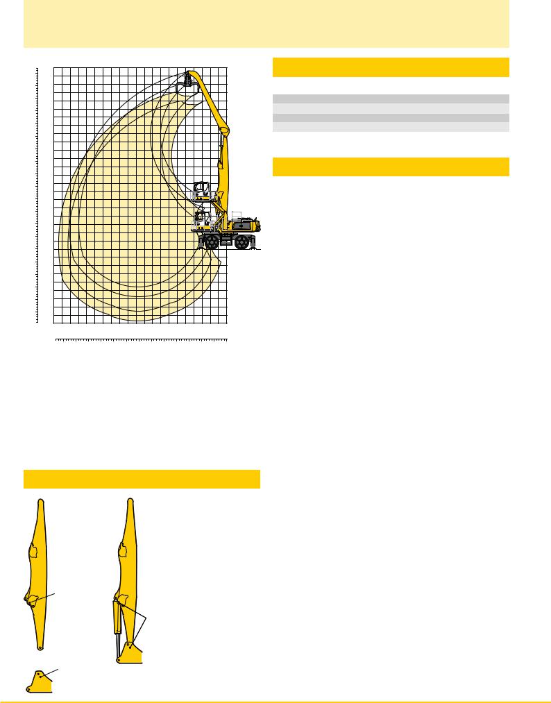
Attachment Envelope
Kinematic variant 2A
1 with industrial stick 7.80 m
2 with industrial stick 9.00 m
3 with industrial stick 7.80 m and grapple model GMM 80-5 4 with industrial stick 9.00 m and grapple model GMM 80-5
Operating Weight
The operating weight includes basic machine with 4 pt. outriggers, hydr. cab elevation, 4 solid tires and industrial attachment with indus- trial-type straight mono boom 10.50 m.
with grapple model GMM 80-5/1.70 m3 semi-closed tines |
Weight |
and industrial stick 7.80 m |
76,200 kg |
and industrial stick 9.00 m |
76,700 kg |
Kinematic Variant 2A
Hole A
2A
Hole 2
Energy recovery with kinematic variant 2A
4 LH 80 M Litronic Machine for Industrial Applications
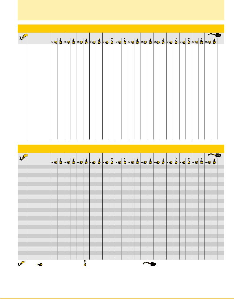
Lift Capacities
with Industrial-Type Straight Mono Boom 10.50 m (Kinematic Variant 2A)
Industrial Stick 7.80 m
4.5 m 6.0 m 7.5 m 9.0 m 10.5 m 12.0 m 13.5 m 15.0 m 16.5 m 18.0 m 19.5 m 21.0 m
m |
Undercarriage |
m |
24.0 |
Stabilizers raised |
|
|
|
|
|
|
|
|
|
|
|
|
|
|
|
|
|
|
|
|
|
4 pt. outriggers down |
|
|
|
|
|
|
|
|
|
|
|
|
|
|
|
|
|
|
|
|
|
|
22.5 |
Stabilizers raised |
|
|
|
|
|
|
|
|
|
|
|
|
|
|
|
|
|
|
|
|
|
4 pt. outriggers down |
|
|
|
|
|
|
|
|
|
|
|
|
|
|
|
|
|
|
|
|
|
|
21.0 |
Stabilizers raised |
|
|
|
|
|
|
|
|
|
|
|
|
|
|
|
|
|
|
|
|
|
4 pt. outriggers down |
|
|
|
|
|
|
|
|
|
|
|
|
|
|
|
|
|
|
|
|
|
|
19.5 |
Stabilizers raised |
|
|
15.0* |
15.0* |
|
|
|
|
|
|
|
|
|
|
|
|
|
|
13.0* |
13.0* |
7.0 |
4 pt. outriggers down |
|
|
15.0* |
15.0* |
|
|
|
|
|
|
|
|
|
|
|
|
|
|
13.0* |
13.0* |
||
18.0 |
Stabilizers raised |
|
|
|
|
14.8* |
14.8* |
12.6* |
12.6* |
|
|
|
|
|
|
|
|
|
|
10.6* |
10.6* |
9.9 |
4 pt. outriggers down |
|
|
|
|
14.8* |
14.8* |
12.6* |
12.6* |
|
|
|
|
|
|
|
|
|
|
10.6* |
10.6* |
||
16.5 |
Stabilizers raised |
|
|
|
|
15.7* |
15.7* |
14.4* |
14.4* |
11.6 |
12.5* |
|
|
|
|
|
|
|
|
9.0 |
9.5* |
11.9 |
4 pt. outriggers down |
|
|
|
|
15.7* |
15.7* |
14.4* |
14.4* |
12.5* |
12.5* |
|
|
|
|
|
|
|
|
9.5* |
9.5* |
||
15.0 |
Stabilizers raised |
|
|
|
|
|
|
15.4* |
15.4* |
11.9 |
13.1 |
9.2 |
10.2 |
|
|
|
|
|
|
7.2 |
8.1 |
13.4 |
4 pt. outriggers down |
|
|
|
|
|
|
15.4* |
15.4* |
13.8* |
13.8* |
12.1* |
12.1* |
|
|
|
|
|
|
8.8* |
8.8* |
||
13.5 |
Stabilizers raised |
|
|
|
|
|
|
15.3* |
15.3* |
11.9 |
13.2 |
9.3 |
10.3 |
7.3 |
8.1 |
|
|
|
|
6.1 |
6.8 |
14.6 |
4 pt. outriggers down |
|
|
|
|
|
|
15.3* |
15.3* |
13.7* |
13.7* |
12.5* |
12.5* |
11.4* |
11.4* |
|
|
|
|
8.4* |
8.4* |
||
12.0 |
Stabilizers raised |
|
|
|
|
|
|
15.4* |
15.4* |
11.9 |
13.1 |
9.3 |
10.3 |
7.4 |
8.2 |
5.8 |
6.5 |
|
|
5.3 |
6.0 |
15.6 |
4 pt. outriggers down |
|
|
|
|
|
|
15.4* |
15.4* |
13.8* |
13.8* |
12.5* |
12.5* |
11.5* |
11.5* |
10.0* |
10.0* |
|
|
8.1* |
8.1* |
||
10.5 |
Stabilizers raised |
|
|
|
|
17.3* |
17.3* |
15.1 |
15.7* |
11.6 |
12.8 |
9.1 |
10.1 |
7.3 |
8.1 |
5.8 |
6.5 |
|
|
4.8 |
5.4 |
16.3 |
4 pt. outriggers down |
|
|
|
|
17.3* |
17.3* |
15.7* |
15.7* |
13.9* |
13.9* |
12.6* |
12.6* |
11.5* |
11.5* |
10.6* |
10.6* |
|
|
7.9* |
7.9* |
||
9.0 |
Stabilizers raised |
|
|
|
|
18.6* |
18.6* |
14.6 |
16.1 |
11.2 |
12.4 |
8.8 |
9.8 |
7.1 |
7.9 |
5.7 |
6.4 |
4.6 |
5.3 |
4.3 |
4.9 |
16.9 |
4 pt. outriggers down |
|
|
|
|
18.6* |
18.6* |
16.1* |
16.1* |
14.2* |
14.2* |
12.8* |
12.8* |
11.6* |
11.6* |
10.7* |
10.7* |
9.6* |
9.6* |
7.9* |
7.9* |
||
7.5 |
Stabilizers raised |
|
|
19.4* |
19.4* |
18.6 |
19.5* |
13.8 |
15.3 |
10.7 |
11.9 |
8.5 |
9.4 |
6.8 |
7.7 |
5.6 |
6.3 |
4.6 |
5.2 |
4.0 |
4.6 |
17.4 |
4 pt. outriggers down |
|
|
19.4* |
19.4* |
19.5* |
19.5* |
16.7* |
16.7* |
14.6* |
14.6* |
13.0* |
13.0* |
11.8* |
11.8* |
10.7* |
10.7* |
9.7 |
9.8* |
7.9* |
7.9* |
||
6.0 |
Stabilizers raised |
26.3* |
26.3* |
24.3 |
25.5* |
17.1 |
19.2 |
12.9 |
14.4 |
10.1 |
11.2 |
8.1 |
9.0 |
6.6 |
7.4 |
5.4 |
6.1 |
4.4 |
5.1 |
3.8 |
4.4 |
17.7 |
4 pt. outriggers down |
26.3* |
26.3* |
25.5* |
25.5* |
20.6* |
20.6* |
17.4* |
17.4* |
15.1* |
15.1* |
13.3* |
13.3* |
12.0* |
12.0* |
10.8* |
10.8* |
9.6 |
9.8* |
7.9* |
7.9* |
||
4.5 |
Stabilizers raised |
19.0* |
19.0* |
21.5 |
24.5 |
15.6 |
17.5 |
11.9 |
13.3 |
9.4 |
10.5 |
7.6 |
8.5 |
6.2 |
7.0 |
5.2 |
5.9 |
4.3 |
4.9 |
3.7 |
4.2 |
17.9 |
4 pt. outriggers down |
19.0* |
19.0* |
27.5* |
27.5* |
21.8* |
21.8* |
18.1* |
18.1* |
15.5* |
15.5* |
13.6* |
13.6* |
12.1* |
12.1* |
10.9* |
10.9* |
9.4 |
9.7* |
8.1* |
8.1* |
||
3.0 |
Stabilizers raised |
3.9* |
3.9* |
19.0 |
20.2* |
14.0 |
16.0 |
10.9 |
12.3 |
8.7 |
9.9 |
7.1 |
8.1 |
5.9 |
6.7 |
5.0 |
5.6 |
4.2 |
4.8 |
3.6 |
4.1 |
17.9 |
4 pt. outriggers down |
3.9* |
3.9* |
20.2* |
20.2* |
22.7* |
22.7* |
18.7* |
18.7* |
15.9* |
15.9* |
13.8* |
13.8* |
12.2* |
12.2* |
10.7 |
10.8* |
9.3 |
9.6* |
8.1* |
8.1* |
||
1.5 |
Stabilizers raised |
3.2* |
3.2* |
10.5* |
10.5* |
12.8 |
14.7 |
10.1 |
11.5 |
8.2 |
9.3 |
6.7 |
7.7 |
5.6 |
6.4 |
4.8 |
5.5 |
4.1 |
4.7 |
3.6 |
4.1 |
17.8 |
4 pt. outriggers down |
3.2* |
3.2* |
10.5* |
10.5* |
23.2* |
23.2* |
19.0* |
19.0* |
16.1* |
16.1* |
13.9* |
13.9* |
12.1* |
12.1* |
10.5 |
10.7* |
9.1 |
9.2* |
7.6* |
7.6* |
||
0 |
Stabilizers raised |
4.0* |
4.0* |
9.0* |
9.0* |
12.0 |
13.8 |
9.5 |
10.9 |
7.7 |
8.8 |
6.4 |
7.3 |
5.4 |
6.2 |
4.6 |
5.3 |
4.0 |
4.6 |
3.6 |
4.2 |
17.6 |
4 pt. outriggers down |
4.0* |
4.0* |
9.0* |
9.0* |
20.9* |
20.9* |
18.8* |
18.8* |
15.9* |
15.9* |
13.7* |
13.7* |
11.9* |
11.9* |
10.3* |
10.3* |
8.6* |
8.6* |
7.0* |
7.0* |
||
– 1.5 |
Stabilizers raised |
|
|
9.4* |
9.4* |
11.5 |
13.3 |
9.1 |
10.4 |
7.4 |
8.5 |
6.2 |
7.1 |
5.2 |
6.0 |
4.5 |
5.2 |
3.9 |
4.5 |
3.8 |
4.4 |
17.0 |
4 pt. outriggers down |
|
|
9.4* |
9.4* |
17.8* |
17.8* |
18.0* |
18.0* |
15.3* |
15.3* |
13.1* |
13.1* |
11.2* |
11.2* |
9.5* |
9.5* |
7.6* |
7.6* |
6.8* |
6.8* |
||
– 3.0 |
Stabilizers raised |
|
|
|
|
11.3 |
13.1 |
8.8 |
10.2 |
7.2 |
8.3 |
6.0 |
6.9 |
5.1 |
5.9 |
4.4 |
5.1 |
|
|
4.3 |
4.9 |
15.5 |
4 pt. outriggers down |
|
|
|
|
17.4* |
17.4* |
16.3* |
16.3* |
14.0* |
14.0* |
11.9* |
11.9* |
10.1* |
10.1* |
8.2* |
8.2* |
|
|
7.5* |
7.5* |
||
– 4.5 |
Stabilizers raised |
|
|
|
|
|
|
|
|
7.2 |
8.3 |
|
|
|
|
|
|
|
|
6.0 |
6.9 |
12.0 |
4 pt. outriggers down |
|
|
|
|
|
|
|
|
11.9* |
11.9* |
|
|
|
|
|
|
|
|
10.1* |
10.1* |
||
– 6.0 |
Stabilizers raised |
|
|
|
|
|
|
|
|
|
|
|
|
|
|
|
|
|
|
|
|
|
4 pt. outriggers down |
|
|
|
|
|
|
|
|
|
|
|
|
|
|
|
|
|
|
|
|
|
|
– 7.5 |
Stabilizers raised |
|
|
|
|
|
|
|
|
|
|
|
|
|
|
|
|
|
|
|
|
|
4 pt. outriggers down |
|
|
|
|
|
|
|
|
|
|
|
|
|
|
|
|
|
|
|
|
|
Industrial Stick 9.00 m
4.5 m 6.0 m 7.5 m 9.0 m 10.5 m 12.0 m 13.5 m 15.0 m 16.5 m 18.0 m 19.5 m 21.0 m
m |
Undercarriage |
m |
24.0 |
Stabilizers raised |
|
|
|
|
|
|
|
|
|
|
|
|
|
|
|
|
|
|
|
|
|
|
|
|
4 pt. outriggers down |
|
|
|
|
|
|
|
|
|
|
|
|
|
|
|
|
|
|
|
|
|
|
|
||
22.5 |
Stabilizers raised |
|
|
|
|
|
|
|
|
|
|
|
|
|
|
|
|
|
|
|
|
|
|
|
|
4 pt. outriggers down |
|
|
|
|
|
|
|
|
|
|
|
|
|
|
|
|
|
|
|
|
|
|
|
||
21.0 |
Stabilizers raised |
|
|
|
13.1* |
13.1* |
|
|
|
|
|
|
|
|
|
|
|
|
|
|
|
|
12.4* |
12.4* |
6.4 |
4 pt. outriggers down |
|
|
13.1* |
13.1* |
|
|
|
|
|
|
|
|
|
|
|
|
|
|
|
|
12.4* |
12.4* |
|||
19.5 |
Stabilizers raised |
|
|
|
|
|
12.9* |
12.9* |
10.9* |
10.9* |
|
|
|
|
|
|
|
|
|
|
|
|
9.6* |
9.6* |
9.7 |
4 pt. outriggers down |
|
|
|
|
12.9* |
12.9* |
10.9* |
10.9* |
|
|
|
|
|
|
|
|
|
|
|
|
9.6* |
9.6* |
|||
18.0 |
Stabilizers raised |
|
|
|
|
|
|
|
12.6* |
12.6* |
10.9* |
10.9* |
|
|
|
|
|
|
|
|
|
|
8.4* |
8.4* |
11.9 |
4 pt. outriggers down |
|
|
|
|
|
|
12.6* |
12.6* |
10.9* |
10.9* |
|
|
|
|
|
|
|
|
|
|
8.4* |
8.4* |
|||
16.5 |
Stabilizers raised |
|
|
|
|
|
|
|
13.3* |
13.3* |
12.2* |
12.2* |
9.5 |
10.5 |
7.3 |
7.9* |
|
|
|
|
|
|
7.2 |
7.7* |
13.6 |
4 pt. outriggers down |
|
|
|
|
|
|
13.3* |
13.3* |
12.2* |
12.2* |
10.6* |
10.6* |
7.9* |
7.9* |
|
|
|
|
|
|
7.7* |
7.7* |
|||
15.0 |
Stabilizers raised |
|
|
|
|
|
|
|
|
|
12.5 |
13.0* |
9.7 |
10.7 |
7.6 |
8.4 |
|
|
|
|
|
|
6.0 |
6.7 |
14.9 |
4 pt. outriggers down |
|
|
|
|
|
|
|
|
13.0* |
13.0* |
11.9* |
11.9* |
10.1* |
10.1* |
|
|
|
|
|
|
7.2* |
7.2* |
|||
13.5 |
Stabilizers raised |
|
|
|
|
|
|
|
|
|
12.5 |
12.9* |
9.8 |
10.8 |
7.7 |
8.6 |
6.1 |
6.8 |
|
|
|
|
5.1 |
5.8 |
16.0 |
4 pt. outriggers down |
|
|
|
|
|
|
|
|
12.9* |
12.9* |
11.8* |
11.8* |
10.9* |
10.9* |
9.3* |
9.3* |
|
|
|
|
6.9* |
6.9* |
|||
12.0 |
Stabilizers raised |
|
|
|
|
|
|
|
|
|
12.4 |
12.9* |
9.7 |
10.7 |
7.7 |
8.5 |
6.1 |
6.8 |
4.8 |
5.5 |
|
|
4.5 |
5.1 |
16.9 |
4 pt. outriggers down |
|
|
|
|
|
|
|
|
12.9* |
12.9* |
11.8* |
11.8* |
10.8* |
10.8* |
10.1* |
10.1* |
7.9* |
7.9* |
|
|
6.7* |
6.7* |
|||
10.5 |
Stabilizers raised |
|
|
|
|
|
|
|
14.6* |
14.6* |
12.2 |
13.1* |
9.5 |
10.5 |
7.6 |
8.4 |
6.1 |
6.8 |
4.8 |
5.5 |
|
|
4.1 |
4.6 |
17.6 |
4 pt. outriggers down |
|
|
|
|
|
|
14.6* |
14.6* |
13.1* |
13.1* |
11.9* |
11.9* |
10.9* |
10.9* |
10.1* |
10.1* |
9.4* |
9.4* |
|
|
6.6* |
6.6* |
|||
9.0 |
Stabilizers raised |
|
|
|
|
|
|
|
15.1* |
15.1* |
11.8 |
13.0 |
9.2 |
10.2 |
7.4 |
8.2 |
5.9 |
6.6 |
4.8 |
5.4 |
3.8 |
4.4 |
3.7 |
4.3 |
18.2 |
4 pt. outriggers down |
|
|
|
|
|
|
15.1* |
15.1* |
13.4* |
13.4* |
12.1* |
12.1* |
11.0* |
11.0* |
10.2* |
10.2* |
9.4* |
9.4* |
7.1* |
7.1* |
6.5* |
6.5* |
|||
7.5 |
Stabilizers raised |
|
|
|
|
|
15.8* |
15.8* |
14.6 |
15.7* |
11.2 |
12.4 |
8.8 |
9.8 |
7.1 |
7.9 |
5.7 |
6.4 |
4.7 |
5.3 |
3.8 |
4.3 |
3.5 |
4.0 |
18.6 |
4 pt. outriggers down |
|
|
|
|
15.8* |
15.8* |
15.7* |
15.7* |
13.8* |
13.8* |
12.4* |
12.4* |
11.2* |
11.2* |
10.3* |
10.3* |
9.4* |
9.4* |
8.3 |
8.5* |
6.5* |
6.5* |
|||
6.0 |
Stabilizers raised |
|
|
|
16.6* |
16.6* |
18.4 |
19.3* |
13.6 |
15.1 |
10.5 |
11.7 |
8.4 |
9.3 |
6.7 |
7.6 |
5.5 |
6.2 |
4.5 |
5.1 |
3.7 |
4.2 |
3.3 |
3.8 |
18.9 |
4 pt. outriggers down |
|
|
16.6* |
16.6* |
19.3* |
19.3* |
16.4* |
16.4* |
14.3* |
14.3* |
12.7* |
12.7* |
11.4* |
11.4* |
10.4* |
10.4* |
9.5* |
9.5* |
8.2 |
8.6* |
6.6* |
6.6* |
|||
4.5 |
Stabilizers raised |
|
30.4* |
30.4* |
23.6 |
25.5* |
16.7 |
18.7 |
12.5 |
14.0 |
9.8 |
11.0 |
7.8 |
8.8 |
6.4 |
7.2 |
5.2 |
5.9 |
4.3 |
4.9 |
3.6 |
4.1 |
3.1 |
3.7 |
19.0 |
4 pt. outriggers down |
30.4* |
30.4* |
25.5* |
25.5* |
20.5* |
20.5* |
17.2* |
17.2* |
14.8* |
14.8* |
13.0* |
13.0* |
11.6* |
11.6* |
10.5* |
10.5* |
9.4 |
9.5* |
8.1 |
8.5* |
6.7* |
6.7* |
|||
3.0 |
Stabilizers raised |
|
12.6* |
12.6* |
20.6 |
23.5 |
14.9 |
16.9 |
11.4 |
12.9 |
9.0 |
10.2 |
7.3 |
8.3 |
6.0 |
6.8 |
5.0 |
5.7 |
4.1 |
4.8 |
3.5 |
4.0 |
3.1 |
3.6 |
19.1 |
4 pt. outriggers down |
12.6* |
12.6* |
27.4* |
27.4* |
21.6* |
21.6* |
17.9* |
17.9* |
15.3* |
15.3* |
13.3* |
13.3* |
11.8* |
11.8* |
10.6* |
10.6* |
9.2 |
9.5* |
8.0 |
8.3* |
6.8* |
6.8* |
|||
1.5 |
Stabilizers raised |
|
5.1* |
5.1* |
17.8* |
17.8* |
13.4 |
15.3 |
10.4 |
11.8 |
8.3 |
9.5 |
6.8 |
7.8 |
5.6 |
6.4 |
4.7 |
5.4 |
4.0 |
4.6 |
3.4 |
3.9 |
3.0 |
3.5 |
19.0 |
4 pt. outriggers down |
5.1* |
5.1* |
17.8* |
17.8* |
22.4* |
22.4* |
18.4* |
18.4* |
15.6* |
15.6* |
13.5* |
13.5* |
11.9* |
11.9* |
10.5 |
10.5* |
9.0 |
9.3* |
7.9 |
8.0* |
6.9* |
6.9* |
|||
0 |
Stabilizers raised |
|
4.7* |
4.7* |
11.1* |
11.1* |
12.2 |
14.1 |
9.6 |
11.0 |
7.7 |
8.9 |
6.4 |
7.3 |
5.3 |
6.1 |
4.5 |
5.2 |
3.8 |
4.4 |
3.3 |
3.8 |
3.0 |
3.6 |
18.8 |
4 pt. outriggers down |
4.7* |
4.7* |
11.1* |
11.1* |
22.7* |
22.7* |
18.6* |
18.6* |
15.7* |
15.7* |
13.5* |
13.5* |
11.8* |
11.8* |
10.3 |
10.3* |
8.9 |
9.0* |
7.5* |
7.5* |
6.4* |
6.4* |
|||
– 1.5 |
Stabilizers raised |
|
5.4* |
5.4* |
10.0* |
10.0* |
11.4 |
13.3 |
9.0 |
10.4 |
7.3 |
8.4 |
6.0 |
7.0 |
5.1 |
5.9 |
4.3 |
5.0 |
3.7 |
4.3 |
3.2 |
3.8 |
3.1 |
3.7 |
18.4 |
4 pt. outriggers down |
5.4* |
5.4* |
10.0* |
10.0* |
20.7* |
20.7* |
18.3* |
18.3* |
15.4* |
15.4* |
13.2* |
13.2* |
11.4* |
11.4* |
9.9* |
9.9* |
8.4* |
8.4* |
6.6* |
6.6* |
5.9* |
5.9* |
|||
– 3.0 |
Stabilizers raised |
|
6.4* |
6.4* |
10.2* |
10.2* |
11.0 |
12.8 |
8.6 |
10.0 |
7.0 |
8.1 |
5.8 |
6.7 |
4.9 |
5.7 |
4.2 |
4.9 |
3.6 |
4.3 |
|
|
3.4 |
4.0 |
17.3 |
4 pt. outriggers down |
6.4* |
6.4* |
10.2* |
10.2* |
18.1* |
18.1* |
17.3* |
17.3* |
14.6* |
14.6* |
12.5* |
12.5* |
10.7* |
10.7* |
9.1* |
9.1* |
7.4* |
7.4* |
|
|
6.3* |
6.3* |
|||
– 4.5 |
Stabilizers raised |
|
|
|
|
|
10.8 |
12.6 |
8.4 |
9.8 |
6.8 |
7.9 |
5.7 |
6.6 |
4.8 |
5.6 |
4.2 |
4.8 |
|
|
|
|
4.0 |
4.7 |
15.4 |
4 pt. outriggers down |
|
|
|
|
17.8* |
17.8* |
15.4* |
15.4* |
13.2* |
13.2* |
11.2* |
11.2* |
9.5* |
9.5* |
7.7* |
7.7* |
|
|
|
|
7.3* |
7.3* |
|||
– 6.0 |
Stabilizers raised |
|
|
|
|
|
|
|
|
|
|
|
|
|
|
|
|
|
|
|
|
|
|
|
|
4 pt. outriggers down |
|
|
|
|
|
|
|
|
|
|
|
|
|
|
|
|
|
|
|
|
|
|
|
||
– 7.5 |
Stabilizers raised |
|
|
|
|
|
|
|
|
|
|
|
|
|
|
|
|
|
|
|
|
|
|
|
|
4 pt. outriggers down |
|
|
|
|
|
|
|
|
|
|
|
|
|
|
|
|
|
|
|
|
|
|
|
||
Height |
Can be slewed through 360° |
In longitudinal position of undercarriage |
|
|
Max. reach |
* Limited by hydr. capacity |
|
|
|||||||||||||||||
The lift capacities on the stick end without attachment are stated in metric tons (t) and are valid on a firm, level supporting surface with blocked oscillating axle. These capacities can be slewed through 360° with the undercarriage in the transverse position. Capacities in the longitudinal position of the undercarriage (+/– 15°) are specified over the steering axle with the stabilizers raised and over the rigid axle with the stabilizers down. Indicated loads comply with the ISO 10567 standard and do not exceed 75 % of tipping or 87 % of hydraulic capacity. The lift capacity values indicated are attained at the corresponding operating temperature. This operating tem perature is ensured by continuous movement of the boom. Weights of fitted working tools (grabs, load hooks, etc.) and load accommodation equipment are to be deducted from the lift capacity values. The lift capacity of the unit is limited by its stability, the lifting capability of the hydraulic elements, or the maximum permissible lifting capacity of the load hook.
In accordance with the harmonised EU Standard EN 474-5, hydraulic excavators used for lifting operations must be equipped with pipe rupture protection devices on the hoist cylinders and an overload warning device.
LH 80 M Litronic Machine for Industrial Applications 5
 Loading...