


LG 42LH20R, 42LH50YR, 42LH30FR, 47LH50YR, 22LH20R User Manual
...LCD TV
OWNER’S MANUAL
19LH20R |
32LH30FR |
19LU50R |
22LH20R |
37LH30FR |
22LU50FR |
26LH20R |
42LH30FR |
26LU50FR |
32LH20R |
47LH30FR |
|
37LH20R |
|
32LH70YR |
42LH20R |
42LH50YR |
42LH70YR |
|
47LH50YR |
47LH70YR |
32LF20FR |
55LH50YR |
|
42LF20FR |
|
42LH90QR |
|
|
47LH90QR |
Please read this manual carefully before operating your set and retain it for future reference.
The model and serial number of the TV is located on the back and one side of the TV.
Record it below should you ever need service.
Model:
Serial:
P/NO : MFL58486305 (0905-REV07)
www.lge.com
WARNING / CAUTION
TO REDUCE THE RISK OF ELECTRIC SHOCK DO NOT REMOVE COVER (OR BACK). NO USER SERVICEABLE PARTS INSIDE. REFER TO QUALIFIED SERVICE PERSONNEL.
The lightning flash with arrowhead  symbol, within an equilateral triangle, is intended to alert the user to the presence of uninsulated “dangerous voltage” within the
product’s enclosure that may be of sufficient magnitude to constitute a risk of electric shock to persons.
The exclamation point within an equilateral  triangle is intended to alert the user to the presence of important operating and maintenance (servicing) instructions in the
literature accompanying the appliance.
WARNING/CAUTION
TO REDUCE THE RISK OF FIRE AND ELECTRIC SHOCK, DO NOT EXPOSE THIS PRODUCT TO RAIN OR MOISTURE.
2
SAFETY INSTRUCTIONS
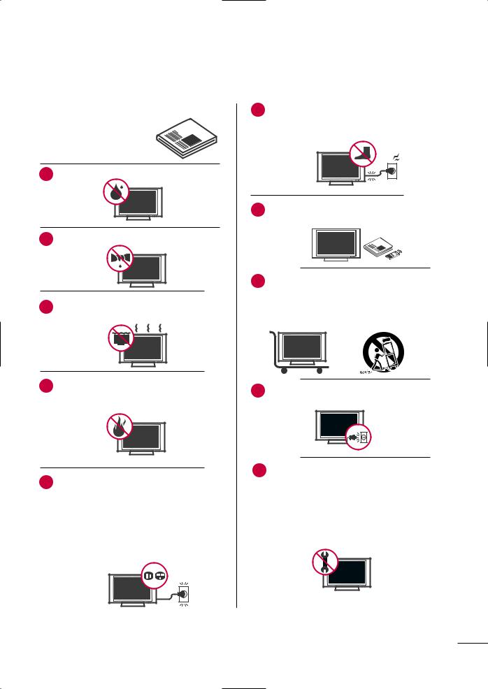
IMPORTANT SAFETY INSTRUCTIONS
Read these instructions.
Keep these instructions.
Heed all warnings.
Follow all instructions.
1
2Clean only with dry cloth.
3Do not block any ventilation openings. Install in accordance with the manufacturer’s instructions.
4Do not install near any heat sources such as radiators, heat registers, stoves, or other
apparatus (including amplifiers)that produce heat.
5Do not defeat the safety purpose of the polarized or grounding-type plug. A polarized plug has
two blades with one wider than the other. A grounding type plug has two blades and a third grounding prong, The wide blade or the third prong are provided for your safety. If the provided plug does not fit into your outlet, consult an electrician for replacement of the obsolete outlet.
6Protect the power cord from being walked on or pinched particularly at plugs, convenience
receptacles, and the point where they exit from the apparatus.
Only use attachments/accessories specified by the manufacturer.
Use only with the cart, stand, tripod, bracket, or table specified by the manufacturer, or sold with the apparatus. When a cart is used, use caution when moving the cart/apparatus combination to avoid injury from tip-over.
9Unplug this apparatus during lighting storms or when unused for long periods of time.
10 |
Refer all servicing to qualified service personnel. |
|
Servicing is required when the apparatus has |
been damaged in any way, such as powersupply cord or plug is damaged, liquid has been spilled or objects have fallen into the apparatus, the apparatus has been exposed to rain or moisture, does not operate normally, or has been dropped.
3
SAFETY INSTRUCTIONS
11 |
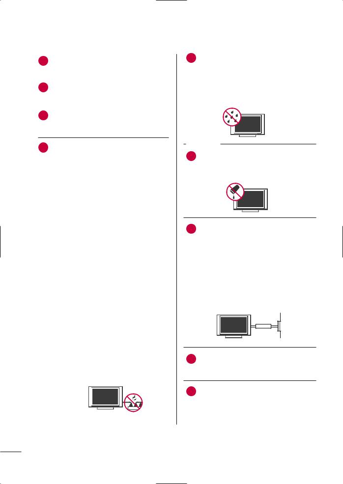
Never touch this apparatus or antenna during |
a thunder or lighting storm. |
|
|
|
|
When mounting a TV on the wall, make sure |
|
signal cables on the back of the TV. |
|
|
13 |
Do not allow an impact shock or any objects to |
fall into the product, and do not drop onto the screen with something.
CAUTION concerning the Power Cord:
upon a dedicated circuit; that is, a single outlet circuit which powers only that appliance and has no additional outlets or branch circuits. Check the specification page of this owner's manual to be certain.
Do not connect too many appliances to the same AC power outlet as this could result in fire or electric shock.
Do not overload wall outlets. Overloaded wall outlets, loose or damaged wall outlets, extension cords, frayed power cords, or damaged or cracked wire insulation are dangerous. Any of these conditions could result in electric shock or fire. Periodically examine the cord of your appliance, and if its appearance indicates damage or deterioration, unplug it, discontinue use of the appliance, and have the cord replaced with an exact replacement part by an authorized servicer. Protect the power cord from physical or mechanical abuse, such as being twisted, kinked, pinched, closed in a door, or walked upon. Pay particular attention to plugs, wall outlets, and the point where the cord exits the appliance.
Do not make the TV with the power cord plugged in. Do not use a damaged or loose power cord. Be sure do grasp the plug when unplugging the power cord. Do not pull on the power cord to unplug the TV.
15 |
of fire or electrical |
|
product to rain, |
moisture or other liquids. Do not touch the TV with wet hands. Do not install this product flammable objects such as gasoline or or expose the TV to direct air
conditioning.
Do not expose to dripping or splashing and do not place objects filled with liquids, such as vases, cups, etc. on or over the apparatus (e.g. on shelves above the unit).
GROUNDING
Ensure that you connect the earth ground wire to prevent possible electric shock (i.e. a TV with a three-prong grounded AC plug must be connected to a three-prong grounded AC outlet). If grounding methods are not possible, have a qualified electrician install a separate circuit breaker.
Do not try to ground the unit by connecting it to telephone wires, lightening rods, or gas pipes.
Power
Supply
Short-circuit
Breaker
18 DISCONNECTING DEVICE FROM MAINS Mains plug is the disconnecting device. The plug must remain readily operable.
19 As long as this unit TV is connected to the AC wall outlet, it is not disconnected from the AC power source even if you turn off this unit by SWITCH.
4
20
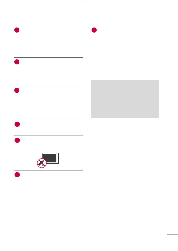
scrub gently with a soft cloth to prevent scratching. Do not spray water or other liquids directly on the TV as electric shock may occur. Do not clean with chemicals such as alcohol, thinners or benzene.
21 Moving
Make sure the product is turned off, unplugged and all cables have been removed. It may take 2 or more people to carry larger TVs. Do not press against or put stress on the front panel of the TV.
22 Ventilation
Install your TV where there is proper ventilation. Do not install in a confined space such as a bookcase. Do not cover the product with cloth or other materials (e.g.) plastic while plugged in. Do not install in excessively dusty places.
If you smell smoke or other odors coming from the TV or hear strange sounds, unplug the power cord contact an authorized service center.
Do not press strongly upon the panel with hand or sharp object such as nail, pencil or pen, or make a scratch on it.
Keep the product away from direct sunlight.
26
be a small “flicker” when it is turned on. This is normal, there is nothing wrong with TV.
Some minute dot defects may be visible on the screen, appearing as tiny red, green, or blue spots. However, they have no adverse effect on the monitor's performance.
Avoid touching the LCD screen or holding your finger(s) against it for long periods of time. Doing so may produce some temporary distortion effects on the screen.
DISPOSAL (Some models)
Hg lamp used LCD TV)
fluorescent lamp used in this product contains amount of mercury. Do not dispose of product with general household waste. of this product must be carried out in to the regulations of your local authority.
5

CONTENTS |
|
WARNING / CAUTION . . . . . . . . . . . . . . . . . . . . . . . . . . . |
. 2 |
SAFETY INSTRUCTIONS . . . . . . . . . . . . . . . . . . . . . . . . |
. . 3 |
FEATURE OF THIS TV . . . . . . . . . . . . . . . . . . . . . . . . . . . . . |
. . 8 |
PREPARATION |
|
Accessories . . . . . . . . . . . . . . . . . . . . . . . . . . . . . . . . . . . . . . . . . . . . . . . . . . . . . |
. 9 |
Front Panel Information . . . . . . . . . . . . . . . . . . . . . . . . . . . . . . . . . . . |
10 |
Back Panel Information . . . . . . . . . . . . . . . . . . . . . . . . . . . . . . . . . . . . |
13 |
Stand Instruction . . . . . . . . . . . . . . . . . . . . . . . . . . . . . . . . . . . . . . . . . . . . . |
16 |
VESA Wall Mounting . . . . . . . . . . . . . . . . . . . . . . . . . . . . . . . . . . . . . . . . |
21 |
Cable Arrangement . . . . . . . . . . . . . . . . . . . . . . . . . . . . . . . . . . . . . . . . . |
22 |
Desktop Pedestal Installation . . . . . . . . . . . . . . . . . . . . . . . . . . . |
24 |
Swivel Stand . . . . . . . . . . . . . . . . . . . . . . . . . . . . . . . . . . . . . . . . . . . . . . . . . . . |
24 |
Positioning your display . . . . . . . . . . . . . . . . . . . . . . . . . . . . . . . . . . . |
24 |
Attaching the tv to a desk . . . . . . . . . . . . . . . . . . . . . . . . . . . . . . . . |
25 |
Kensington Security System . . . . . . . . . . . . . . . . . . . . . . . . . . . . . |
25 |
Securing the TV to the wall to prevent falling when |
|
the tv is used on a stand . . . . . . . . . . . . . . . . . . . . . . . . . . . . . . . . . |
26 |
Antenna or Cable Connection . . . . . . . . . . . . . . . . . . . . . . . . . . |
27 |
EXTERNAL EQUIPMENT SETUP
HD Receiver Setup . . . . . . . . . . . . . . . . . . . . . . . . . . . . . . . . . . . . . . . . . 28
DVD Setup . . . . . . . . . . . . . . . . . . . . . . . . . . . . . . . . . . . . . . . . . . . . . . . . . . . . . . 31
VCR Setup . . . . . . . . . . . . . . . . . . . . . . . . . . . . . . . . . . . . . . . . . . . . . . . . . . . . . 33
Other A/V Source Setup . . . . . . . . . . . . . . . . . . . . . . . . . . . . . . . . . 35
PC Setup . . . . . . . . . . . . . . . . . . . . . . . . . . . . . . . . . . . . . . . . . . . . . . . . . . . . . . . . 36
USB Connection . . . . . . . . . . . . . . . . . . . . . . . . . . . . . . . . . . . . . . . . . . . . . 41
Variable Out . . . . . . . . . . . . . . . . . . . . . . . . . . . . . . . . . . . . . . . . . . . . . . . . . . . 42
Monitor Out . . . . . . . . . . . . . . . . . . . . . . . . . . . . . . . . . . . . . . . . . . . . . . . . . . . 42
WATCHING TV / CHANNEL CONTROL
Remote Control Functions . . . . . . . . . . . . . . . . . . . . . . . . . . . . . . . 43
Turning On the TV . . . . . . . . . . . . . . . . . . . . . . . . . . . . . . . . . . . . . . . . . . 46
Channel Selection . . . . . . . . . . . . . . . . . . . . . . . . . . . . . . . . . . . . . . . . . . . 46
Volume Adjustment . . . . . . . . . . . . . . . . . . . . . . . . . . . . . . . . . . . . . . . . . 46
Initializing Setup (Mode Setting) . . . . . . . . . . . . . . . . . . . . . . 47
On-Screen Menus Selection . . . . . . . . . . . . . . . . . . . . . . . . . . . . 48
Quick Menu . . . . . . . . . . . . . . . . . . . . . . . . . . . . . . . . . . . . . . . . . . . . . . . . . . . . 49
Channel Setup
- Auto Scan (Auto Tuning) . . . . . . . . . . . . . . . . . . . . . . . . . . . 50
- Add / Delete Channel (Manual Tuning) . . . . . . 51
- Channel Editing . . . . . . . . . . . . . . . . . . . . . . . . . . . . . . . . . . . . . . . . 52
Channel List . . . . . . . . . . . . . . . . . . . . . . . . . . . . . . . . . . . . . . . . . . . . . . . . . . . . 53
Favorite Channel Setup . . . . . . . . . . . . . . . . . . . . . . . . . . . . . . . . . . . . 54
Favorite Channel List . . . . . . . . . . . . . . . . . . . . . . . . . . . . . . . . . . . . . . . 55
Input List . . . . . . . . . . . . . . . . . . . . . . . . . . . . . . . . . . . . . . . . . . . . . . . . . . . . . . . . 56
Input Label . . . . . . . . . . . . . . . . . . . . . . . . . . . . . . . . . . . . . . . . . . . . . . . . . . . . . 57
AV Mode . . . . . . . . . . . . . . . . . . . . . . . . . . . . . . . . . . . . . . . . . . . . . . . . . . . . . . . . 58
Key Lock . . . . . . . . . . . . . . . . . . . . . . . . . . . . . . . . . . . . . . . . . . . . . . . . . . . . . . . . . 59
SIMPLINK . . . . . . . . . . . . . . . . . . . . . . . . . . . . . . . . . . . . . . . . . . . . . . . . . . . . . . . 60
BLUETOOTH
Bluetooth? . . . . . . . . . . . . . . . . . . . . . . . . . . . . . . . . . . . . . . . . . . . . . . . . . . . . . . 62 Setting the bluetooth . . . . . . . . . . . . . . . . . . . . . . . . . . . . . . . . . . . . . . 63 Set TV PIN . . . . . . . . . . . . . . . . . . . . . . . . . . . . . . . . . . . . . . . . . . . . . . . . . . . . . 64 Bluetooth headset . . . . . . . . . . . . . . . . . . . . . . . . . . . . . . . . . . . . . . . . . . . 65
Managing Registered Bluetooth device . . . . . . . . . . . . . 67
My Bluetooth Information . . . . . . . . . . . . . . . . . . . . . . . . . . . . . . . 68
Viewing the photos with Bluetooth device . . . . . . . . 69 Listening the Musics with Bluetooth device . . . . . . . 69
USB
Entry Modes . . . . . . . . . . . . . . . . . . . . . . . . . . . . . . . . . . . . . . . . . . . . . . . . . . . 70
Photo List . . . . . . . . . . . . . . . . . . . . . . . . . . . . . . . . . . . . . . . . . . . . . . . . . . . . . . . 71
Music List . . . . . . . . . . . . . . . . . . . . . . . . . . . . . . . . . . . . . . . . . . . . . . . . . . . . . . . 75
Movie List . . . . . . . . . . . . . . . . . . . . . . . . . . . . . . . . . . . . . . . . . . . . . . . . . . . . . . . 77
DivX Registration Code . . . . . . . . . . . . . . . . . . . . . . . . . . . . . . . . . . . 80
Deactivation . . . . . . . . . . . . . . . . . . . . . . . . . . . . . . . . . . . . . . . . . . . . . . . . . . . 81
PICTURE CONTROL
Picture Size (Aspect Ratio) Control . . . . . . . . . . . . . . . . . . 82
Preset Picture Settings - Picture Mode . . . . . . . . . . . . . 84
Manual Picture Adjustment - User Mode . . . . . . . . . . 85
Picture Improvement Technology . . . . . . . . . . . . . . . . . . . . . 86
Expert Picture control . . . . . . . . . . . . . . . . . . . . . . . . . . . . . . . . . . . . . 87
 Energy Saving . . . . . . . . . . . . . . . . . . . . . . . . . . . . . . . . . . . . . . . . . . . . . 90
Picture Reset . . . . . . . . . . . . . . . . . . . . . . . . . . . . . . . . . . . . . . . . . . . . . . . . . . . 91
Power Indicator . . . . . . . . . . . . . . . . . . . . . . . . . . . . . . . . . . . . . . . . . . . . . . . 92
Demo Mode . . . . . . . . . . . . . . . . . . . . . . . . . . . . . . . . . . . . . . . . . . . . . . . . . . . 93
Initial Setting (Factory Reset) . . . . . . . . . . . . . . . . . . . . . . . . . . . 94
6

SOUND & LANGUAGE CONTROL
Auto Volume Leveler (Auto Volume) . . . . . . . . . . . . . . . . . 95
Clear Voice ll . . . . . . . . . . . . . . . . . . . . . . . . . . . . . . . . . . . . . . . . . . . . . . . . . . 96
Preset Sound Setting (Sound Mode) . . . . . . . . . . . . . . . . 97
Sound Setting Adjustment - User Mode
- SRS TruSurround XT . . . . . . . . . . . . . . . . . . . . . . . . . . . . . . . . . 98
Balance . . . . . . . . . . . . . . . . . . . . . . . . . . . . . . . . . . . . . . . . . . . . . . . . . . . . . . . . . . 99
TV Speakers On/Off Setup . . . . . . . . . . . . . . . . . . . . . . . . . . . . 100
Selecting Audio Out . . . . . . . . . . . . . . . . . . . . . . . . . . . . . . . . . . . . . . 101
Audio Reset . . . . . . . . . . . . . . . . . . . . . . . . . . . . . . . . . . . . . . . . . . . . . . . . . 102
Stereo/SAP Broadcast Setup . . . . . . . . . . . . . . . . . . . . . . . . . . 103
On-Screen Menus Language Selection . . . . . . . . . . . . 104
Closed Captions . . . . . . . . . . . . . . . . . . . . . . . . . . . . . . . . . . . . . . . . . . . . 105
TIME SETTING
Clock Setting
- Clock Setup . . . . . . . . . . . . . . . . . . . . . . . . . . . . . . . . . . . . . . . . . . . 106
On/Off Time Setting . . . . . . . . . . . . . . . . . . . . . . . . . . . . . . . . . . . . . 107
Sleep Timer Setting . . . . . . . . . . . . . . . . . . . . . . . . . . . . . . . . . . . . . . . 108
APPENDIX
Troubleshooting . . . . . . . . . . . . . . . . . . . . . . . . . . . . . . . . . . . . . . . . . . . . 109
Maintenance . . . . . . . . . . . . . . . . . . . . . . . . . . . . . . . . . . . . . . . . . . . . . . . . . . 111
Product Specifications . . . . . . . . . . . . . . . . . . . . . . . . . . . . . . . . . . . . 112
IR Codes . . . . . . . . . . . . . . . . . . . . . . . . . . . . . . . . . . . . . . . . . . . . . . . . . . . . . .114
External Control Through RS-232C . . . . . . . . . . . . . . . . .116
7
FEATURE OF THIS TV
■ This feature is not available for all models.
 is a trademark of SRS Labs, Inc. TruSurround XT technology is incorporated under license from SRS Labs, Inc.
“DivX Certified to play DivX video, including premium content”
ABOUT DIVX VIDEO: DivX® is a digital video format created by DivX,Inc. This is an official DivX Certified device that plays DivX video. Visit www.divx.com for more information and software tools to convert your files into DivX video.
ABOUT DIVX VIDEO-ON-DEMAND: This DivX Certified® device must be registered in order to play DivX Video-on- Demand (VOD) content. To generate the registration code, locate the DivX VOD section in the device setup menu. Go to vod.divx.com with this code to complete the registration process and learn more about DivX VOD.
Manufactured under license from Dolby Laboratories. “Dolby “and the double-D symbol are trademarks of Dolby Laboratories.
 Listen to TV with wireless headset, or enjoy viewing your mobile phone photos on your TV.
Automatically enhances and amplifies the sound of human voice frequency range to help keep dialogue audible when background noise swells.
IMPORTANT INFORMATION TO PREVENT “IMAGE BURN
/BURN-IN” ON YOUR TV SCREEN
■When a fixed image (e.g. logos, screen menus, video game, and computer display) is displayed on the TV for an extended period, it can become permanently imprinted on the screen. This phenomenon is known as “image burn” or “burn-in.” Image burn is not covered under the manufacturer’s warranty.
■In order to prevent image burn, avoid displaying a fixed image on your TV screen for a prolonged period (2 or more hours for LCD, 1 or more hours for Plasma).
■Image burn can also occur on the letterboxed
areas of your TV if you use the 4:3 aspect ratio setting for an extended period.
8
PREPARATION
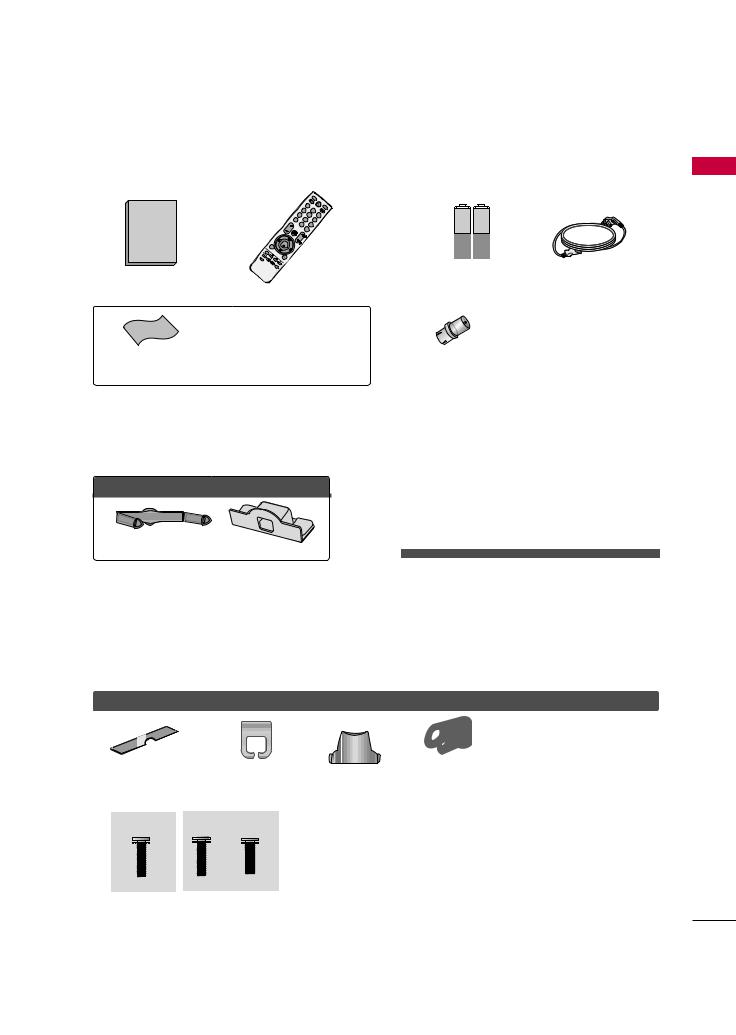
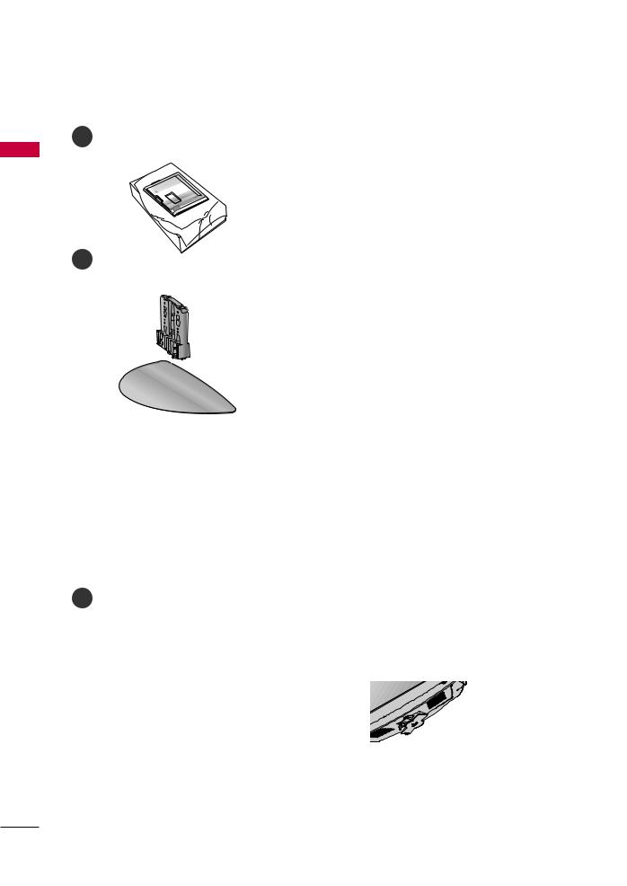
ACCESSORIES
Ensure that the following accessories are included with your TV. If an accessory is missing, please contact the dealer where you purchased the TV.
The accessories included may differ from the images below.
|
|
|
|
|
|
|
|
|
|
|
RATIO |
POWER |
|
|
|
|
|
|
|
|
|
|
|
MSLEEP |
|
|
|
|
|
|
|
|
|
|
|
|
Q. |
|
|
|
|
|
|
AV RATIO |
|
|
|
|
|
ENU |
ENERGYINPUT |
|
|
|
|
|
MODE |
|
|
|
|
|
MENU |
|
|
|
|
|
1 |
|
|
|
|
|
|
|
SAVING |
|
|
|
|
|
|
|
|
|
|
|
|
|
|
|
|
4 |
|
2 |
|
|
|
|
|
ENTER |
|
|
|
7 |
|
5 |
|
|
|
RETURN |
|
|
||
|
|
LIST |
8 |
6 |
|
|
|
|
|
|
|
|
|
VOL |
0 |
|
9 |
|
|
VOL |
MARK |
AV |
MODE |
|
|
|
|
|
Q. |
|
|
|
|
|
||||
|
|
MUTE |
|
VIEW |
or |
|
|
|
|
|
|
|
|
|
EG |
|
7 |
5 |
3 |
|
|
|
|
||
|
|
|
|
|
|
|
1 |
MU |
CH |
AP |
|
|
|
|
CH |
|
|
|
|
|
TE |
|
|
||
|
|
AP |
|
|
|
4 |
2 |
|
EG |
|
|
|
ENTER |
|
|
|
|
|
LIST |
|
|
|
|
|
|
MENU |
|
|
|
|
|
8 |
6 |
|
|
|
|
|
|
0 |
9 |
Q. |
|
Q. |
MENU |
RETURN |
VIEW |
|
|
|
|
MAR |
|
|
FAV K |
|
Owner’s Manual
Remote Control
1.5V |
1.5V |
PREPARATION |
|
Batteries |
Power Cord |
(Some models) |
|
*Wipe spots on the exterior only with the polishing cloth.
*Do not wipe roughly when removing
Polishing Cloth stain. Excessive pressure may cause
(Except 19/22LH20R, 47LH30FR, 47/55LH50YR, 19LU50R, 22LU50FR,
Screw for stand fixing 42/47LH70YR, 47LH90QR)
(Refer to P.25)
For 19/22LH20R
Cable Management Clip Protection Cover
For 26/32/37/42LH20R, 32/37/42/47LH30FR, 42/47/55LH50YR, 42/47LH90QR
(Except
55LH50YR)
Bolts for stand |
or |
|
|
assembly |
Protection Cover |
(Refer to P.17) |
|
For 32/42/47LH70YR |
|
|
You must connect it to the antenna |
|
wire after fixing in Antenna Input. |
RF Adapter |
This adapter is For supplied in |
(Some models) |
Argentina. |
For 19LU50R, 22/26LU50FR
(For 26LU50FR) (For 19LU50R, 22LU50FR)
 x 3
x 3  x 2
x 2
Bolts for stand assembly |
Cable Holder |
|
(Refer to P.23) |
||
(Refer to P.19) |
||
|
For 32/42LF20FR
or
|
|
|
(For 42/47LH70YR) |
|
|
|
|
Stand rear |
|
|
|
|
(Refer to P |
|
(For 32LH70YR) |
(For 42LH70YR) |
(For 47LH70YR) |
|
|
|
|
|
Use screws 12mm(±0.5) long on the TV assembly side. |
|
|
|
|
(sold separately) |
|
x 7 |
x 3 |
x 4 |
x 8 |
|
|
|
|
Withguidespacer |
Without guide spacer |
M4x20 |
M4x20 |
M4x16 |
M4x16 |
|
|
|
|
12mm |
12mm |
9
PREPARATION
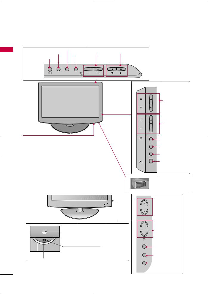
FRONT PANEL INFORMATION
■ Image shown may differ from your TV.
|
For 19/22/26/32/37/42LH20R, 32/37/42/47LH30FR |
|
||||
|
19/22/26LH20R |
MENU Button |
|
|
|
|
PREPARATION |
INPUT Button |
|
|
CHANNEL |
|
|
ENTER |
|
VOLUME |
|
|||
POWER Button |
Button |
|
(-, +) Buttons |
(E,D) Buttons |
|
|
INPUT |
MENU ENTER |
VOL |
CH |
|
|
|
|
|
|
|
|
|
|
|
|
|
|
|
32/37/42LH20R,32/37/42/47LH30FR |
|
|
|
|
|
|
CH |
CHANNEL |
|
|
|
|
|
(D,E) Buttons |
|
|
|
|
|
|
|
|
|
|
|
|
|
VOL |
VOLUME (+, -) |
|
|
|
|
|
|
Buttons |
|
Remote Control Sensor, |
|
|
|
ENTER |
Button |
|
|
|
|
|
||
|
Power/Standby Indicator |
|
|
|
|
|
|
|
|
|
|
Button |
|
|
Illuminates red in standby mode. |
|
|
MENU |
||
|
|
|
|
|
||
|
Illuminates blue when the TV is switched on. |
|
|
INPUT |
Button |
|
|
(Can be adjusted Power Indicator in the O TION |
|
Button |
|||
|
menu. G p.92) |
|
|
|
|
|
|
|
|
|
|
|
|
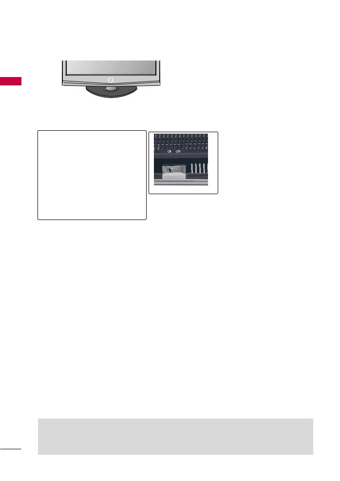
ON OFF
For 32/42LF20FR
AC power control switch (Except 19/22LH20R)
Power/Standby Indicator
Illuminates red in standby mode.
Illuminates blue when the TV is switched on.
Remote Control Sensor
POWER Button
 CHANNEL
Buttons
+
 VOLUME
-Buttons
ENTER
ENTER Button
MENU
MENU Button
INPUT
 INPUT Button
10
■ Image shown may differ from your TV.
For 42/47/55LH50YR
CHANNEL
CH
 VOLUME
Buttons
VOL
Remote Control
Sensor
Intelligent Sensor
according to the surrounding conditions.
Power/Standby Indicator
Illuminates red in standby mode. Illuminates blue when the TV is switched on.
|
ENTER Button |
|
ENTER |
|
MENU Button |
|
MENU |
|
INPUT Button |
|
INPUT |
OFF ON |
POWER Button |
AC power control |
|
switch |
|
For 19LU50R, 22LU50FR, 26LU50FR
19LU50R, 22LU50FR |
MENU Button |
|
|
|
ENTER Button |
|
|
||
INPUT Button |
|
|
||
|
VOLUME |
CHANNEL |
||
|
|
|||
POWER Button |
|
(-, +) Buttons ( , |
) Buttons |
|
INPUT |
MENU ENTER |
VOL |
CH |
|
|
|
26LU50FR |
|
|
|
|
|
|
CHANNEL ( , ) |
|
|
|
CH |
Buttons |
|
|
|
VOL |
VOLUME (+, -) |
|
|
|
Buttons |
|
|
|
|
|
|
|
ENTER Button |
|
ENTER |
SPEAKER |
MENU Button |
MENU |
|
|
Button |
|
Button |
Remote Control Sensor |
|
Power/Standby Indicator |
|
Illuminates red in standby mode. |
control |
|
Illuminates white when the TV is switched on.
PREPARATION
11
PREPARATION
■ Image shown may differ from your TV.
For 32/42/47LH70YR
PREPARATION
Remote Control Sensor,
Intelligent Sensor
Adjusts picture according to the surrounding conditions.
Moving LED
POWER Button (Touch Sensor) ,
Power/Standby Indicator
Illuminates red in standby mode.
Illuminates white when the TV is switched on.
For 42/47LH90QR
SPEAKER
Remote Control Sensor,
Intelligent Sensor
Adjusts picture according to the surrounding conditions
Power/Standby Indicator
Illuminates red in standby mode.
Illuminates white when the TV is switched on.
(Can be adjusted using the Power Indicator in the OPTION menu. G p.92)
CH
CHANNEL Buttons
VOL
VOLUME
Buttons
 ENTER Button
ENTER
MENU Button
MENU
INPUT Button
INPUT
 CAUTION
G When the TV cannot be turned on with the remote control, press the AC power control switch button on the TV.(The remote control will not work when the AC power control switch is switched off.)
12
BACK PANEL INFORMATION
■ Image shown may differ from your TV.
For 19/22LH20R
2 |
|
3 |
|
8 |
|
|
|
|
|
RS- |
IN |
|
|
|
|
|
|
(CONTROL) |
|
USB IN |
|
|
|
|
|
|
|
|
|
|
|
|
|
|
|
|
SERVICE ONLY |
|
|
HDMI/DVI IN |
RGB IN (PC) |
|
AUDIO IN |
|
|
||
|
|
|
|
|
|
4 |
|
|
|
|
|
|
(RGB/DVI) |
|
|
|
|
|
|
|
|
IN |
ANTENNA IN |
|
|
|
|
VIDEO |
L(MONO) AUDIO |
|
|
|
|
|
|
R |
|
||
|
VIDEO |
AUDIO |
|
|
|
|
|
|
COMPONENT IN |
|
|
|
OUT |
|
|
|
|
|
|
|
|
|
|
|
|
|
|
|
VARIABLE AUDIO OUT |
|
|
|
|
|
|
|
AV |
|
|
|
|
|
5 |
6 |
|
|
7 |
For 26/32/37/42LH20R |
|
|
|
|
|
||
2 |
|
3 |
|
|
|
|
|
|
|
RS-232C IN |
USB IN |
|
8 |
||
|
|
SERVICE ONLY |
|
||||
|
|
|
|
||||
|
|
(CONTROL) |
|
|
|
|
|
HDMI |
2 |
|
|
|
|
|
|
HDMI |
|
RGB IN (PC) |
|
AUDIO IN |
|
4 |
|
1 |
|
|
|
(RGB/DVI) |
|
||
|
|
|
|
|
|||
/DVI IN |
|
|
|
|
|
|
|
|
|
|
|
VIDEO |
L(MONO) AUDIO |
IN |
|
|
|
|
|
R |
|
||
|
VIDEO |
AUDIO |
|
|
|
|
|
|
COMPONENT IN |
|
|
|
OUT |
ANTENNA |
|
|
|
|
|
|
|
||
|
|
|
|
|
|
IN |
|
|
|
|
|
|
VARIABLE AUDIO OUT |
|
|
|
|
|
|
|
AV |
|
|
5 |
|
|
|
6 |
|
|
|
For 32/42LF20FR |
|
|
|
|
|
|
|
2 |
|
3 |
|
|
|
|
|
|
|
RS-232C IN |
USB IN |
|
|
8 |
|
|
|
SERVICE ONLY |
|
|
|||
|
|
(CONTROL) |
|
|
|
|
|
|
/DVI IN |
|
|
|
|
|
4 |
|
|
|
|
AUDIO IN |
|
||
|
|
|
|
|
|
||
|
|
|
|
(RGB/DVI) |
|
|
|
|
|
|
|
|
IN 1 |
|
|
|
VIDEO |
AUDIO |
VIDEO L(MONO) AUDIO R |
|
|
||
|
|
|
|
|
|||
|
COMPONENT IN |
|
|
OUT |
ANTENNA |
||
|
|
|
|
|
|
|
|
|
|
|
|
VARIABLE AUDIO OUT |
|
IN |
|
|
|
|
|
|
AV |
|
|
5 |
|
|
|
6 |
|
7 |
|
PREPARATION
2 |
2 |
|
IN |
||
|
6
AV IN2
13

PREPARATION
■ Image shown may differ from your TV.
For 32/37/42/47LH30FR
PREPARATION |
2 |
|
3 |
1 |
|
|
|
|
|
|
|
|
|||
|
|
|
|
|
|
|
|
|
|
|
RS-232C IN |
|
|
|
|
|
|
|
(CONTROL) |
|
|
|
|
|
|
2 |
|
|
|
|
|
|
|
|
RGB IN (PC) |
AUDIO IN |
|
|
|
|
|
|
(RGB/DVI) |
|
|
|
|
|
/DVI IN |
1 |
|
|
|
4 |
|
|
|
|
|
VIDEO |
L(MONO) |
AUDIO |
R |
|
|
|
|
|
|
|
1 IN AV |
VIDEO |
AUDIO |
|
|
COMPONENT IN |
|
|
|
|
VARIABLE AUDIO OUT |
|
ANTENNA |
|
AV OUT |
|
IN |
5 |
|
6 |
7 |
For 19LU50R, 22LU50FR
|
2 |
3 |
VID 8 |
L(MONO) AUDIO R |
|
|
|
|
RS-232C IN |
USB IN |
|
|
|
|
|
SERVICE ONLY |
|
|
||
|
|
(CONTROL) |
|
|
||
|
|
|
|
|
|
|
HDMI/DVI IN |
|
|
|
|
|
|
2 |
|
RGB IN (PC) |
VARIABLE AUDIO OUT |
|
|
|
|
|
|
AUDIO IN |
|
|
|
1(DVI) |
|
|
|
|
4 |
|
|
|
|
|
(RGB/DVI) |
|
|
|
|
|
EO |
L(MONO) AUDIO |
|
IN AV |
|
|
|
|
|
|
|
VIDEO |
|
AUDIO |
|
|
|
|
COMPONENT IN |
|
|
|
|
||
|
|
|
|
VARIABLE AUDIO |
T |
ANTENNA |
|
|
|
|
AV OUT |
|
|
|
|
|
|
|
IN |
|
|
|
5 |
|
|
6 |
7 |
For 26LU50FR |
2 |
3 |
8 |
|
|
|
|
|
RS-232C IN |
USB IN |
|
|
|
|
|
SERVICE ONLY |
|
|
||
|
|
(CONTROL) |
|
|
||
|
|
|
|
|
|
|
HDMI/DVI IN |
|
|
|
|
|
|
2 |
|
RGB IN (PC) |
|
AUDIO IN |
|
|
|
|
|
|
|
||
|
|
|
|
|
|
|
1(DVI) |
|
|
|
(RGB/DVI) |
|
4 |
|
|
|
EO |
L(MONO) AUDIO |
R |
1 IN AV |
|
|
|
|
|
|
|
VIDEO |
|
AUDIO |
|
|
|
|
COMPONENT IN |
|
|
|
|
||
|
|
|
|
VARIABLE AUDIO OU |
ANTENNA |
|
|
|
|
|
AV OUT |
|
|
|
|
|
|
|
IN |
|
|
|
5 |
|
|
6 |
7 |
8
3 |
2 |
|
IN |
||
|
6
AV IN2
3 |
2 |
IN |
|
6
AV IN2
14
■ Image shown may differ from your TV.
For 32/42/47LH70YR
8
3 |
2 |
1(DVI) |
1 |
4 |
6 |
RGB IN
(RGB/DVI) |
VIDEO |
L/MONO AUDIO |
R |
RS-232C IN |
|
(CONTROL) |
|||||
|
|
|
|
5 |
|
VIDEO |
AUDIO |
|
|
|
|
|
|
|
|
|
|
|
|
|
|
COMPONENTIN |
2 |
|
|
|
|
OUT AV 1 INAV |
|
|
1 |
|
|
VARIABLE AUDIO OUT |
|
|
|||
|
|
|
ANTENNA IN |
|
||||
|
|
|
|
|
|
|
|
|
|
|
|
|
|
|
|
|
8 |
For 42/47/55LH50YR, 42/47LH90QR |
|
|
|
|
||||
2 |
|
|
RS-232C IN |
|
|
|
|
|
|
|
|
|
|
|
|
|
|
|
|
|
(CONTROL) |
|
|
3 |
3 |
2 |
|
|
/DVI IN |
|
|
IN |
|||
|
|
|
|
|
|
|
||
|
|
|
|
|
|
|
|
|
|
2 |
|
RGB IN (PC) |
AUDIO IN |
|
|
|
|
|
|
(RGB/DVI) |
|
|
|
|
||
|
|
|
|
|
|
|
||
1(DVI) |
|
|
|
|
|
|
|
|
|
|
|
|
VIDEO L(MONO) AUDIO |
R |
6 |
|
|
|
|
|
|
AV |
|
6 |
||
2 |
|
|
|
|
|
|
||
|
|
|
|
|
1 IN |
|
|
|
|
|
|
|
|
|
|
|
|
1 |
|
|
|
|
|
7 |
|
|
|
|
|
|
|
|
|
|
|
|
VIDEO |
AUDIO |
VARIABLE AUDIO OUT |
ANTENNA |
|
AV OUT |
|||
5 |
COMPONENT IN |
|
IN |
|
|
|
|
|
AV IN2 |
1 |
|
|
|
6 |
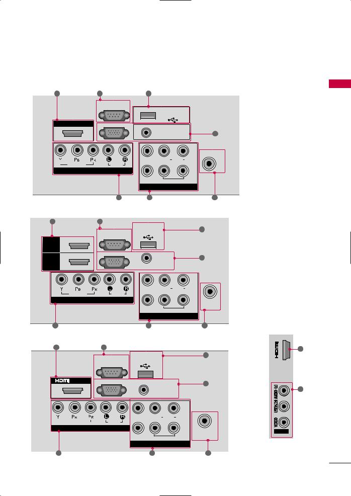
For operation with AC power.
Caution: Never attempt to operate the TV on DC power.
HDMI/DVI IN, HDMI IN
2Digital Connection.
Supports HD video and Digital audio. Doesn’t support 480i/576i.
Accepts DVI video using an adapter or HDMI to DVI cable (not included).
3Used by third party devices.
RGB IN RGB IN(PC)
Analog PC Connection. Uses a D-sub 15 pin cable (VGA cable).
AUDIO IN (RGB/DVI)
1/8"(0.32cm)headphone jack for analog PC audio input.
COMPONENT IN
5
Supports HD.
Analog composite connection. Supports standard definition video only (480i).
AV Output
Connect second TV or monitor to the AV OUT socket on the TV.
Variable Audio Output
Connect an external amplifier or add a subwoofer to your surround sound system.
ANTENNA IN
Connect over-the air signals to this jack. Connect cable signals to this jack.
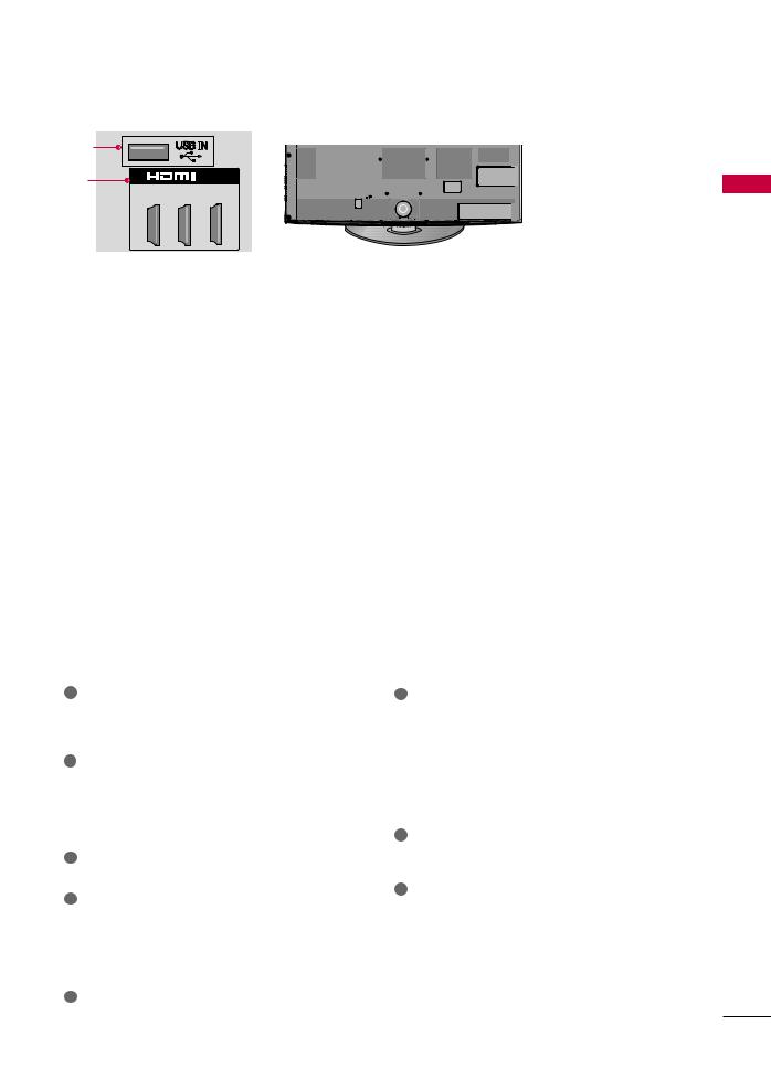
8USB IN
(For 32/37/42/47LH30FR, 42/47/55LH50YR, 32/42/47LH70YR, 42/47LH90QR)
Used for viewing photos/movies and listening to MP3.
USB IN SERVICE ONLY
(For 19/22/26/32/37/42LH20R, 32/42LF20FR, 19LU50R, 22/26LU50FR)
Used for software updates.
Uses a red, green, and blue cable for video & red and white for audio.
PREPARATION
15
PREPARATION
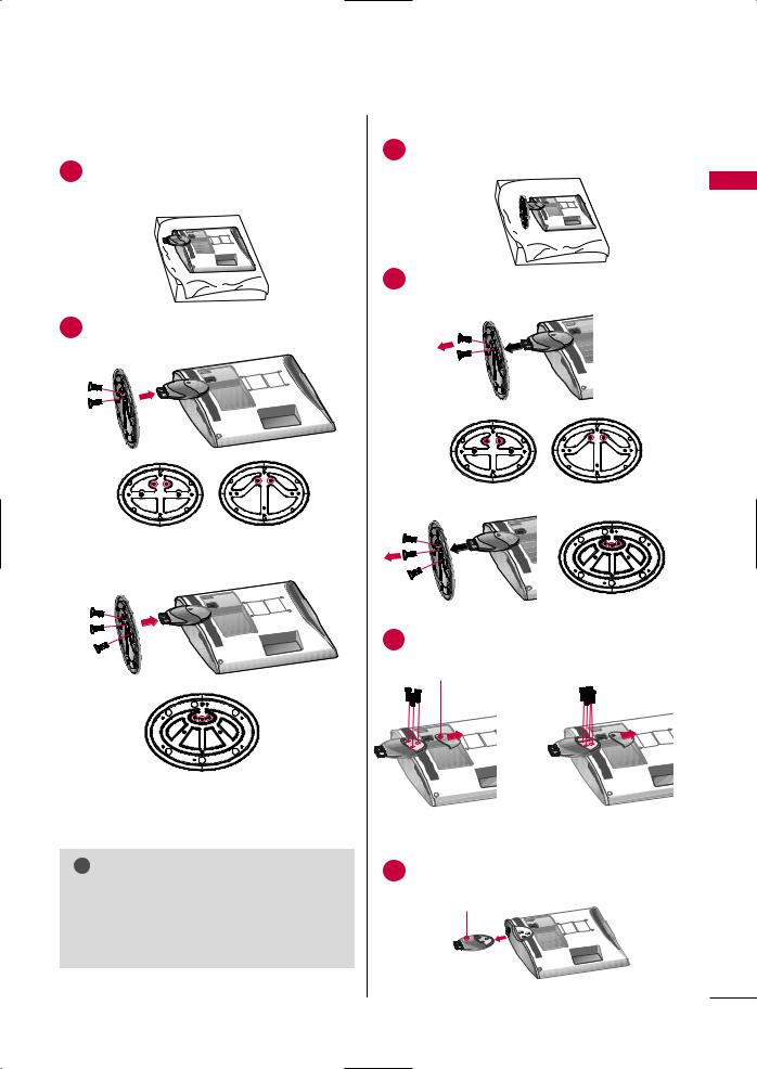
STAND INSTRUCTION
■ Image shown may differ from your TV.
PREPARATION
For 19/22LH20R
INSTALLATION
1 |
2 |
cushioned surface to protect the screen from damage.
DETACHMENT |
PROTECTION COVER |
|
1 |
place the TV screen side down on a |
4 |
|
surface to protect the screen from |
|
|
damage. |
|
|
|
PROTECTION COVER |
2 |
5 |
securely using the holes in the |
|
|
3
16
For 26/32/37/42LH20R, 32/37/42/47LH30FR, 42/47LH50YR, 42/47LH90QR
INSTALLATION |
|
DETACHMENT |
||
1 |
the TV screen side down on a |
1 |
place the TV screen side down on a |
|
surface to protect the screen from |
||||
|
to protect the screen from |
|
||
|
|
damage. |
||
damage. |
|
|
||
|
|
|
||
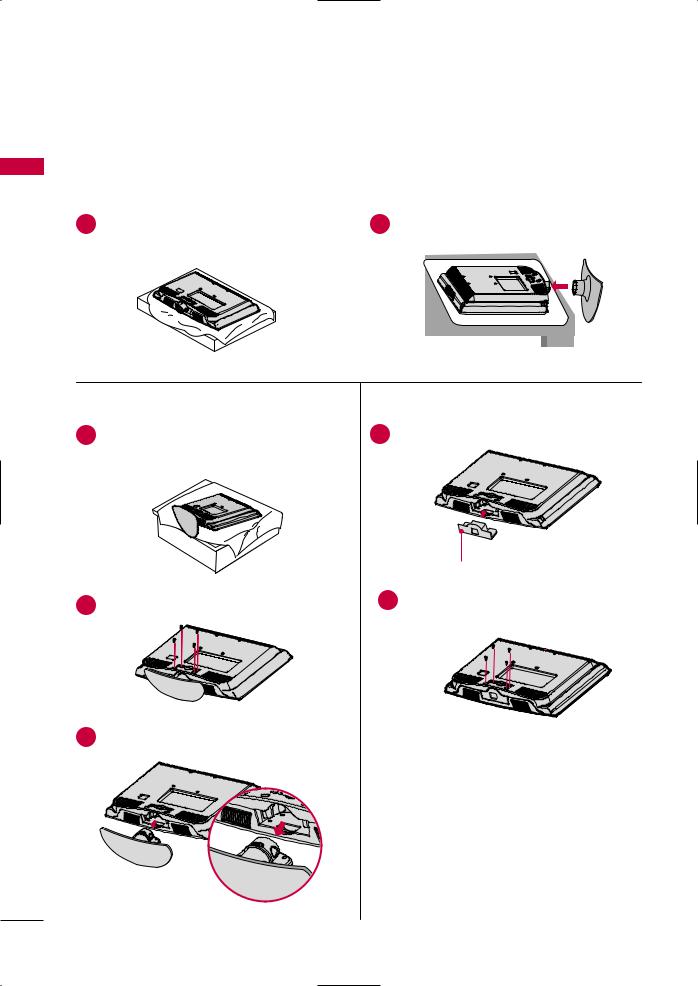
2Assemble the TV as shown.
3Fix the 4 bolts securely using the holes in the back of the TV.
! NOTE
GWhen assembling the desk type stand, make sure the bolt is fully tightened (If not tightened fully, the TV can tilt forward after the product installation). Do not over tighten.
2
3
PROTECTION COVER
For 26/32/37/42LH20R, 32/37/42/47LH30FR, 42/47/55LH50YR
After removing the stand, install the included protection cover over the hole for the stand.
Press the PROTECTION COVER into the TV until you hear it click.
For 42/47LH90QR
Insert the PROTECTION COVER into the TV. After removing the protection paper from the protection cover, adhere it to the TV as shown.
PREPARATION
17
PREPARATION
For 32/42LF20FR
INSTALLATION
|
1 Carefully place |
TV screen side down on a |
|
cushioned surface to protect the screen from |
|
PREPARATION |
damage. |
|
|
|
|
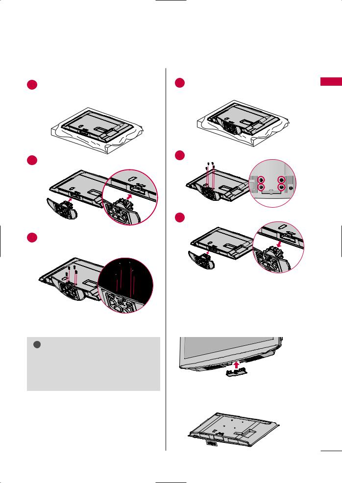
2Assemble the STAND BODY to the STAND BASE with the included screws.
DETACHMENT
1place the TV
surface to
damage.
2
3Assemble the TV
4 |
Fix the 4 bolts |
securely using the holes in the |
back of the TV. |
|
PROTECTION COVER
After removing the stand, install the included protection cover over the hole for the stand.
Press the PROTECTION COVER into the TV until you hear it click.
18
For 19LU50R, 22/26LU50FR
INSTALLATION
1 down on a screen from
damage.
2 |
Fix the bolts securely using the holes. |
19LU50R, 22LU50FR
DETACHMENT
1place the TV screen side down on a
surface to protect the screen from
damage.
2 |
bolts and then detach the stand |
19LU50R, 22LU50FR
26"
26LU50FR
26LU50FR
3
And detach the COVER BASE from the TV.
COVER BASE
! NOTE
GWhen assembling the desk type stand, make sure the bolt is fully tightened (If not tightened fully, the TV can tilt forward after the product installation). Do not over tighten.
19LU50R, |
26LU50FR |
4
STAND BODY
PREPARATION
19
PREPARATION
For 32/42/47LH70YR
■ Image shown may differ from your TV.
INSTALLATION
1
PREPARATION
2
-
to the STAND
DETACHMENT
1 |
shown. |
|
2 |
32LH70YR, 42LH70YR |
47LH70YR |
|
damage. |
Stand Body |
|
M4x20 |
M4x16 |
Stand Base |
|
3
place the TV screen side down on a surface to protect the screen from
3
4 |
the |
32LH70YR
4
M4x20
5
(For 42/47LH70YR)
PROTECTIVE COVER
from the TV as shown.
STAND AR COVER
! NOTE
G When assembling the desk type stand, make sure the bolt is fully tightened (If not tightened fully, the TV can tilt forward after the product installation). Do not over tighten.
20
VESA WALL MOUNTING
Install your wall mount on a solid wall perpendicular to the floor. When attaching to other building materials, please contact your nearest installer.
If installed on a ceiling or slanted wall, it may fall and result in severe personal injury.
We recommend that you use an LG brand wall mount when mounting the TV to a wall.
LG recommends that wall mounting be performed by a qualified professional installer.
For 32/42/47LH70YR: First you connect the USB extension cable to the USB IN terminal, and then hang it on the wall.
|
VESA (A * B) |
|
|
|
|
Model |
A |
Standard Screw |
Quantity |
Wall Mount Bracket (sold separately) |
|
B |
|||||
19/22LH20R, |
100 * 100 |
M4 |
4 |
|
|
19LU50R, 22LU50FR |
|
|
|||
|
|
|
|
|
|
|
|
|
|
|
RW120 |
26LH20R, 26LU50FR |
|
|
|
|
RW230 |
|
200 * 100 |
M4 |
4 |
|
|
32LH20R, 32LF20FR, |
|
|
|
|
|
32LH30FR, 32LH70YR |
|
|
|
|
|
|
|
|
|
RW230 |
AW-47LG30M |
37/42LH20R, |
|
|
|
|
|
42LF20FR, |
|
|
|
|
|
37/42/47LH30FR |
200 * 200 |
M6 |
4 |
|
|
42/47LH50YR, |
|
|
|||
|
|
|
|
|
|
42/47LH70YR, |
|
|
|
AW-47LG30M |
|
42/47LH90QR |
|
|
|
|
|
55LH50YR |
400 * 400 |
M6 |
4 |
|
|
|
|
|
|
|
AW-55LH40M |
! NOTE
G Screw length needed depends on the wall mount used. For further information, refer to the instructions included with the mount.
GStandard dimensions for wall mount kits are shown in the table.
GWhen purchasing our wall mount kit, a detailed installation manual and all parts necessary for assembly are provided.
GDo not use screws longer then the standard dimension, as they may cause damage to the inside to the TV.
G For wall mounts that do not comply with the VESA standard screw specifications, the length of the screws may differ depending on their specifications.
GDo not use screws that do not comply with the VESA standard screw specifications.
Do not fasten the screws too tightly, this may damage the TV or cause the TV to a fall, leading to personal injury. LG is not liable for these kinds of accidents.
GLG is not liable for TV damage or personal injury when a non-VESA or non specified wall mount is used or the consumer fails to follow the TV installation instructions.
 CAUTION G Do not install your Wall Mount Bracket while your TV is turned on. It may result in personal injury due to electric shock.
PREPARATION
21
PREPARATION
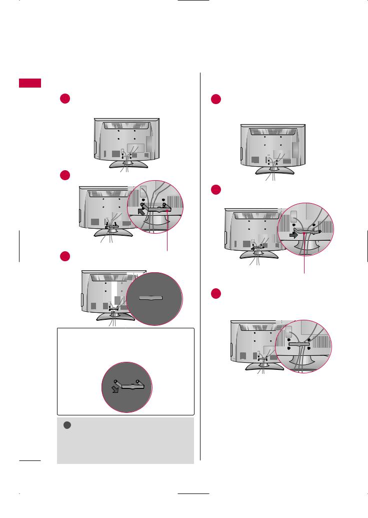
CABLE ARRANGEMENT
■ Image shown may differ from your TV.
For 19/22LH20R
PREPARATION |
1 |
|
|
|
EXTERNAL EQUIPMENT SETUP section. |
2 Install the CABLE MANAGEMENT CLIP as shown.
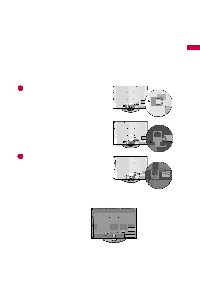
For 26/32/37/42LH20R, 32/42LF20FR, 32/37/42/47LH30FR, 42/47/55LH50YR, 42/47LH90QR
1Connect the cables as necessary.
To connect additional equipment, see the
EXTERNAL EQUIPMENT SETUP section.
2 |
|
CABLE MANAGEMENT CLIP |
3 |
CABLE MANAGEMENT |
Install the CABLE MANAGEMENT CLIP as shown.
3
How to remove the CABLE MANAGEMENT CLIP
G Hold the CABLE MANAGEMENT CLIP with both hands and pull it backward.
! NOTE
G Do not hold the CABLE MANAGEMENT CLIP when moving the TV.
-If the TV is dropped, you may be injured or the product may be broken.
CABLE MANAGEMENT CLIP
CABLE MANAGEMENT
22
For 19LU50R, 22/26LU50FR
1 After connecting the cables as necessary, install CABLE
the cables.
PREPARATION
For 32/42/47LH70YR
1 |
BLE |
|
2Connect the cables as necessary.
To connect additional equipment, see the
EXTERNAL EQUIPMENT SETUP section.
HOW TO SECURE THE POWER CABLE
SCREW
Secure
BRA vent dent.
PROTECTIVE BRACKET
23
PREPARATION
DESKTOP PEDESTAL INSTALLATION
PREPARATION
■ Image shown may differ from your TV.
For proper ventilation, allow a clearance of 4 inches on all four sides from the wall.
|
4 inches |
|
4 inches |
4 inches |
4 inches |
|
 CAUTION G Ensure adequate ventilation by following the clearance recommendations.
G Do not mount near or above any type of heat source.
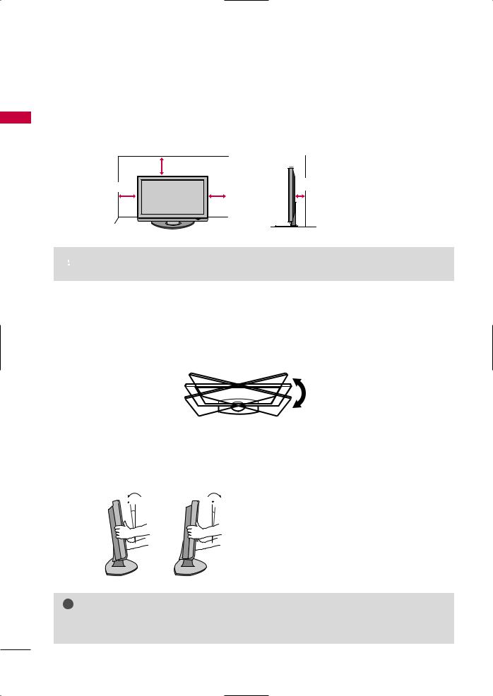
SWIVEL STAND (Except 19/22LH20R, 19LU50R, 22/26LU50FR)
After installing the TV, you can adjust the TV manually to the left or right direction by 20 degrees to suit your viewing position.
POSITIONING YOUR DISPLAY (For 19/22LH20R)
■Here shown may be somewhat different from your TV.
■Adjust the position of the panel in various ways for maximum comfort.
•Tilt range
12
0 
0 |
3 |
! NOTE
G 19LU50R, 22/26LU50FR have a fixed stand type without the tilt and swivel features so excessive pressure may damage the TV.
24
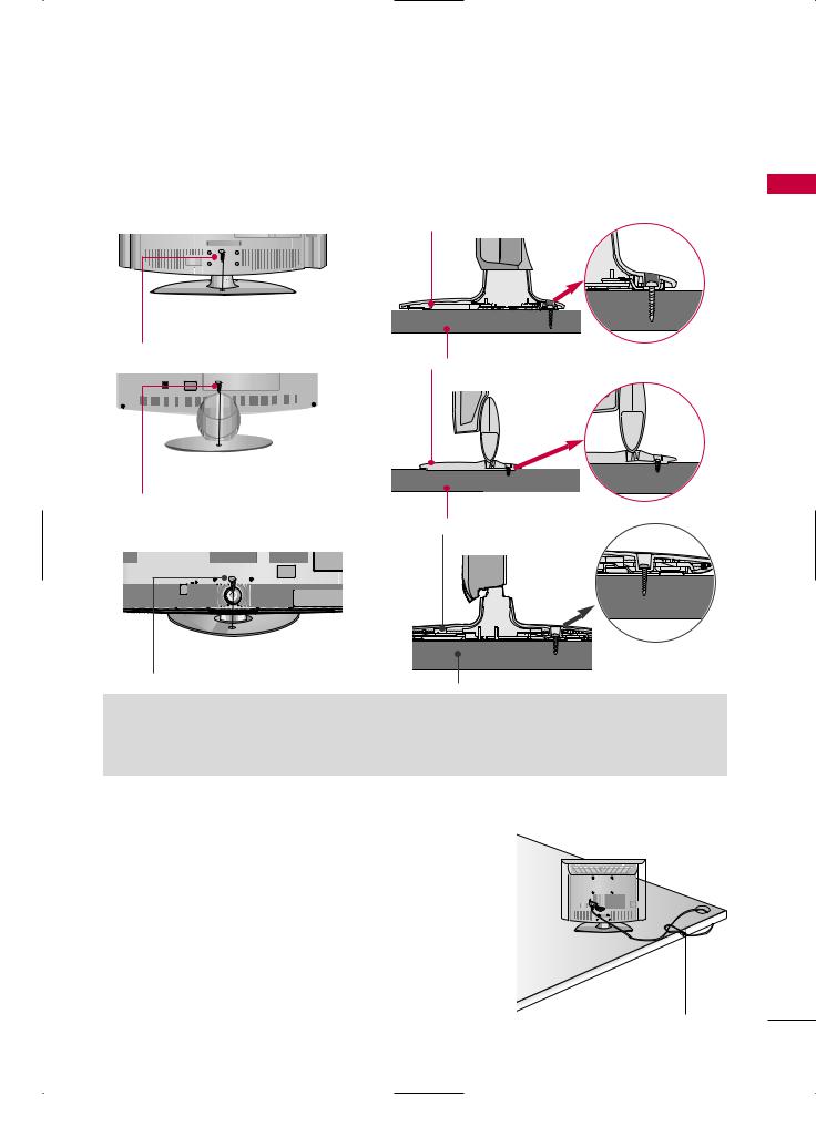
ATTACHING THE TV TO A DESK
(Except 19/22LH20R, 47LH30FR, 47/55LH50YR, 19LU50R, 22LU50FR, 42/47LH70YR, 47LH90QR)
The TV must be attached to a desk so it cannot be pulled in a forward/backward direction, potentially causing injury or damaging the product.
Stand |
1-Screw |
(provided as parts of the product) |
Desk
Stand
1-Screw
(provided as parts of the product)
Desk |
Stand |
1-Screw
(provided as parts of the product)
Desk
 WARNING
G To prevent TV falling over, the TV should be securely attached to the floor/wall per installation instructions. Tipping, shaking, or rocking the machine may cause injury.
KENSINGTON SECURITY SYSTEM
■ This feature is not |
for all models. |
|
|
|
|
|
|
|
||
- The TV is equipped |
a Kensington Security System connector on |
|
||||||||
the back panel. Connect the Kensington Security System cable as |
|
|
|
|
|
|
||||
|
|
|
|
|
|
|||||
|
|
|
|
|
|
|||||
shown below. |
|
|
|
|
|
|
|
|
|
|
- For the |
detailed installation |
and use of the |
Kensington Security |
|
|
|
|
|
|
|
|
|
|
|
|
|
|||||
System, |
refer to |
user’s |
guide provided |
with the Kensington |
|
|
|
|
|
|
|
||||||||||
|
|
|
|
|
|
|
|
|
|
|
Security System.
For further information, contact http://www.kensington.com, the internet homepage of the Kensington company. Kensington sells security systems for expensive electronic equipment such as notebook PCs and LCD .
NOTE: The Kensington Security System is an optional accessory.
PREPARATION
25
PREPARATION
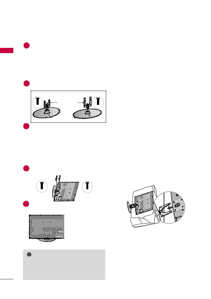
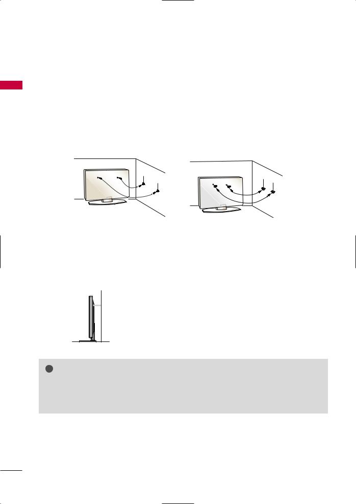
SECURING THE TV TO THE WALL TO PREVENT FALLING WHEN THE TV IS USED ON A STAND
PREPARATION
■You should purchase necessary components to prevent the TV from tipping over (when not using a wall mount).
■Image shown may differ from your TV.
We recommend that you set up the TV close to a wall so it cannot fall over if pushed backwards.
Additionally, we recommend that the TV be attached to a wall so it cannot be pulled in a forward direction, potentially causing injury or damaging the product.
Caution: Please make sure that children don’t climb on or hang from the TV.
■Insert the eye-bolts (or TV brackets and bolts) to tighten the product to the wall as shown in the picture. *If your product has the bolts in the eye-bolts position before inserting the eye-bolts, loosen the bolts.
* Insert the eye-bolts or TV brackets/bolts and tighten them securely in the upper holes.
Secure the wall brackets with the bolts (sold separately) to the wall. Match the height of the bracket that is mounted on the wall to the holes in the product.
Ensure the eye-bolts or brackets are tightened securely.
■ Use a sturdy rope (sold separately) to tie the product. It is safer to tie the rope so it becomes horizontal between the wall and the product.
! NOTE
G Use a platform or cabinet strong enough and large enough to support the size and weight of the TV. G To use the TV safely, make sure that the height of the bracket on the wall and the one on the TV are
the same.
26
■To prevent damage do not connect to the power outlet until all connections are made between the devices.
■Image shown may differ from your TV.
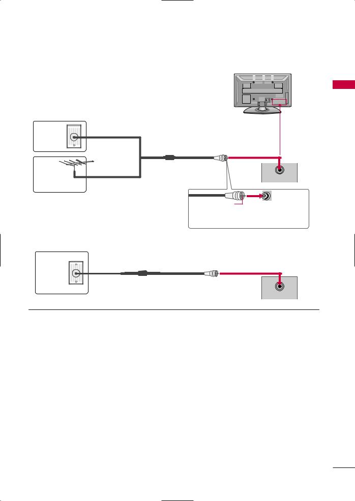
ANTENNA OR CABLE CONNECTION
1. Antenna (Analog)
Wall Antenna Socket or Outdoor Antenna without a Cable Box
Connection.
For optimum picture quality, adjust antenna direction if needed.
Multi-family Dwellings/Apartments
Wall  (Connect to wall antenna socket)
Antenna
Socket
Outdoor |
RF Coaxial Wire (75 ohm) |
Antenna |
ANTENNA |
(VHF, UHF) |
IN |
Single-family Dwellings /Houses |
|
|
(Connect to wall jack for outdoor |
|
antenna) |
Copper Wire
Be careful not to bend the copper wire when connecting the antenna.
2. Cable
Cable TV
Wall Jack
RF Coaxial Wire (75 ohm)
ANTENNA
IN
■To improve the picture quality in a poor signal area, please purchase a signal amplifier and install properly.
■If the antenna needs to be split for two TV’s, install a 2-Way Signal Splitter.
■If the antenna is not installed properly, contact your dealer for assistance.
PREPARATION
27
EXTERNAL EQUIPMENT SETUP
SETUP EQUIPMENT EXTERNAL
■To prevent the equipment damage, never plug in any power cords until you have finished connecting all equipment.
■This part of EXTERNAL EQUIPMENT SETUP mainly use picture for 26/32/37/42LH20R.
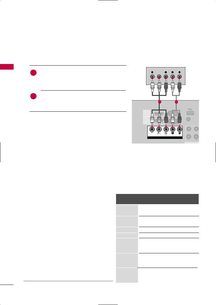
HD RECEIVER SETUP
Component Connection
1. How to connect
1Connect the video outputs (Y, PB, PR) of the digital settop box to the COMPONENT IN VIDEO* or COM-
PONENT IN VIDEO 1*/2* jacks on the TV. Match the jack colors (Y = green, PB = blue, and PR = red).
Connect the audio output of the digital set-top box to the COMPONENT IN AUDIO* or COMPONENT IN AUDIO 1*/2* jacks on the TV.
*COMPONENT IN VIDEO/AUDIO
:For 19/22/26/32/37/42LH20R, 32/42LF20FR, 32/37/42/47LH30FR, 19LU50R, 22/26LU50FR
*COMPONENT IN VIDEO 1/AUDIO 1, COMPONENT IN VIDEO 2/AUDIO 2
:For 42/47/55LH50YR, 32/42/47LH70YR, 42/47LH90QR
Y  PR L R
12
|
|
USB IN |
|
RS-232C IN |
SERVICE ONLY |
|
(CONTROL) |
|
HDMI |
|
|
HDMI |
(PC) |
AUDIO IN |
|
(RGB/DVI |
|
/DVI IN |
|
|
|
|
VIDEO L(MONO |
VIDEO |
AUDIO |
|
COMPONENT IN |
|
|
|
|
VARIABLE |
|
|
A |
2. How to use
■Turn on the digital set-top box.
(Refer to the owner’s manual for the digital set-top box operation.)
■Select the Component* or Component1*/2* input source on the TV using the INPUT button on the remote control.
* Component: For 19/22/26/32/37/42LH20R, |
Y, CB/PB, CR/PR |
|
|
32/42LF20FR, 32/37/42/47LH30FR, |
|
19LU50R, 22/26LU50FR |
Resolution |
* Component1/2: For 42/47/55LH50YR, |
|
32/42/47LH70YR, 42/47LH90QR |
720x480i |
Horizontal Vertical
Frequency(KHz) Frequency(Hz)
15.7359.94
15.7560.00
|
|
|
|
720x480p |
31.47 |
59.94 |
|
|
|
|
31.50 |
60.00 |
|
|
|
|
|
|
||
Supported Resolutions |
|
|
720x576i |
15.625 |
50.00 |
|
|
|
720x576p |
31.25 |
50.00 |
||
|
|
|
|
|||
|
|
|
|
|
44.96 |
59.94 |
Signal |
Component |
HDMI |
|
1280x720p |
||
|
45.00 |
60.00 |
||||
|
|
|
|
|||
|
|
|
|
|
||
|
Yes |
No |
|
|
37.50 |
50.00 |
480i |
|
|
||||
|
|
|
|
|||
480p |
Yes |
Yes |
|
|
28.125 |
50.00 |
720p |
Yes |
Yes |
|
1920x1080i |
33.72 |
59.94 |
|
|
33.75 |
60.00 |
|||
|
|
|
|
|
||
1080i |
Yes |
Yes |
|
|
56.25 |
50.00 |
|
|
|
|
|
||
1080p |
Yes (50/60Hz only) |
Yes (24/30/50/60Hz) 1920x1080p |
67.432 |
59.94 |
||
|
|
|
|
|
67.50 |
60.00 |
|
|
|
|
|
||
|
|
|
|
|
|
|
28
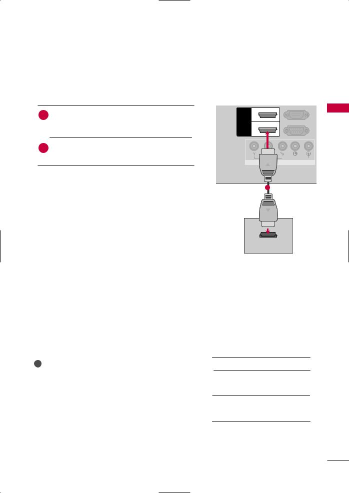
HDMI Connection |
|
|
|
1. How to connect |
|
|
|
|
|
(CONTROL) |
|
1 Connect the digital set-top box to the HDMI/DVI IN*, |
HDMI |
2 |
|
HDMI/DVI IN 1* or HDMI/DVI IN 1(DVI)*, HDMI |
HDMI |
RGB IN (PC) |
|
2* or HDMI IN 2*/3* jack on the TV. |
1 |
||
/DVI IN |
|||
connection is necessary. |
|
|
|
HDMI supports both audio and video. |
|
AUDIO |
|
|
|
||
|
|
COMPONENT IN |
|
* HDMI/DVI IN: For 19/22LH20R |
|
|
|
* HDMI/DVI IN 1, HDMI 2: For 26/32/37/42LH20R, |
|
|
|
32/37/42/47LH30FR, 19LU50R, |
|
1 |
|
22/26LU50FR |
|
|
|
* HDMI/DVI IN 1, HDMI IN 2: For 32/42LF20FR |
|
|
|
* HDMI IN 3: For 32/37/42/47LH30FR, 26LU50FR |
|
|
|
* HDMI/DVI IN 1(DVI), HDMI IN 2/3: For 42/47/55LH50YR, |
|
|
|
32/42/47LH70YR, 42/47LH90QR |
|
|
|
2. How to use |
|
HDMI OUTPUT |
|
|
|
■Turn on the digital set-top box.
(Refer to the owner’s manual for the digital set-top box.)
■Select the HDMI* or HDMI1*/2*/3* input source on the TV using the INPUT button on the remote control.
* HDMI: For 19/22LH20R
*HDMI1/2: Except 19/22LH20R
*HDMI3: For 32/37/42/47LH30FR, 26LU50FR, 42/47/55LH50YR,
32/42/47LH70YR, 42/47LH90QR
|
|
HDMI-DTV mode |
|
|
|
|
|
|
|
|
|
Resolution |
Horizontal |
Vertical |
|
|
Frequency(kHz) |
Frequency(Hz) |
|
|
|
|
||
|
|
|
31.47 |
59.94 |
|
|
720x480 |
||
|
|
31.50 |
60.00 |
|
|
|
|
||
! NOTE |
|
720x576 |
31.25 |
50.00 |
G Check HDMI cable over version 1.3. |
|
|
44.96 |
59.94 |
If the HDMI cables don’t support HDMI version |
|
1280x720 |
||
|
45.00 |
60.00 |
||
1.3, it can cause flickers or no screen display. In |
|
|
37.50 |
50.00 |
this case use the latest cables that support |
|
|
33.72 |
59.94 |
HDMI version 1.3. |
|
1920x1080i |
||
|
33.75 |
60.00 |
||
|
|
|||
G HDMI mode supports PCM audio format only. |
|
|
28.125 |
50.00 |
G If the Audio setting is set to Dolby/DTS/Bitstream |
|
|
67.432 |
59.94 |
in some DVDP/STB, make sure to change the set- |
|
1920x1080p |
67.50 |
60.00 |
ting to PCM. |
|
56.25 |
50.00 |
|
|
|
|||
|
|
|
27.00 |
24.00 |
|
|
|
33.75 |
30.00 |
|
|
|
|
|
SETUP EQUIPMENT EXTERNAL
29
EXTERNAL EQUIPMENT SETUP
SETUP EQUIPMENT EXTERNAL
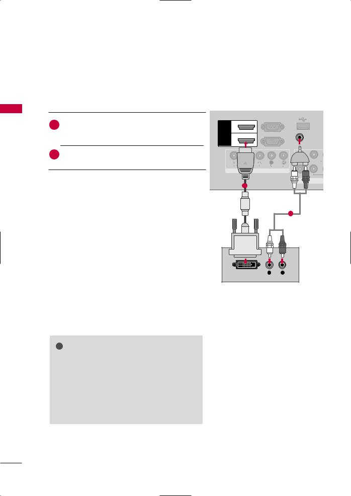
DVI to HDMI Connection
1. How to connect
Connect the DVI output of the digital set-top box to the
1HDMI/DVI IN*, HDMI/DVI IN 1*, or HDMI/DVI IN 1(DVI)* jack on the TV.
output to the
*HDMI/DVI IN: For 19/22LH20R
*HDMI/DVI IN 1: For 26/32/37/42LH20R, 32/42LF20FR,
32/37/42/47LH30FR, 19LU50R, 22/26LU50FR
* HDMI/DVI IN 1(DVI): For 42/47/55LH50YR, 32/42/47LH70YR, 42/47LH90QR
2.to use
on the digital set-top box.
to the owner’s manual for the digital set-top box.)
the HDMI*, or HDMI1* input source on the TV the INPUT button on the remote control.
*HDMI: For 19/22LH20R
*HDMI1: Except 19/22LH20R
|
|
USB IN |
|
|
RS-232C IN |
SERVICE ONLY |
|
|
(CONTROL) |
|
|
HDMI 2 |
|
||
HDMI |
RGB IN (PC) |
AUDIO IN |
|
1 |
(RGB/DVI) |
||
/DVI IN |
|||
|
|
||
|
|
L(MONO) A |
|
|
AUDIO |
|
|
|
COMPONENT IN |
|
|
|
|
RIABLE AUD |
|
|
|
AV |
|
1
2
DVI OUTPUT |
L |
R |
AUDIO
! NOTE
G A DVI to HDMI cable or adapter is required for this connection. DVI doesn't support audio, so a separate audio connection is necessary.
G HDMI mode supports PCM audio format only.
GIf the Audio setting is set to Dolby/DTS/Bitstream in some DVDP/STB, make sure to change the setting to PCM.
30
 Loading...