


LG 428, 376, 42PG6, 50PG7, 426 User Manual
...ENGLISH
LCD TV PLASMA TV OWNER’S MANUAL
LCD TV MODELS PLASMA TV MODELS
32LG6*** 50PG3***
37LG6*** 42PG6***
42LG6*** 50PG6***
47LG6*** 60PG6***
42LG7*** 50PG7***
47LG7*** 60PG7***
52LG7***
32LG8***
42LG8***
Please read this manual carefully before operating your set. Retain it for future reference.
Record model number and serial number of the set. Refer to the label on the back cover and quote this information.
To your dealer when requiring service.
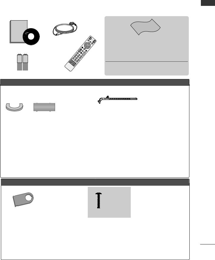
ACCESSORIES
Ensure that the following accessories are included with your TV.
If an accessory is missing, please contact the dealer where you purchased the product.
■ Image shown may differ from your TV.
Owner's
Manual
Owner’s manual
Owner’s Manual
Power Cord
|
|
|
|
1 |
MUTE |
|
|
|
|
4 |
2 |
|
|
|
7 |
5 |
3 |
|
|
LIST |
|
8 |
6 |
|
|
|
0 |
9 |
|
TI |
|
|
Q. |
|
|
|
ME |
|
|
|
|
INDEX |
S |
|
VIEW |
|
|
|
IZE |
|
|
|
|
|
H |
U |
|
|
|
|
OLD |
PDATE |
REVEAL |
|
|
|
|
EXT |
|
|
|
|
|
T |
|
|
|
|
|
PIP |
|
|
|
RETU RN
F
AV
P
Q. STB |
TV |
WE |
MENU |
PO |
|
ENU |
R |
|
|
INPUT |
|
M |
|
|
|
|
DVD |
OK
AV
MODE
Polishing Cloth
Polishing cloth for use on the screen
This feature is not available for all models.
*Lightly wipe any stains or fingerprints on the surface of the TV with the polishing cloth.
Do not use excessive force. This may cause scratching or discolouration.
Batteries |
Remote Control |
PLASMA TV models
Cable management clip |
Cable Holder |
|
(except |
(only 50/60PG6***, (only 50PG3***) |
|
50PG3***) |
50/60PG7 ) |
|
|
*** |
|
|
|
42PG6***: 1EA |
|
|
50PG3***: 2EA only |
|
protection cover |
Only 50PG3***, |
|
(Refer to p.10) |
50/60PG7*** |
or
Ferrite Core
Only 50PG3***, 50/60PG7***
Use of ferrite core
Ferrite core can be used to reduce the electromagnetic wave when connecting the power cord.
The closer the location of the ferrite core to the power plug, the better it is.
LCD TV models
(only 42PG6***)
4-bolts for stand assembly Refer to p. 10
power plug closely.
Only 32/37/42/47/52LG6***
Cable management clip |
|
|
|
|
Protection cover |
||||
(Refer to p.15) |
(Refer to p.12) |
|||
Only 42/47/52LG7***, 32/42LG8***
(42LG7***, 32/42LG8*** only)
x 4 |
or |
x 4 |
(only 32/37LG6***) |
(only 42LG6***) |
32LG6***: 3EA 4EA 2EA 1EA 4EA 37LG6***: 4EA
bolts for stand assembly (Refer to p. 11)
(32/42LG8*** only)
Bolts for stand assembly |
Protection cover |
1-screw for stand fixing |
(Refer to p.12) |
(Refer to p.12) |
(Refer to p.9) |
ACCESSORIES
1

CONTENTS
|
ACCESSORIES..................................................... |
1 |
CONTENTS |
|
|
|
PREPARATION |
|
|
Front Panel Controls................................................. |
4 |
|
Back Panel Information ............................................ |
7 |
|
Attaching the TV to a desk ..................................... |
9 |
|
Stand Installation..................................................... |
10 |
|
Back Cover for Wire Arrangement....................... |
13 |
|
Please set it up carefully so the product |
|
|
does not fall over. ..................................................... |
16 |
|
Desktop Pedestal Installation ............................... |
17 |
|
Wall Mount: Horizontal installation..................... |
17 |
|
Antenna Connection............................................... |
18 |
|
EXTERNAL EQUIPMENT SETUP |
|
|
HD Receiver Setup ....................................................... |
19 |
|
DVD Setup .................................................................... |
22 |
|
VCR Setup..................................................................... |
25 |
|
Other A/V Source Setup .......................................... |
28 |
|
External Stereo............................................................. |
29 |
|
AV Output Setup ........................................................ |
30 |
|
PC Setup ......................................................................... |
31 |
|
- Screen Setup for PC Mode................................ |
34 |
WATCHING TV / PROGRAMME CONTROL
Remote Control Key Functions.................................. |
38 |
Turning on the TV....................................................... |
40 |
Programme Selection ................................................. |
40 |
Volume Adjustment...................................................... |
40 |
Quick Menu................................................................... |
41 |
On Screen Menus Selection and Adjustment ...... |
42 |
Auto Programme Tuning............................................ |
43 |
Manual Programme Tuning....................................... |
44 |
Fine Tuning ..................................................................... |
45 |
Assigning a Station Name.......................................... |
46 |
Booster............................................................................ |
47 |
Programme Edit ........................................................... |
48 |
Favourite Programme .................................................. |
49 |
Selecting the Programme List.................................. |
50 |
.................................................................. |
51 |
Key lock.......................................................................... |
53 |
AV Mode......................................................................... |
54 |
TO USE THE USB DEVICE |
|
When connecting the USB device........................... |
55 |
Photo List........................................................................ |
56 |
Music List........................................................................ |
58 |
Movie List ......................................................................... |
60 |
Divx Registration Code ................................................... |
62 |
PICTURE CONTROL |
|
Watching PIP(Picture-in-Picture) ............................. |
63 |
Picture Size (Aspect Ratio)Control......................... |
64 |
Preset Picture Settings |
|
- Picture Mode-Preset............................................ |
66 |
- Auto Colour Tone Control(Cool/Medium/Warm)67 |
|
Manual Picture Adjustment |
|
- Picture Mode-User Option................................ |
68 |
- Colour Tone - User Option............................... |
69 |
- Picture Improvement Technology................... |
70 |
Advanced - Gamma...................................................... |
71 |
Advanced - Film Mode/Real Cinema....................... |
72 |
Advanced - Black(Darkness) Level........................... |
73 |
Eye Care .......................................................................... |
74 |
Advanced-TruMotion ................................................... |
75 |
Picture Reset.................................................................. |
76 |
TruMotion Demo .......................................................... |
77 |
Power Indicator.............................................................. |
78 |
Image Sticking Minimization(ISM) Method........... |
79 |
Power Saving Picture Mode ....................................... |
80 |
Factory Reset ................................................................. |
81 |
2

SOUND & LANGUAGE CONTROL |
|
Auto Volume Leveler .................................................... |
82 |
Preset Sound Settings - Sound Mode .................... |
83 |
Sound Setting Adjustment - User Mode ............... |
84 |
Balance ............................................................................ |
85 |
TV Speakers On/Off Setup ....................................... |
86 |
Selecting Audio Out.................................................... |
86 |
Sliding Mode.................................................................. |
87 |
I/II |
|
- Stereo/Dual Reception....................................... |
88 |
- NICAM Reception ....................................................... |
89 |
- Speaker Sound Output Selection.................... |
89 |
On-Screen Menu Language Selection ...................... |
90 |
TIME SETTING |
|
Clock Setup.................................................................... |
91 |
Auto On/Off Timer Setting ....................................... |
92 |
Sleep Timer Setting...................................................... |
93 |
Auto Shut-off Setting .................................................. |
94 |
TELETEXT |
|
Switch On/Off ............................................................. |
95 |
SIMPLE Text.................................................................... |
95 |
TOP Text ......................................................................... |
96 |
FASTEXT ......................................................................... |
96 |
Special Teletext Functions.......................................... |
97 |
APPENDIX |
|
Troubleshooting............................................................ |
98 |
Maintenance ............................................................... |
100 |
Product Specifications .............................................. |
101 |
Programming the Remote Control ...................... |
103 |
IR Codes ..................................................................... |
105 |
External Control Through RS-232C ................... |
107 |
CONTENTS
3
PREPARATION
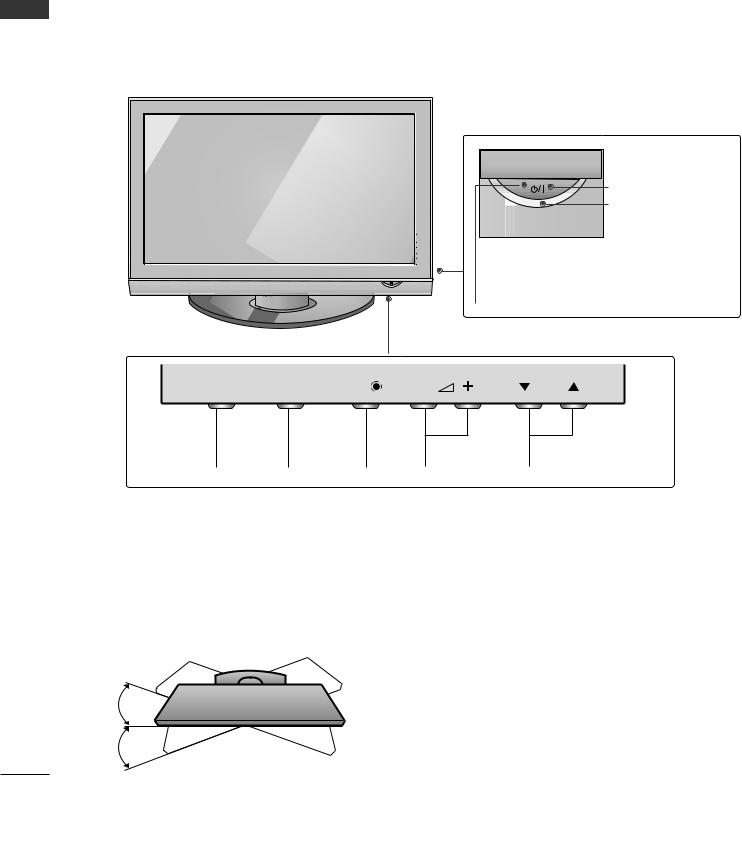
FRONT PANEL CONTROLS
PREPARATION
■This is a simplified representation of the front panel. Image shown may differ from your TV.
■If your product has a protection film attached, remove the film and then wipe the product with a polishing cloth.
Plasma TV Models
Remote Control Sensor
POWER
Power/Standby Indicator
• illuminates red in standby mode.
• illuminates green when the TV is switched on.
INPUT |
MENU |
OK |
|
P |
|
INPUT |
MENU |
OK |
VOLUME |
PROGRAMME |
Swivel Stand
This feature is not available for all models.
After installing the TV, you can adjust the TV set manually to the left or right direction by 20 degrees to suit your viewing position.
4
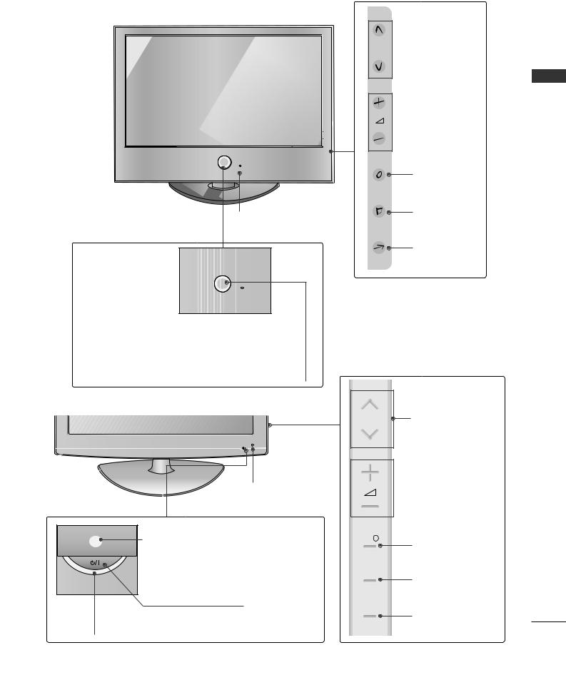
LCD TV Models
32/37/42/47LG6***
 PROGRAMME
P
 VOLUME
OK
OK
Intelligent Sensor
Adjusts picture according to the surrounding conditions
POWER
Remote Control Sensor
Power/Standby Indicator
•illuminates red in standby mode.
•illuminates White when the TV is switched on.
MENU
MENU
INPUT
INPUT
Note: You can adjust Power Indicator in the Option menu.
42/47/52LG7***
P |
PROGRAMME |
Intelligent Sensor
Adjusts picture according to the surrounding conditions.
Power/Standby Indicator
• illuminates red in standby mode.
• illuminates blue when the TV is switched on.
Note: You can adjust Power Indicator in the
Option menu.
Remote Control Sensor
POWER
 VOLUME
OK 
OK
MENU
MENU
INPUT
INPUT
PREPARATION
5
32/42LG8***
PREPARATION
Remote Control Sensor
Power/Standby Indicator
• illuminates red in standby mode.
• illuminates blue when the TV is switched on.
Note: You can adjust Power Indicator in the Option menu.
|
|
P |
INPUT |
MENU |
OK |
|
||
|
|
POWER |
INPUT |
MENU |
OK |
VOLUME |
PROGRAMME |
6
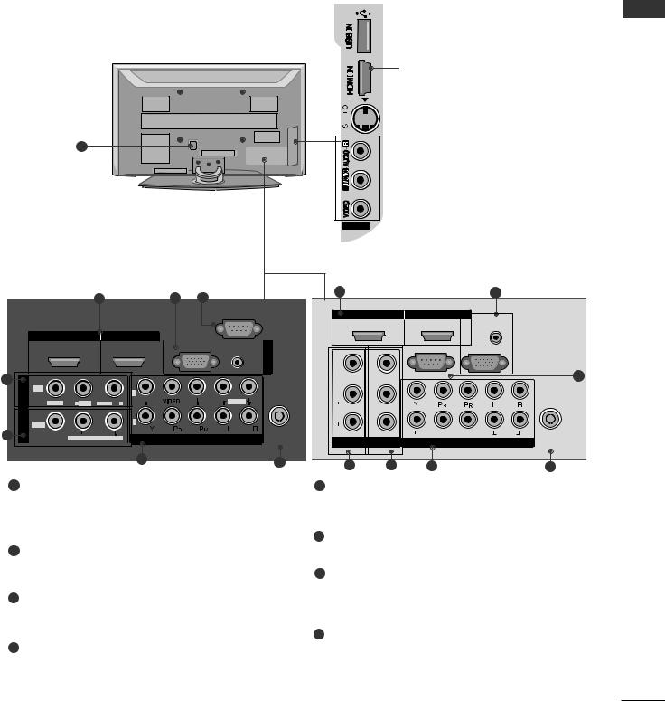
BACK PANEL INFORMATION
■ This is a simplified representation of the back panel. Image shown may differ from your TV.
Plasma TV Models
7
42/50/60PG6*** |
|
|
|
1 |
2 |
8 |
|
|
|
RS-232C IN |
|
|
|
(CONTROL) |
|
HDMI/DVI IN |
HDMI IN |
|
|
1 |
2 |
RGB(PC) AUDIO |
IN |
|
|
(RGB/DVI) |
RGB |
|
|
|
|
3 |
|
|
|
IN 1 |
2 |
|
|
|
|
|
VIDEO |
L/MONO |
AUDIO |
R |
AUDIO |
AV |
|
|
|
|
OUT |
|
|
|
1 |
|
|
|
|
4 |
VARIABLE AUDIO OUT |
COMPONENT IN |
ANTENNA |
IN |
|||
|
|
5 |
6 |
|
|
|
1HDMI Input
Connect a HDMI signal to HDMI IN.
Or DVI(VIDEO)signal to HDMI/DVI port with DVI to HDMI cable.
 USB Input
3 |
HDMI Input |
|
Connect a HDMI signal to
HDMI IN.


 S-Video Input
Connect S-Video out from an S-VIDEO device.
 Audio/Video Input
Connect audio/video output from an external device to these jacks.
AV IN 2
50PG3***, 50/60PG7***
1 |
2 |
HDMI/DVI IN |
HDMI IN |
AUDIO |
|
||
|
1 |
2 |
|
||
|
(RGB/DVI) |
|
|||
VIDEO |
|
RS-232C IN |
RGB IN (PC) |
|
|
VIDEO |
(CONTROL) |
|
8 |
||
AUDIORL/MONO |
AUDIOVARIABLEOUT |
|
|||
|
|
|
|||
|
2 |
|
|
|
|
AV IN 1 |
1 |
VIDEO |
AUDIO |
ANTENNA |
|
AV OUT |
COMPONENT IN |
||||
IN |
|||||
3 |
4 |
5 |
6 |
5Component Input
Connect a component video/audio device to these jacks.
6 Antenna Input
2RGB/Audio Input
Connect the monitor output from a PC to the appropriate input port.
3Audio/Video Input (AV IN 1)
Connect audio/video output from an external device to these jacks.
4AV Output
Connect second TV or monitor to the AV OUT socket on the TV.
Variable Audio Output
Connect an external amplifier or add a subwoofer to your surround sound system.
Connect RF antenna to this jack.
7Power Cord Socket
This TV operates on an AC power. The voltage is indicated on the Specifications page. Never attempt to operate the TV on DC power.
8RS-232C Input (CONTROL) Port
Connect the serial port of the control devices to the RS-232C jack.
(This feature is not available for all models.)
PREPARATION
7

PREPARATION
PREPARATION
32/37LG6*** 42/47LG6***, 42/47/52LG7***
LCD TV Models
 USB Input
7
32/37/42/47LG6***
|
|
1 |
|
|
HDMI/DVI IN |
|
HDMI IN |
||
|
1 |
|
|
2 |
3 |
|
|
|
IN |
IN 1 |
|
|
|
|
|
|
|
COMPONENT |
|
VIDEO |
VARIABLE AUDIO OUT |
|||
L/MONO |
AUDIO |
R |
|
|
AV |
|
|
|
|
OUT |
|
|
|
|
4 |
|
|
|
|
5
|
|
|
|
|
3 |
|
|
|
|
|
|
|
|
|
|
|
HDMI Input |
|
|
|
|
|
|
|
|
|
Connect a HDMI signal |
||
|
|
|
|
|
|
|
to HDMI IN. |
|
|
|
|
|
|
|
|
|
S-Video Input |
|
|
|
|
|
|
|
|
|
Connect S-Video out |
||
|
|
|
|
|
|
|
from an S-VIDEO device. |
||
|
|
|
|
|
|
|
Audio/Video Input |
|
|
|
7 |
|
|
|
|
|
Connect audio/video |
||
|
|
|
|
|
|
output from an external |
|||
|
|
|
|
|
|
|
|||
|
|
|
|
AV IN 2 |
AV IN 2 |
device to these jacks. |
|||
|
|
|
|
|
|
|
|||
|
|
|
42/47/52LG7*** |
|
|
|
|
||
2 |
|
|
|
|
1 |
|
2 |
|
|
|
|
|
|
HDMI/DVI IN |
HDMI IN |
|
|
|
|
RGB (PC) |
AUDIO |
IN |
|
1 |
|
2 |
RGB (PC) |
AUDIO |
IN |
|
(RGB/DVI) |
RGB |
|
|
|
|
|
(RGB/DVI) |
RGB |
|
|
|
|
|
|
|
|
||
|
2 |
3 |
|
IN 1 |
|
|
|
2 |
|
|
ANTENNA |
|
|
|
|
|
|||
|
|
IN |
AV |
VIDEO |
L/MONO AUDIO |
R |
|
|
|
|
|
|
|
|
|
||||
|
|
|
|
|
|
|
1 |
|
|
|
1 |
|
|
OUT |
|
|
|
|
|
|
|
|
|
|
|
|
|
||
VIDEO |
AUDIO |
4 |
|
|
VARIABLE |
|
VIDEO |
AUDIO |
ANTENNA |
|
|
AUDIO OUT |
|
COMPONENT IN |
|
IN |
|||
|
|
6 |
|
|
|
5 |
|
|
6 |
|
|
|
|
|
|
|
|
|
|
32/42LG8***
2
3
4
7
1
HDMI/DVI IN |
HDMI IN |
|
|
1 |
2 |
IN |
AUDIO |
|
RGB |
(RGB/DVI) |
RGB(PC) |
|
||
|
IN1 |
|
AV |
VIDEO |
L(MONO) AUDIO R |
|
|
|
OUT
VARIABLE AUDIO OUT
5 |
|
6 |
COMPONENT |
|
|
|
IN |
|
|
VIDEO |
|
|
AUDIO |
|
1 |
2 |
ANTENNA |
IN |
||
IN |
USB Input |
|
USB |
||
|
||
|
S-Video Input |
|
|
Connect S-Video out |
|
|
from an S-VIDEO device. |
|
|
Audio/Video Input |
|
|
Connect audio/video |
|
AV IN 2 |
output from an external |
|
device to these jacks. |
||
|
8
1HDMI Input
Connect a HDMI signal to HDMI IN.
Or DVI(VIDEO)signal to HDMI/DVI port with DVI to HDMI cable.
(HDMI IN 3 is available for 42/47LG6***, 42/47/52LG7***)
2RGB/Audio Input
Connect the monitor output from a PC to the appropriate input port.
3Audio/Video Input
Connect audio/video output from an external device to these jacks.
4AV Output
Connect second TV or monitor to the AV OUT socket on the TV.
Variable Audio Output
Connect an external amplifier or add a subwoofer to your surround sound system.
5Component Input
Connect a component video/audio device to these jacks.
6Antenna Input
Connect RF antenna to this jack.
7Power Cord Socket
This TV operates on an AC power. The voltage is indicated on the Specifications page. Never attempt to operate the TV on DC power.
PREPARATION
ATTACHING THE TV TO A DESK (Only 32/42LG8***)
The TV must be attached to desk so it cannot be pulled in a forward/backward direction, potentially causing injury or damaging the product. Use only an attached screw.
Stand |
1-Screw
(provided as parts of the product)
Desk
! WARNING
GTo prevent TV from falling over, the TV should be securely attached to the floor/wall per installation instructions. Tipping, shaking, or rocking the machine may cause injury.
9
PREPARATION
PREPARATION
STAND INSTALLATION
■ Image shown may differ from your TV.
When assembling the desk type stand, check whether the bolt is fully tightened.
(If not tightened fully, the product can tilt forward after the product installation.) If you tighten the bolt with excessive force, the bolt can deviate from abrasion of the tightening part of the bolt.
only 42PG6***
1Carefully place the TV screen side down on a cushioned surface to protect the screen from damage.
2Assemble the TV as shown.
Not Using the Desk-type Stand
■ Image shown may differ from your TV.
When installing the wall-mounted unit, use the protection cover for desk-type stand installation. Insert the PROTECTION COVER into the TV until clicking sound.
3Fix the 4 bolts securely using the holes in the back of the TV.
Plasma TV models
10

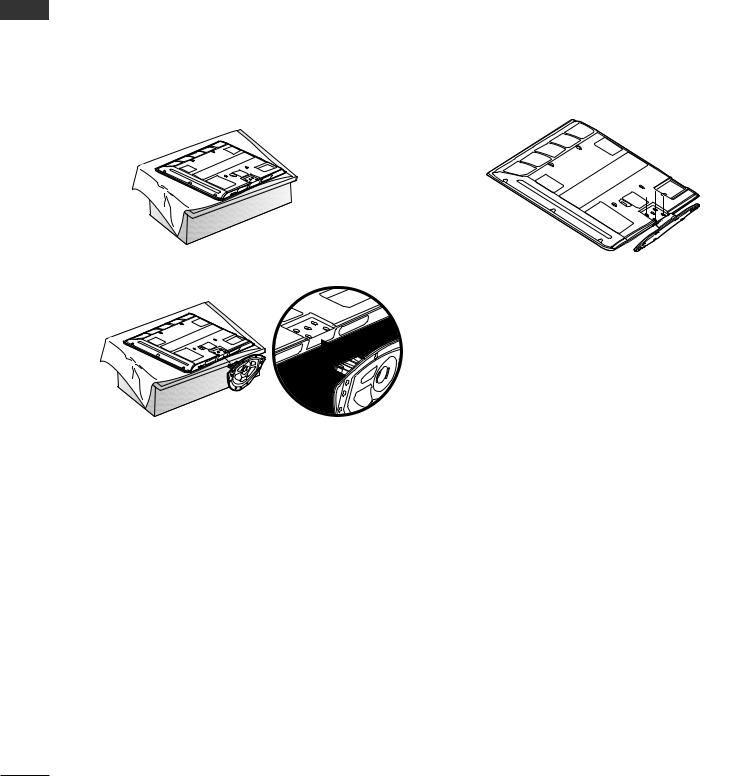
only 32/37/42LG6***
1Carefully place the TV screen side down on a cushioned surface to protect the screen from damage.
2Assemble the parts of the Stand Body with Cover Base of the TV.
32LG6***
 Stand Body
 Cover Base
37LG6***
 Stand Body
 Cover Base
42LG6***
 Stand Body
 Cover Base
3Assemble the TV as shown.
4 |
Fix the 4 bolts |
securely using the holes in the |
back of the TV. |
|
PREPARATION
11
PREPARATION
only 42LG7***, 32/42LG8***
1 Carefully place the TV screen side down on a 3 Assemble the TV as shown. cushioned surface to protect the screen from
damage.
2 Assemble the parts of the Stand Body with |
4 |
Fix the 4 bolts securely using the holes in the |
the Cover Base of the TV. |
|
back of the TV. |
|
|

 Stand Body
 Cover Base
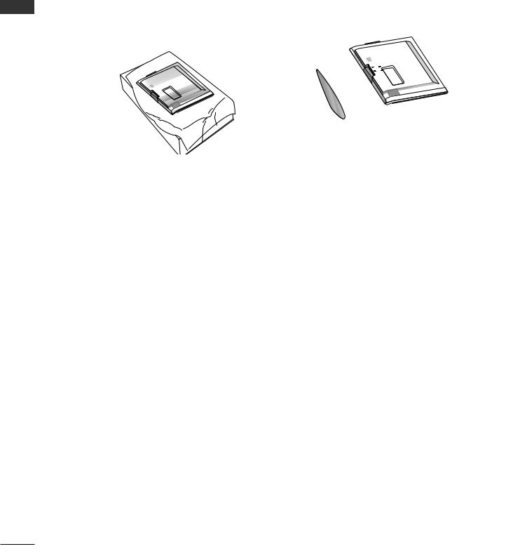
Not Using the Desk-type Stand
When installing the wall-mounted unit, use the protection cover for desk-type stand installation.
■ Image shown may differ from your TV.
32/37/42/47LG6*** |
42/47/52LG7***, 32/42LG8*** |
After removing the protection paper from the protection cover, adhere it to the TV as shown.
Insert the PROTECTION COVER into the TV until clicking sound.
12
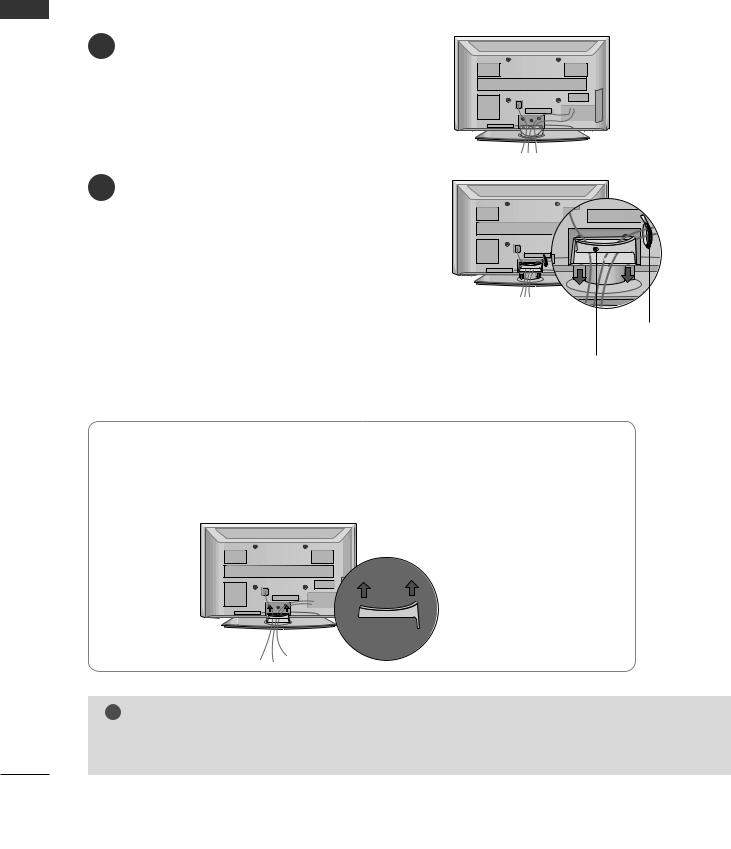
BACK COVER FOR WIRE ARRANGEMENT
■ Image shown may differ from your TV.
42PG6*** |
50/60PG6***, 50/60PG7*** |
||||||||||||||||||||||||||
1 Connect the cables as necessary. |
1 Connect the cables as necessary. |
||||||||||||||||||||||||||
To connect additional equipment, see the |
To connect additional equipment, see the |
||||||||||||||||||||||||||
External Equipment Setup section. |
External Equipment Setup section. |
||||||||||||||||||||||||||
|
|
|
|
|
|
|
|
|
|
|
|
|
|
|
|
|
|
|
|
|
|
|
|
|
|
|
|
|
|
|
|
|
|
|
|
|
|
|
|
|
|
|
|
|
|
|
|
|
|
|
|
|
|
|
|
|
|
|
|
|
|
|
|
|
|
|
|
|
|
|
|
|
|
|
|
|
|
|
|
|
|
|
|
|
|
|
|
|
|
|
|
|
|
|
|
|
|
|
|
|
|
|
|
|
|
|
|
|
|
|
|
|
|
|
|
|
|
|
|
|
|
|
|
|
|
|
|
|
|
|
|
|
|
|
|
|
|
|
|
|
|
|
|
|
|
|
|
|
|
|
|
|
|
|
|
|
|
|
|
|
|
|
|
|
|
|
|
|
|
|
|
|
|
|
|
|
|
|
|
|
|
|
|
|
|
|
|
|
|
|
|
|
|
|
|
|
|
|
|
|
|
|
|
|
|
|
|
|
|
|
|
|
|
|
|
|
|
|
|
|
|
|
|
|
|
|
|
|
|
|
|
|
|
|
|
|
|
|
|
|
|
|
|
|
|
|
|
|
|
|
|
|
|
|
|
|
|
|
|
|
|
|
|
|
|
|
|
|
|
|
|
|
|
|
|
|
|
|
|
|
|
|
|
|
|
|
|
|
|
|
|
|
|
|
|
|
|
|
|
|
|
|
|
|
|
|
|
|
|
|
|
|
|
|
|
|
|
|
|
|
|
|
|
|
|
|
|
|
|
|
|
|
|
|
|
|
|
|
|
|
|
|
|
|
|
|
|
|
|
|
|
|
|
|
|
|
|
|
|
|
|
|
|
|
|
|
|
|
|
|
|
|
|
|
|
|
|
|
|
|
|
|
|
|
|
|
|
|
|
|
|
2 Install the CABLE MANAGEMENT CLIP as shown. 2 Install the CABLE MANAGEMENT CLIP as shown.
|
Fix the Cable Holder |
|
|
CABLE MANAGEMENT CLIP |
as shown and bundle |
|
|
the cables. |
CABLE MANAGEMENT CLIP |
||
|
How to remove the cable management clip
Hold the CABLE MANAGEMENT CLIP with both hands and pull it upward.
42PG6*** |
50/60PG6***, 50/60PG7*** |
Separate CABLE MANAGEMENT from TV by pressing two latches.
PREPARATION
*For the 42PG6*** model, press the center of the CABLE MANAGEMENT CLIP and then lift up it.
!NOTE
G Do not use the CABLE MANAGEMENT CLIP to lift the TV. |
|
- If the TV is dropped, you may be injured or the TV may be damaged. |
13 |
|
PREPARATION
PREPARATION
■ Image shown may differ from your TV.
50PG3***
1Connect the cables as necessary.
To connect additional equipment, see the
EXTERNAL EQUIPMENT SETUP section.
2Install the CABLE MANAGEMENT CLIP as shown.
If your TV has the CABLE HOLDER, install it as shown and bundle the cables.
CABLE HOLDER
CABLE MANAGEMENT CLIP
How to remove the cable management clip
Hold the CABLE MANAGEMENT CLIP with both hands and pull it upward.
! NOTE
G Do not use the CABLE MANAGEMENT CLIP to lift the TV.
- If the TV is dropped, you may be injured or the TV may be damaged.
14
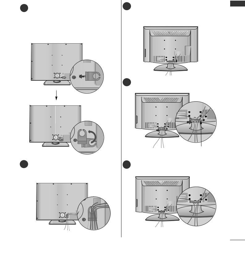
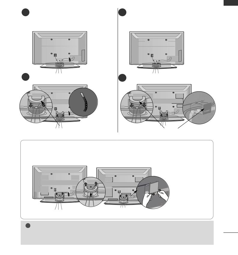
32/37/42/47LG6***
Align the hole with the tab on the CABLE
1MANAGEMENT CLIP.
Turn the CABLE MANAGEMENT CLIP as shown.
Note: This cable management can be broken by excessive pressure.
42/47/52LG7***, 32/42LG8***
1Connect the cables as necessary.
To connect additional equipment, see the
External Equipment Setup section of the manual.
2Open the CABLE MANAGEMENT CLIP as shown and manage the cables.
CABLE MANAGEMENT CLIP
2 |
Connect the cables as necessary. |
Fit the CABLE MANAGEMENT CLIP as |
|
To connect additional equipment, see the External 3 |
|||
shown. |
|||
|
Equipment Setup section. |
|
PREPARATION
15
PREPARATION
PREPARATION
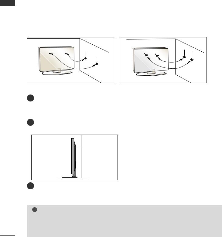
PLEASE SET IT UP CAREFULLY SO THE PRODUCT DOES NOT FALL OVER.
A You should purchase necessary components to fix the TV to the wall on the market.
APosition the TV close to the wall to avoid the possibility of it falling when pushed.
AThe instructions shown below are a safer way to set up the TV, which is to fix it to the wall, avoiding the possibility of it falling forwards if pulled. This will prevent the TV from falling forward and causing injury.
This will also prevent the TV from damage. Ensure that children do not climb or hang from the TV.
1 |
2 |
1 |
2 |
1Use the eye-bolts or TV brackets/bolts to fix the product to the wall as shown in the picture. (If your TV has bolts in the eyebolts, loosen then bolts.)
* Insert the eye-bolts or TV brackets/bolts and tighten them securely in the upper holes.
2Secure the wall brackets with bolts to the wall. Ensure that both brackets are even.
3
3Use a strong cord to secure the TV.
Secure the cord in such a way that it becomes taught when the TV is in position.
!NOTE
GWhen moving the TV undo the cords first.
GUse a platform or cabinet string and large enough to support the size and weight of the TV.
GTo use the TV safely make sure that the height of the bracket on the wall and on the TV is the same.
16
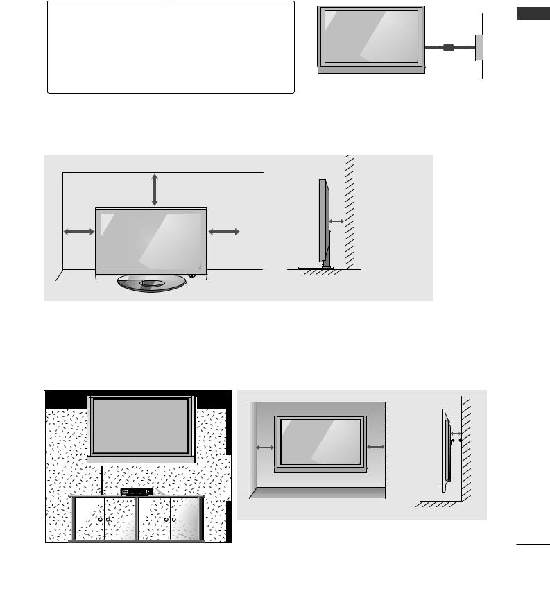
■The TV can be installed in various ways such as on a wall, or on a desktop etc.
■The TV is designed to be mounted horizontally.
EARTHING
Ensure that you connect the earth wire to prevent possible electric shock. If grounding methods are not possible, have a qualified electrician install a separate circuit breaker.
Do not try to earth the TV by connecting it to telephone wires, lightening rods or gas pipes.
DESKTOP PEDESTAL INSTALLATION
For adequate ventilation allow a clearance of 4” (10cm) all around the TV .
4 inches
4 inches
4 inches |
|
|
|
|
|
|
|
4 inches |
|
|
|
|
|
|
|
|
|
||
|
|
|
|
|
|
|
|
|
|
|
|
|
|
|
|
|
|
|
|
|
|
|
|
|
|
|
|
|
|
|
|
|
|
|
|
|
|
|
|
|
|
|
|
|
|
|
|
|
|
|
|
|
|
|
|
|
|
|
|
|
|
|
|
|
|
|
|
|
|
|
|
|
|
|
|
|
|
|
|
Power Supply
Circuit breaker
WALL MOUNT: HORIZONTAL INSTALLATION
For adequate ventilation allow a clearance of 4” (10cm) all around the TV. We recommend that you use a wall mounting bracket of LG brand when mounting the TV to a wall.
 4 inches
4 inches
4 inches |
4 inches |
 4 inches
PREPARATION
17
PREPARATION
■ To prevent damage do not connect to the mains outlet until all connections are made between the devices.
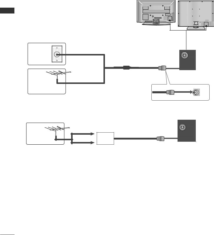
ANTENNA CONNECTION
■ For optimum picture quality, adjust antenna direction.
■ An antenna cable and converter are not supplied.
PREPARATION
Wall |
Multi-family Dwellings/Apartments |
|
(Connect to wall antenna socket) |
||
Antenna |
||
|
||
Socket |
|
RF Coaxial Wire (75 ohm)
Outdoor
Antenna
Single-family Dwellings /Houses
(Connect to wall jack for outdoor antenna)
UHF
Antenna |
Signal |
|
|
|
Amplifier |
|
VHF |
ANTENNA
IN
ANTENNA
IN
■In poor signal areas, to achieve better picture quality it may be necessary to install a signal amplifier to the antenna as shown above.
■If signal needs to be split for two TVs, use an antenna signal splitter for connection.
18
EXTERNAL EQUIPMENT SETUP
■To avoid damaging any equipment, never plug in any power cords until you have finished connecting all equipment.
■This section on EXTERNAL EQUIPMENT SETUP mainly uses diagrams for the 42/50/60PG6*** models.
■Image shown may differ from your TV.
HD RECEIVER SETUP
Connecting with a component cable
1Connect the video outputs (Y, PB, PR) of the digital TV top box to the COMPONENT IN VIDEO jacks on the TV.
2 |
AUDIO |
VIDEO |
|
1 |
|
COMPONENT IN |
|
2Connect the audio output of the digital set-top box to the COMPONENT IN AUDIO jacks on the TV.
3 |
Turn on the digital set-top box. |
1 |
2 |
|
|
||
|
(Refer to the owner’s manual for the digital set-top box.) |
|
|
4 |
Select Component1 input source using the INPUT |
|
|
|
button on the remote control. |
|
|
|
If connected to COMPONENT IN 2, select |
|
|
|
Component2 input source. |
|
|
Signal |
Component |
HDMI1/DVI, HDMI2, HDMI3(except |
||
32/37LG6***, 32/42LG8***) |
||||
|
|
|||
|
|
|
|
|
480i/576i |
Yes |
No |
||
480p/576p |
Yes |
Yes |
||
720p/1080i |
Yes |
Yes |
||
1080p |
Yes |
Yes |
||
(50Hz, 60Hz only) |
(24Hz, 30Hz, 50Hz, 60Hz) |
|||
|
||||
|
|
|
|
|
SETUP EQUIPMENT EXTERNAL
19
EXTERNAL EQUIPMENT SETUP
SETUP EQUIPMENT EXTERNAL
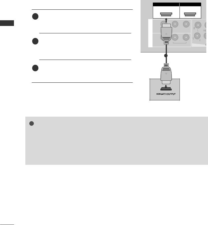
Connecting a set-top box with an HDMI cable
HDMI/DVI IN |
HDMI IN |
1 |
2 |
1 |
Connect the HDMI output of the digital set-top box to |
|
the HDMI/DVI IN 1, HDMI IN 2 or HDMI IN |
|
|
|
|
|
|
3(except 32/37LG6***, 32/42LG8***) jack on the TV. |
IN 1 |
|
|
|
|
|
L/MONO AUDIO R |
|
|
AV |
|
|
OUT |
2 Select HDMI1/DVI, HDMI2 or HDMI3(except |
VARIABLE AUDIO OUT |
|
|
32/37LG6***, 32/42LG8***) input source using the |
|
|
|
|
|
INPUT button on the remote control. |
|
|
|
1 |
3 Turn on the digital set-top box.
(Refer to the owner’s manual for the digital set-top box.)
! NOTE
G TV can receive the video and audio signal simultaneously with using a HDMI cable.
G If the digital set-top box supports Auto HDMI function, the output resolution of the source device will be automatically TV to 1280x720p.
G If the digital set-top box player does not support Auto HDMI, you need to TV the output resolution appropriately.
To get the best picture quality, adjust the output resolution of the source device to 1280x720p. (42/47LG6***, 42/47/52LG7***, 50PG3***, 50/60PG7***, 32/42LG80F* : 1920x1080i/1080p)
20
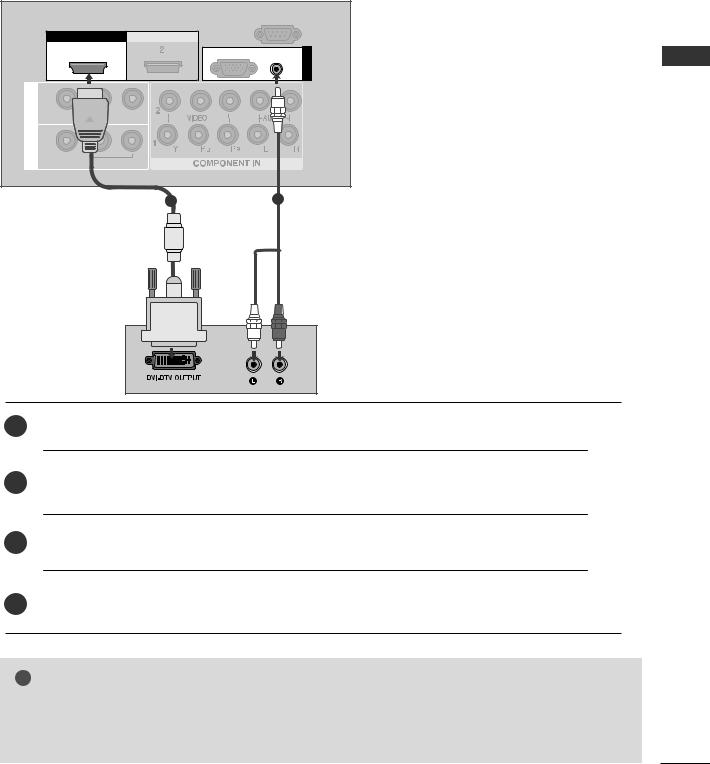
Connecting with a HDMI to DVI cable |
|||||
|
|
|
|
RS-232C IN |
|
|
|
|
|
(CONTROL) |
|
HDMI/DVI IN |
HDMI IN |
|
|
|
|
|
1 |
|
RGB(PC) |
AUDIO |
IN |
|
|
|
|
(RGB/DVI) |
RGB |
|
|
|
|
|
|
OUT |
|
|
|
|
EXTERNAL |
IN 1 |
|
|
|
|
|
VIDEO |
AUDIO R |
|
|
|
|
AV |
|
|
|
|
SETUPEQUIPMENT |
VARIABLE AUDIO OUT |
|
|
|
||
|
|
|
|
||
|
|
1 |
|
2 |
|
1Connect the DVI output of the digital set-top box to the HDMI/DVI IN 1 jack on the TV.
2Connect the audio output of the digital set-top box to the AUDIO(RGB/DVI) jack on the TV.
3Turn on the digital set-top box. (Refer to the owner’s manual for the digital set-top box.)
4Select HDMI1/DVI input source using the INPUT button on the remote control.
!NOTE
GHDMI2, HDMI3(except 32/37LG6***, 32/42LG8***) source does not support DVI source.
GIf the set-top box has a DVI output and no HDMI output, a separated audio connection is necessary.
GIf the set-top box does not support Auto DVI, you need to set the output resolution appropriately.
21
EXTERNAL EQUIPMENT SETUP
SETUP EQUIPMENT EXTERNAL
DVD SETUP
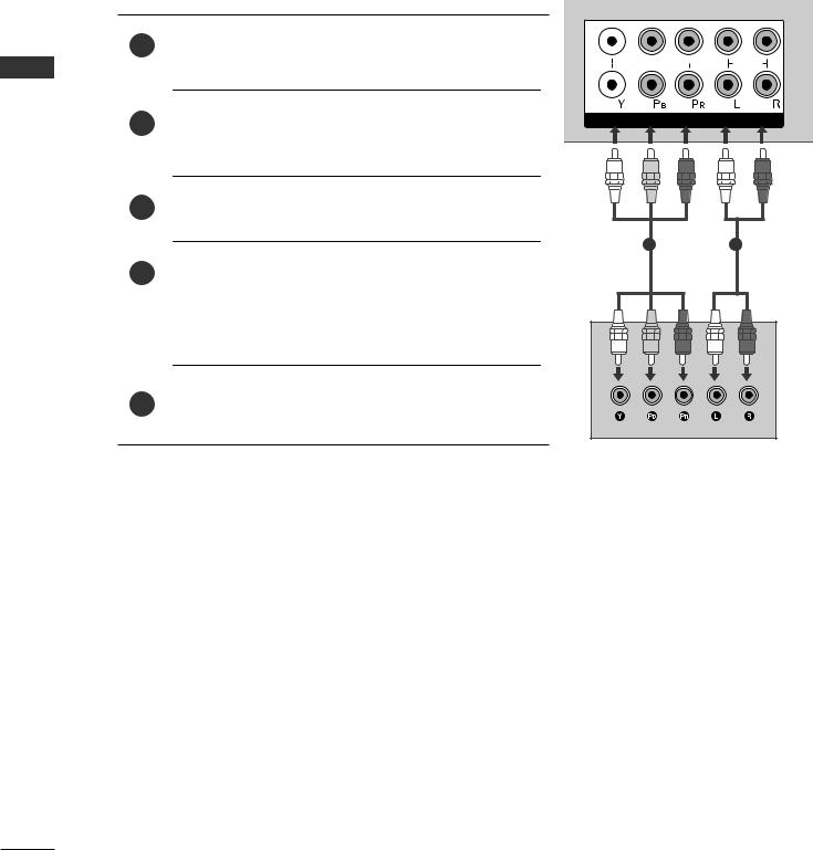
Connecting with a component cable
1 |
Connect the video outputs (Y, PB, PR) of the DVD to the |
COMPONENT IN VIDEO jacks on the TV. |
2Connect the audio outputs of the DVD to the COMPONENT IN AUDIO jacks on the TV.
2 
VIDEO |
AUDIO |
1
COMPONENT IN
3 |
Turn on the DVD player, insert a DVD. |
|
|
1 |
2 |
4 |
Select Component1 input source using the INPUT button on |
|
|
the remote control. |
|
|
If connected to COMPONENT IN 2, select Component 2 |
|
|
input source. |
|
5 |
Refer to the DVD player's manual for operating instructions. |
|
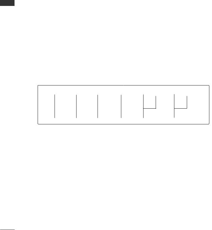
Component Input ports
To achieve better picture quality, connect a DVD player to the component input ports as shown below.
Component ports on the TV |
Y |
PB |
PR |
|
|
|
|
|
|
|
|
|
Y |
PB |
PR |
Video output ports |
Y |
B-Y |
R-Y |
on DVD player |
Y |
Cb |
Cr |
|
Y |
Pb |
Pr |
|
|
|
|
22
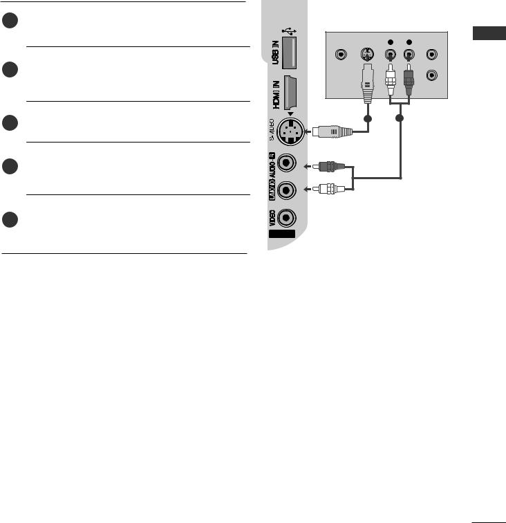
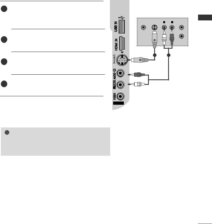
Connecting with a S-Video cable
Connect the S-VIDEO output of the DVD to the
1S-VIDEO input on the TV.
2Connect the audio outputs of the DVD to the AUDIO input jacks on the TV.
3Turn on the DVD player, insert a DVD.
4Select AV2 input source using the INPUT button on the remote control.
5Refer to the DVD player's manual for operating instructions.
VIDEO |
S-VIDEO |
L |
R |
ANT IN |
|||||
|
|
|
|
|
|
|
|
|
|
|
|
|
|
|
|
|
|
|
|
3
ANT OUT
1 2
AV IN 2
SETUP EQUIPMENT EXTERNAL
23
EXTERNAL EQUIPMENT SETUP
SETUP EQUIPMENT EXTERNAL
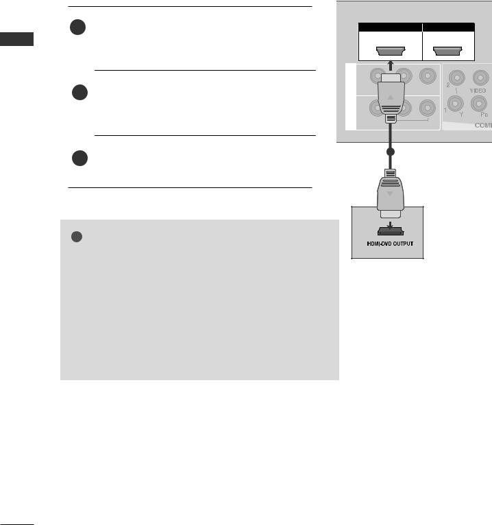
Connecting with a HDMI cable
1 Connect the HDMI output of the DVD to the |
HDMI/DVI IN |
HDMI IN |
HDMI/DVI IN 1, HDMI IN 2 or HDMI IN |
1 |
2 |
3(except 32/37LG6***, 32/42LG8***) jack on the TV. |
|
|
2 |
|
IN 1 |
|
|
Select HDMI1/DVI, HDMI2 or HDMI3(except |
AV |
AUDIO |
R |
|
|
|
VIDEO |
||
|
32/37LG6***, 32/42LG8***) input source using the |
OUT |
|
|
|
INPUT button on the remote control. |
|
|
|
|
|
|
|
|
|
|
VARIABLE AUDIO OUT |
||
3 |
Refer to the DVD player's manual for operating |
|
1 |
|
|
|
|
||
|
instructions. |
|
|
|
! NOTE
G The TV can receive video and audio signals simultaneously when using a HDMI cable.
G If the DVD player supports Auto HDMI function, the output resolution of the source device will be automatically TV to 1280x720p.
G If the DVD player does not support Auto HDMI, you must TV the output resolution appropriately.
To get the best picture quality, adjust the output resolution of the source device to 1280x720p.
(42/47LG6***, 42/47/52LG7***, 50PG3***, 50/60PG7***, 32/42LG80F* : 1920x1080i/1080p)
24
VCR SETUP
■To avoid picture noise (interference), allow adequate distance between the VCR and TV.
■Typically a frozen still picture from a VCR. If 4:3 picture format is used for an extended period the fixed images on the sides of the screen may remain visible.
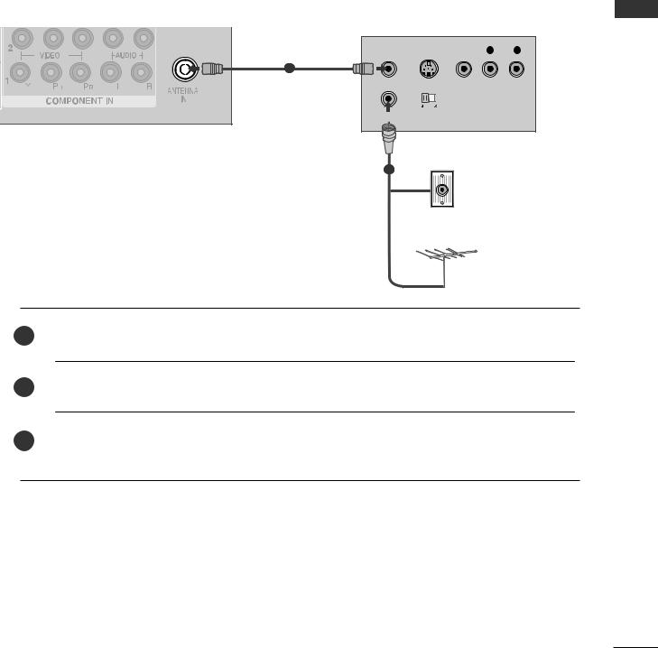
Connecting with a RF cable
ANT OUT S-VIDEO VIDEO |
L |
R |
|
|
|
|
|
|
|
|
|
1
ANTENNA
IN
OUTPUT
SWITCH
Wall Jack
2
Antenna
1Connect the ANT OUT socket of the VCR to the ANTENNA IN socket on the TV.
2 Connect the antenna cable to the ANT IN socket of the VCR.
3Press the PLAY button on the VCR and match the appropriate programme between the TV and VCR for viewing.
SETUP EQUIPMENT EXTERNAL
25
EXTERNAL EQUIPMENT SETUP
|
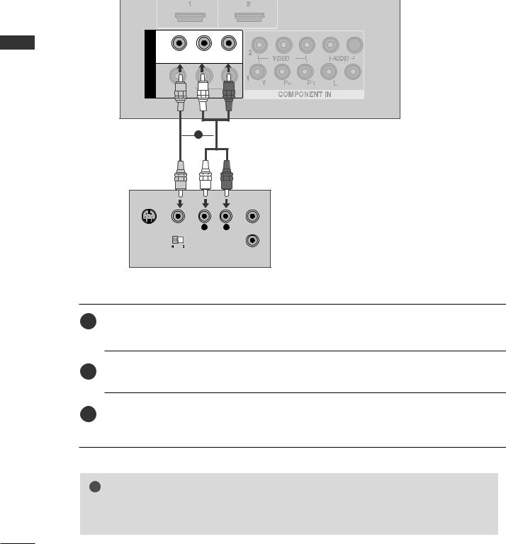
Connecting with a RCA cable |
||
|
IN 1 |
|
|
EXTERNAL |
VIDEO L/MONO |
AUDIO |
R |
AV |
|
|
|
|
|
|
|
|
OUT |
|
|
SETUPEQUIPMENT |
VARIABLE AUDIO |
|
|
1 |
|
|
|
|
|
|
|
S-VIDEO VIDEO |
L |
R |
ANT IN |
OUTPUT |
|
|
ANT OUT |
SWITCH |
|
|
|
1Connect the AUDIO/VIDEO jacks between TV and VCR. Match the jack colours (Video = yellow, Audio Left = white, and Audio Right = red)
2Insert a video tape into the VCR and press PLAY on the VCR. (Refer to the VCR owner’s manual.)
3Select AV1 input source using the INPUT button on the remote control. If connected to AV IN 2, select AV2 input source.
! NOTE
G If you have a mono VCR, connect the audio cable from the VCR to the AUDIO L/MONO jack of the TV.
26
Connecting with a S-Video cable
Connect the S-VIDEO output of the VCR to the
1S-VIDEO input on the TV. The picture quality is
improved; compared to normal composite (RCA cable)
|
input. |
VIDEO S-VIDEO |
L |
R ANT IN |
2 |
Connect the audio outputs of the VCR to the AUDIO |
3 |
|
|
input jacks on the TV. |
|
|
ANT OUT |
|
|
|
|
|
|
|
|
1 |
|
2 |
3Insert a video tape into the VCR and press PLAY on the VCR. (Refer to the VCR owner’s manual.)
4Select AV2 input source using the INPUT button on the remote control.
AV IN 2
! NOTE
GIf both S-VIDEO and VIDEO sockets have been connected to the S-VHS VCR simultaneously, only the S-VIDEO can be received.
SETUP EQUIPMENT EXTERNAL
27

EXTERNAL EQUIPMENT SETUP
OTHER A/V SOURCE SETUP
EXTERNAL |
3 |
EQUIPMENT |
|
SETUP |
1 |
|
|
|
AV IN 2 |
Camcorder
Video Game Set
VIDEO L R
1Connect the AUDIO/VIDEO jacks between TV and external equipment. Match the jack colours. (Video = yellow, Audio Left = white, and Audio Right = red)
2Select AV2 input source using the INPUT button on the remote control. If connected to AV IN 1, select AV1 input source.
3Operate the corresponding external equipment. Refer to external equipment operating guide.
28
 Loading...