


PLASMA TV
OWNER’S MANUAL
Please read this manual carefully before operating your set. Retain it for future reference.
Record model number and serial number of the set.
See the label attached on the back cover and quote this information to your dealer when you require service.
Model number |
: |
Serial number |
: |
P/NO : 3828VA0565M (MF056B, 141K TX)
Safety Warnings
Safety Instructions
 WARNING
Do not place the set in direct sunlight or near heat sources such as heat registers, stove and so on.
- This may cause a fire.
Do not use the set in damp place such as a bathroom or any place where it is likely to get wet.
- This may cause a fire or could give an electric shock.
Bend antenna cable between inside and outside building to prevent rain from flowing in.
-This may cause water damaged inside the set and could give an electric shock.
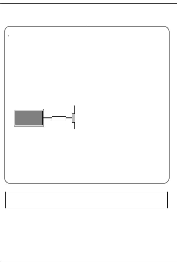
Earth wire should be connected.
-If the earth wire is not connected, there is possible a danger of electric shock caused by the current leakage.
-If grounding methods are not possible, a separate circuit breaker should be employed and installed by a qualified electrician.
Power supplier
Short-circuit
breaker
-Do not connect ground to telephone wires, lightning rods or gas pipe.
Apparatus shall not be exposed to dripping or splashing and no objects filled with liquids, such as vases, shall be placed on the apparatus.
-This may cause a fire or could give an electric shock.
Do not insert any object into the exhaust vent.
-This may cause a fire or could give an electric shock.
Do not place heavy objects on the set.
- This may cause serious injury to a child or adult.
Do not use water while cleaning the set.
-This may cause damaged the set or could give an electric shock.
In case of smoke or strange smell from the set, switch it off ,unplug it from the wall outlet and contact your dealer or service centre.
- This may cause a fire or could give an electric shock.
Do not attempt to service the set yourself. Contact your dealer or service centre.
-This may cause damaged the set or could give an electric shock.
During storm activity, unplug the set from the wall outlet and don’t touch the antenna cable.
-This may cause damaged the set or could give an electric shock.
DISCONNECTING DEVICE FROM MAINS
-Mains plug is the disconnecting device. The plug must remain readily operable.
WARNING
TO REDUCE THE RISK OF FIRE AND ELECTRIC SHOCK, DO NOT EXPOSE THIS PRODUCT TO RAIN OR MOISTURE.
2 PLASMA TV
Safety Warnings
ENGLISH
* Safety instructions have two kinds of information, and each meaning of it is as below.
WARNING The violation of this instruction may cause serious injuries and even death.
The violation of this instruction may cause light injuries or damage of the NOTES product.
 Take care of danger that may happen under specific condition.
 NOTES
NOTES
Never touch the power plug with a wet hand.
- This may cause an electric shock.
Disconnect from the mains and remove all connections before moving.
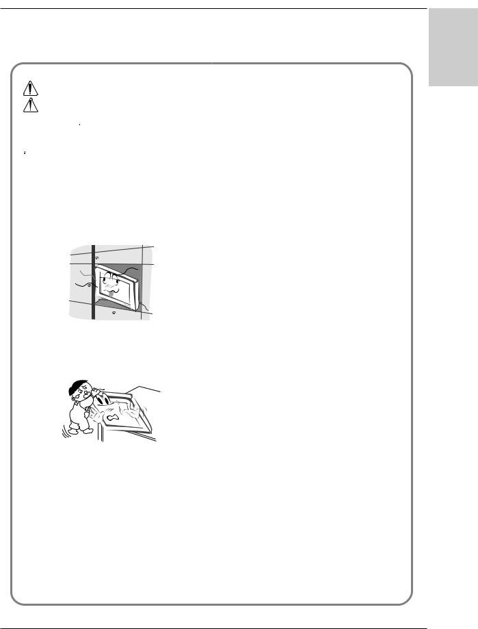
Do not place the set in a built-in installation such as a bookcase or rack.
- Ventilation required.
When installing the set on a table, be careful not to place the edge of its stand on the end of the table.
-This may cause the set to fall, causing serious injury to a child or adult, and serious damage to the set.
Do not place an outside antenna in the vicinity of overhead power lines or other electric light or power circuits.
- This may cause an electric shock.
There should be enough distance between an outside antenna and power lines to keep the former from touching the latter even when the antenna falls.
- This may cause an electric shock.
Do not pull the plug not the cord when disconnecting.
- This may cause a fire.
Ensure the power cord doesn’t trail across any hot objects like a heater.
- This may cause a fire or an electric shock.
Do not plug in unit if power cord or plug is damaged or the connecting part of the power outlet is loose.
- This may cause a fire or an electric shock.
Dispose of used batteries carefully to prevent a child from eating them.
- In case of a child eating them, contact doctor immediately.
When moving the set assembled with speakers do not carry holding the speakers.
-This may cause the set to fall, causing serious injury to a child or adult, and serious damage to the Monitor.
Unplug this product from the wall outlet before cleaning. Do not use liquid cleaners or aerosol cleaners.
- This may cause damage the set or could give an electric shock.
Contact the service centre once a year to clean the internal part of the set.
- Accumulated dust can cause mechanical failure.
The distance between eyes and the screen should be approx. 5 ~ 7 times the diagonal length of the screen away.
- If not, eyes will strain.
Unplug the set from the wall outlet when it is left unattended and unused for long periods of time or in the occurrance of a state of emergency.
-Accumulated dust may cause a fire or an electric shock from deterioration through electric leakage.
Owner’s Manual 3

Contents
Contents
Safety Warnings
Safety Instructions . . . . . . . . . . . . . . . . . . . . . . .2~3
Introduction
Remote Control Key Functions . . . . . . . . . . . . . . . .5
Location and Function of Controls . . . . . . . . . . .6~7
Installation
External Equipment Viewing Setups . . . . . . . . . . . .8
Displayable Monitor Specification . . . . . . . . . . . . . .9
HDMI . . . . . . . . . . . . . . . . . . . . . . . . . . . . . . . . . .10
Accessories . . . . . . . . . . . . . . . . . . . . . . . . . . . . .11
Installation Options . . . . . . . . . . . . . . . . . . . . . . .12
Operation
Turning on the Set . . . . . . . . . . . . . . . . . . . . . . . .13 On-Screen Menu Language Selection (option) . . .13 On screen menus . . . . . . . . . . . . . . . . . . . . . . . .14
Channel Menu Options |
|
Auto Programme Tuning . . . . . . . . . . . . . . . . . . . |
15 |
Manual Programme Tuning . . . . . . . . . . . . . . . . . |
15 |
Fine Tuning . . . . . . . . . . . . . . . . . . . . . . . . . . . . . |
15 |
Assigning a Station Name . . . . . . . . . . . . . . . . . . |
16 |
Booster (option) . . . . . . . . . . . . . . . . . . . . . . . . . . |
16 |
Programme Edit . . . . . . . . . . . . . . . . . . . . . . . . . . |
16 |
Favourite Programme . . . . . . . . . . . . . . . . . . . . . |
16 |
Calling up the Programme Table . . . . . . . . . . . . . |
16 |
Picture Menu Options |
|
PSM (Picture Status Memory) . . . . . . . . . . . . . . .17 CSM (Colour Status Memory) . . . . . . . . . . . . . . .17 Manual Colour Temperature Control . . . . . . . . . .17  . . . . . . . . . . . . . . . . . . . . . . . . . . . . . . . . . .17 sRGB . . . . . . . . . . . . . . . . . . . . . . . . . . . . . . . . .17 ACM (Active Colour Management) . . . . . . . . . . . .17 Manual Picture Control . . . . . . . . . . . . . . . . . . . .17
Sound Menu Options
SSM (Sound Status Memory) . . . . . . . . . . . . . . . .17 BBE . . . . . . . . . . . . . . . . . . . . . . . . . . . . . . . . . . .17 AVL (Auto Volume Leveler) . . . . . . . . . . . . . . . . .17 Adjusting Sound Control . . . . . . . . . . . . . . . . . . .17 TV speaker . . . . . . . . . . . . . . . . . . . . . . . . . . . . .18 Stereo/Dual Reception . . . . . . . . . . . . . . . . . . . . .18 NICAM Reception (option) . . . . . . . . . . . . . . . . . .18
Time Menu Options
Setting the Clock . . . . . . . . . . . . . . . . . . . . . . . . .18
Setting the On/Off Timer . . . . . . . . . . . . . . . . . . . |
18 |
Auto Sleep . . . . . . . . . . . . . . . . . . . . . . . . . . . . . . |
18 |
Sleep Timer . . . . . . . . . . . . . . . . . . . . . . . . . . . . . |
18 |
Special Menu Options
Child Lock . . . . . . . . . . . . . . . . . . . . . . . . . . . . . .19 ISM (Image Sticking Minimization) Method . . . . . .19 Low Power . . . . . . . . . . . . . . . . . . . . . . . . . . . . . .19  Demo . . . . . . . . . . . . . . . . . . . . . . . . . . . . .19 Index . . . . . . . . . . . . . . . . . . . . . . . . . . . . . . . . . .19
Screen Menu Options
Auto Configure . . . . . . . . . . . . . . . . . . . . . . . . . .19 Manual Configure . . . . . . . . . . . . . . . . . . . . . . . .19 Selecting Wide VGA/XGA mode . . . . . . . . . . . . .19 Setting Picture Format . . . . . . . . . . . . . . . . . . . . .20 Picture Size Zoom . . . . . . . . . . . . . . . . . . . . . . . .20 Screen Position . . . . . . . . . . . . . . . . . . . . . . . . . .20 Cinema . . . . . . . . . . . . . . . . . . . . . . . . . . . . . . . .20 NR (Noise Reduction) . . . . . . . . . . . . . . . . . . . . .20 Initializing (Reset to original factory value) . . . . . .20
Teletext (option)
Teletext Language Selection . . . . . . . . . . . . . . . .20 Switch on/off . . . . . . . . . . . . . . . . . . . . . . . . . . . .20 SIMPLE Text (option) . . . . . . . . . . . . . . . . . . . . . .21 TOP Text (option) . . . . . . . . . . . . . . . . . . . . . . . . .21 FASTEXT . . . . . . . . . . . . . . . . . . . . . . . . . . . . . .21 Special Teletext Functions . . . . . . . . . . . . . . . . . .21
PIP (Picture-in-Picture) Feature
Watching PIP . . . . . . . . . . . . . . . . . . . . . . . . . . . .22 Programme Selection for Sub Picture . . . . . . . . . .22 Selecting an Input Signal Source for the PIP . . . .22 Moving the PIP (PIP mode only) . . . . . . . . . . . . .22 POP (Picture-out-of-Picture: Channel Scan) . . . . .22 Picture Size . . . . . . . . . . . . . . . . . . . . . . . . . . . . .22 Adjusting the screen for the PIP . . . . . . . . . . . . . .22 Adjusting PIP Transparency (PIP mode only) . . . .22
Notes on Memory Card . . . . . . . . . . . . . . . . .23~25 JPEG File Viewing Options . . . . . . . . . . . . . .26~30 MP3 File Playing Operation . . . . . . . . . . . . . .31~34
Miscellaneous
Programming the Remote (option) . . . . . . . . . . . .35
Programming Codes (option) . . . . . . . . . . . . .36~37
Troubleshooting Checklist . . . . . . . . . . . . . . . . . .38
Product Specifications . . . . . . . . . . . . . . . . . . . . .39
After reading this manual, keep it in a place where the user can refer to easily.
Disposal of your old appliance
1.When this crossed-out wheeled bin symbol is attached to a product it means the product is covered by the European Directive 2002/96/EC.
2.All electrical and electronic products should be disposed of separately from the municipal waste stream via designated collection facilities appointed by the government or the local authorities.
3.The correct disposal of your old appliance will help prevent potential negative consequences for the environment and human health.
4.For more detailed information about disposal of your old appliance, please contact your city office, waste disposal service or the shop where you purchased the product.
4 PLASMA TV
Introduction
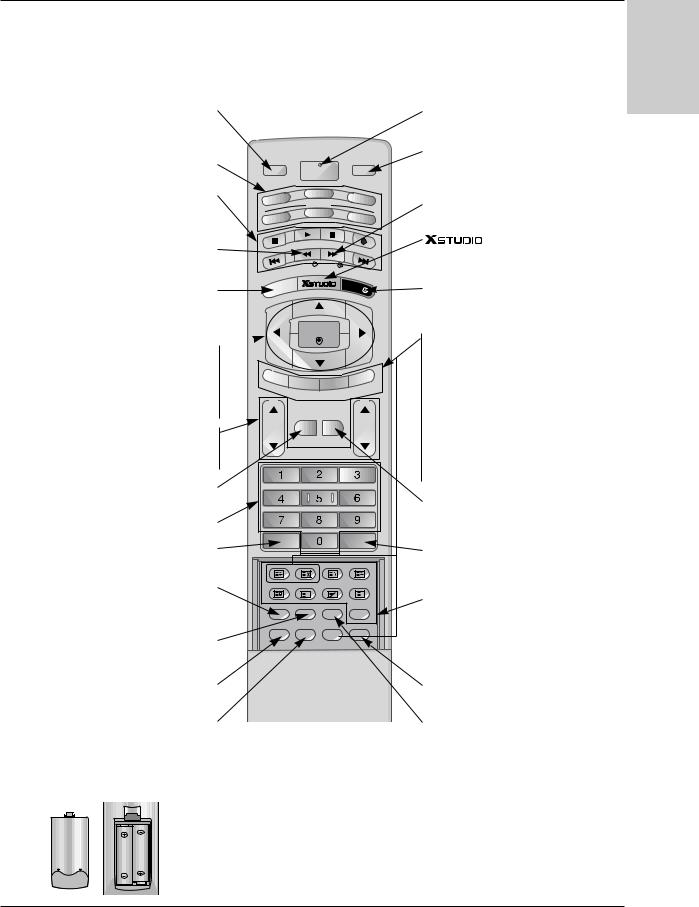
Remote Control Key Functions
-When using the remote control aim it at the remote control sensor of the set.
-There maybe a defect in consecutive operation of remote control in a specified brightness according to this set.
INPUT
Selects the TV, AV1, AV2, S-Video, AV3, AV4, AV5, Component, RGB or HDMI modes. switches the set on from standby.
MODE
Selects another device.
VCR BUTTONS
Controls a video cassette recorder. These buttons are used for X-Studio.
For further details, see the ‘X-Studio’ section.
INFO
Displays information on top of the screen whilst watching the TV.
MENU
Displays on screen menus one by one. Exits the current menu.
Memorizes menu changes.
OK  accepts your selection or displays the
current mode.
D / E or F / G
Adjusts menu settings.
Selects menu item.
VOL D / E (Volume Up/Down)
Increases/decreases sound level.
PR D / E (Programme Up/Down)
Selects a programme.
MUTE
Switches the sound on or off.
NUMBER buttons
LIST
Displays the programme table.
PSM
Adjusts the factory preset picture according to the room.
SSM
To select the sound appropriate to your viewing programme.
|
|
|
|
|
|
|
|
|
POWER |
|
|
|
|
|
|
|
|
|
|
switches the set on from standby or off to |
|
|
|
|
|
|
|
|
|
|
standby. |
|
|
|
|
|
|
|
|
|
|
MULTIMEDIA |
|
INPUT |
|
|
MULTIMEDIA |
Selects the Component, RGB or HDMI |
||||||
|
|
|
|
POWER |
|
|
|
modes. |
||
|
|
|
|
|
|
|
|
|
switches the set on from standby. |
|
|
|
|
|
DVD |
VCR |
|
||||
TV |
|
|
MODE |
MARK |
||||||
|
|
|
|
|
|
|
||||
AUDIO |
CABLE |
STB |
Selects the wanted functions. |
|||||||
|
|
|||||||||
|
|
|
|
|
|
|
|
|
Brings up the menu to select the Photo or |
|
|
|
|
|
INFO i |
MARK |
|
|
|
Music mode of Xstudio for memory cards. |
|
|
E |
|
|
|
EXIT |
|
EXIT |
|||
M |
NU |
|
|
|
|
|
||||
|
|
|
|
|
|
|
||||
|
|
|
|
|
|
|
|
|
Clears all on-screen displays and returns |
|
|
|
|
|
|
|
|
|
|
to TV viewing from any menu. |
|
|
|
|
|
OK |
|
|
|
PIP |
||
|
|
|
|
|
|
|
|
|
||
|
|
|
|
|
|
|
|
|
Switches the sub picture on or off. |
|
|
|
|
|
|
|
|
|
|
Selects PIP, POP or DW modes. |
|
|
|
|
|
|
|
|
|
|
PIP PR + /- |
|
P |
|
|
|
|
|
|
|
PUT |
Selects a programme for the sub picture. |
|
|
|
|
|
|
|
|
|
|||
IP |
PR |
|
|
|
|
|
SWAP |
|||
|
- |
PIP PR + |
SWAP |
PIP |
IN |
|||||
|
|
|
|
|
|
|
|
|
Alternates between main and sub picture. |
|
|
|
|
|
|
|
|
|
|
PIP INPUT |
|
VOL |
|
MUTE |
FAV |
PR |
Selects the input mode for the sub picture. |
|||||
|
SIZE |
|||||||||
|
|
|
|
|
|
|
|
|
||
|
|
|
|
|
|
|
|
|
Adjusts the sub picture size. |
|
|
|
|
|
|
|
|
|
|
POSITION |
|
|
|
|
|
|
|
|
|
|
Moves the sub picture to D / E or F / G |
|
|
|
|
|
|
|
|
|
|
direction. |
|
|
|
|
|
|
|
|
|
|
FAV |
|
|
|
|
|
|
|
|
|
|
selects a favourite programme. |
|
|
LIST |
|
|
Q.VIEW |
|
|||||
|
|
|
|
|
|
|
|
|
Q.VIEW |
|
|
SIZE |
POSITION |
INDEX |
HOLD |
|
Returns to the previously viewed |
||||
|
|
|
|
|
|
|
|
|
programme. |
|
|
TIME |
REVEAL |
MIX |
MODE |
|
|
||||
|
|
|
|
? |
|
M |
|
TEXT |
||
|
PSM |
SSM |
ARC |
TEXT |
|
|||||
|
|
These buttons are used for teletext. |
||||||||
|
|
|
|
|
|
|
|
|
||
SLEEP |
I/II |
PIP |
M/C EJECT |
For further details, see the ‘Teletext’ section. |
||||||
Note : In teletext mode, the PIP PR +/-, |
||||||||||
|
|
|
|
|
|
|
|
|
||
|
|
|
|
|
|
|
|
|
SWAP and PIP INPUT buttons are used |
|
|
|
|
|
|
|
|
|
|
for teletext function. |
|
SLEEP |
M/C EJECT |
Sets the sleep timer. |
Remove the Memory Card. |
I/II |
ARC |
Selects the language during dual language |
Changes the picture format. |
broadcast. |
|
Selects the sound output. |
|
Installing Batteries
• Open the battery compartment cover on the back side and insert the batteries with correct polarity.
•Install two 1.5V alkaline batteries of AA type. Don’t mix used batteries with new batteries.
ENGLISH
Owner’s Manual 5
Introduction
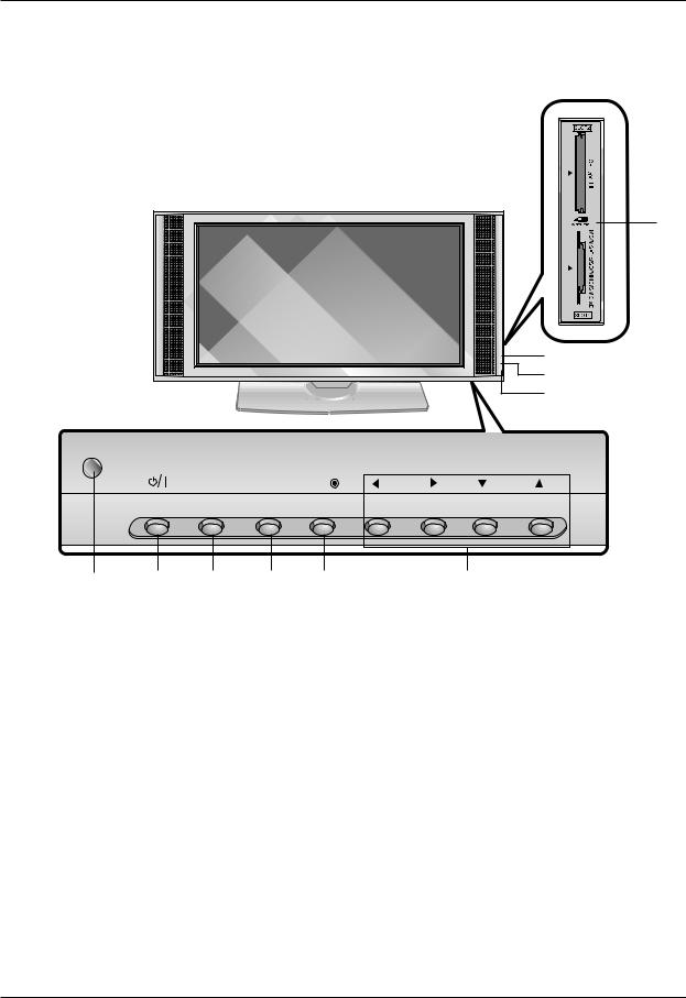
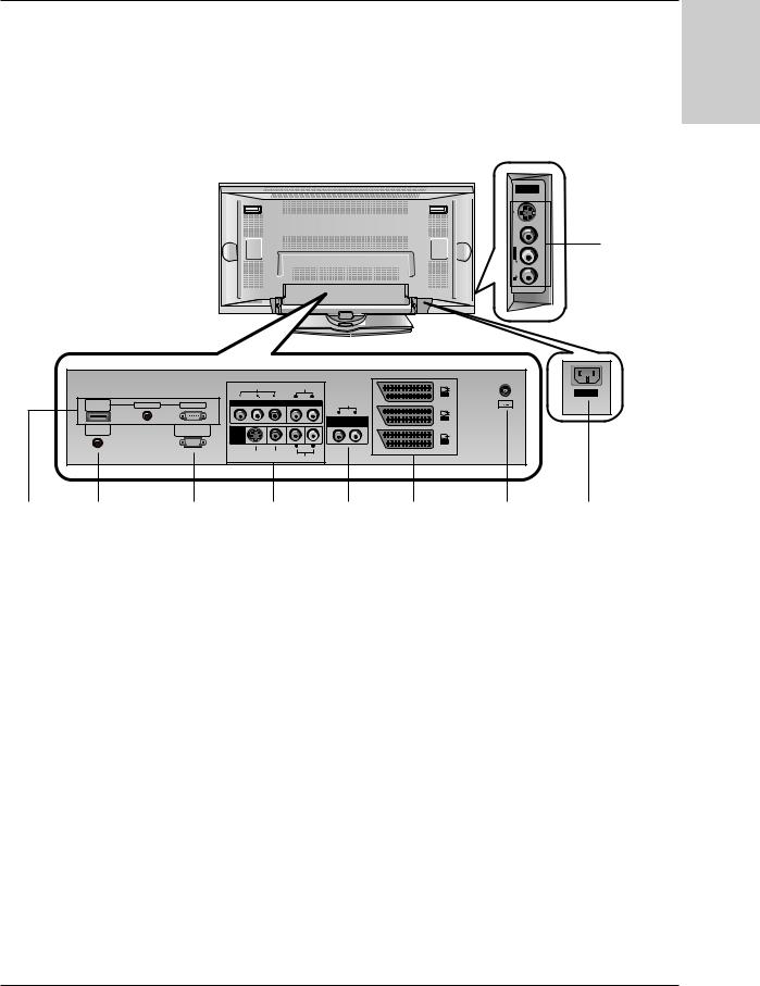
Location and Function of Controls
-Shown is a simplified representation of the set.
-Here shown may be somewhat different from your set.
|
|
|
<Front Panel Controls> |
|
||
|
|
|
|
|
|
10 |
|
|
|
|
|
|
7 |
|
|
|
|
|
|
8 |
|
|
|
|
|
|
9 |
|
|
INPUT |
MENU |
OK |
VOL |
PR |
1 |
2 |
3 |
4 |
5 |
|
6 |
1.Remote Control Sensor
2.Power Button
Switches the set on from standby or off to standby.
3.INPUT Button
Selects the TV, AV1, AV2, S-Video, AV3, AV4, AV5, Component, RGB or HDMI modes.switches the set on from standby.
4.MENU
Displays on screen menus one by one. Exits the current menu.
Memorizes menu changes.
5.OK
Accepts your selection or displays the current mode.
6.D / E (Programme Up/Down)
Selects a programme or a menu item.
Switches the set on from standby.
F / G (Volume Up/Down)
Adjusts the volume. Adjusts menu settings.
7.INDEX
Switches FRONT Display on or off.
8.Power Indicator
Illuminates red in standby mode, illuminates green when the set is turned on.
9.Intelligent Eye
Adjusts picture according to the surrounding conditions.
10.Memory Card Slots 1, 2
6 PLASMA TV
Location and Function of Controls
<Back Panel>
Introduction
ENGLISH
|
AV5 |
|
|
S-VIDEO |
|
VIDEO |
9 |
|
L/MONO |
||
|
||
AUDIO |
|
|
R |
|
|
|
|
VIDEO |
AUDIO |
|
|
|
|
|
L |
R |
|
AV1 |
|
|
|
|
|
||
HDMI/ |
AUDIO INPUT |
RGB INPUT |
COMPONENT |
AUDIO |
|
Antenna |
DVI(VIDEO) |
|
|
|
|
||
|
|
|
|
L |
R |
|
|
|
|
|
VARIABLE |
AV2 |
|
REMOTE |
|
RS-232C INPUT |
|
AUDIO OUT |
|
|
|
|
|
|
|
||
CONTROL |
|
(CONTROL/SERVICE) |
AV4 |
|
|
|
|
AV3 |
L |
R |
(MONO)
S-VIDEO VIDEO
AUDIO
AC INPUT |
1 |
2 |
3 |
4 |
1.HDMI(DVI VIDEO) / AUDIO INPUT / RGB INPUT
Connect the monitor output socket of the PERSONAL COMPUTER, DVD or STB to this socket.
Note:
If you want to use RGB/DVI audio, we strongly recommend that you use the cable that has a core, or the EMI Filter core along with separate cable.
2.REMOTE CONTROL
3.RS-232C INPUT(CONTROL/SERVICE) PORT
Connect to the RS-232C port on a PC.
4.COMPONENT INPUT
Connect DVD video outputs to Y, PB, PR of COMPONENT INPUT and audio outputs to Audio sockets of AUDIO INPUT.
AUDIO/VIDEO IN SOCKETS (AV4)
Connect the audio/video out sockets of external equipment to these sockets.
S-VIDEO/AUDIO IN SOCKETS
Connect the S-VIDEO out socket of an VCR to the S-VIDEO socket.
Connect the audio out sockets of the VCR to the audio sockets as in AV4.
5 |
6 |
7 |
8 |
5.VARIABLE AUDIO OUTPUT
6.EURO SCART SOCKET
Connect the euro scart socket of the VCR to these sockets.
Note:
a.If you want to use the EURO scart cable, you have to use the signal shielded Euro scart cable.
b.If the S-VIDEO(Y/C) signal is received through the Euro scart socket 2 (AV 2), you must change to the S-Video 2 (Y/C) mode.
7.ANTENNA INPUT
8.POWER CORD SOCKET
This Monitor operates on AC power. The voltage is indicated on the Specifications page. Never attempt to operate the set on DC power.
9.AUDIO/VIDEO INPUT (AV5) S-VIDEO/AUDIO IN SOCKETS
Owner’s Manual 7
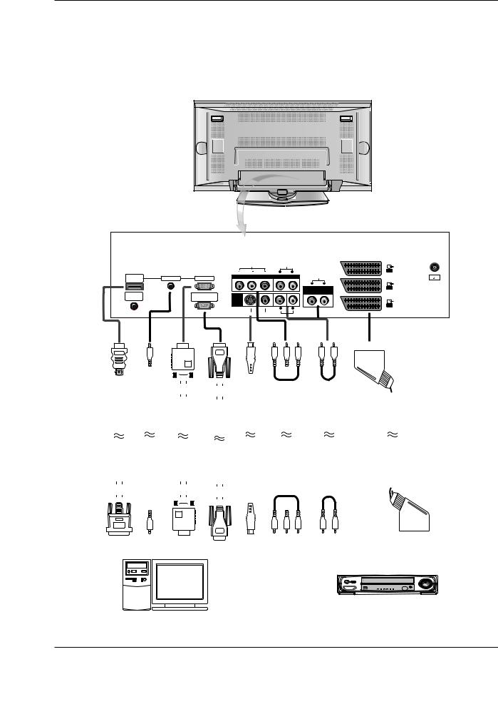
Installation
External Equipment Viewing Setups
<Back Panel> |
VIDEO |
AUDIO |
|
|
|
|
|
|
|
|
|
|
|
|
|
|
|
|
L |
R |
|
AV1 |
HDMI/ |
AUDIO INPUT |
RGB INPUT |
COMPONENT |
|
AUDIO |
Antenna |
|
DVI(VIDEO) |
|
|
|
|
|
||
|
|
|
|
|
|
|
|
|
|
|
|
|
L |
R |
|
|
|
|
|
|
VARIABLE |
AV2 |
|
REMOTE |
|
RS-232C INPUT |
|
|
AUDIO OUT |
|
|
|
|
|
|
|
|
||
CONTROL |
|
(CONTROL/SERVICE) |
AV4 |
|
|
|
|
|
|
|
|
|
|
|
AV3 |
|
|
|
|
L |
R |
|
|
|
|
|
S-VIDEO |
VIDEO |
(MONO) |
|
|
|
|
|
|
|
|
||
|
|
|
|
|
AUDIO |
|
|
|
|
|
|
|
|
|
|
|
|
|
|
|
|
|
|
|
|
|
|
|
|
|
|
|
|
|
|
|
|
|
|
|
|
|
|
|
|
|
|
|
|
|
|
|
|
|
|
|
|
|
|
|
|
|
|
|
|
|
|
|
|
|
|
|
|
|
|
|
|
|
|
|
|
|
|
|
|
|
|
|
|
|
|
|
|
|
|
|
|
|
|
|
|
|
|
|
|
|
|
|
|
|
|
|
|
|
|
|
|
|
|
|
|
|
|
|
|
|
|
|
|
|
|
|
|
|
|
|
|
|
|
|
|
|
|
|
|
|
|
|
|
|
|
|
|
|
|
|
|
|
|
|
|
|
|
|
|
|
|
|
|
|
|
|
|
|
|
|
|
|
|
|
|
|
|
|
|
|
|
|
|
|
|
|
|
|
|
|
|
|
|
|
|
|
|
|
|
|
|
|
|
|
|
|
|
|
|
|
|
|
|
|
|
|
|
|
|
|
|
|
|
|
|
|
|
|
|
|
|
|
|
|
|
|
|
|
|
|
|
|
|
|
|
|
|
|
|
|
|
|
|
|
|
|
|
|
|
|
|
|
|
|
|
|
|
|
|
|
|
|
|
|
|
|
|
|
|
|
|
|
|
|
|
|
|
|
|
|
|
|
|
|
|
|
|
|
|
|
|
|
|
|
|
|
|
|
|
|
|
|
|
|
|
|
|
|
|
|
|
|
|
|
|
|
|
|
|
|
|
|
|
|
|
|
|
|
|
|
|
|
|
|
|
|
|
|
|
|
|
|
|
|
|
|
|
|
|
|
|
|
|
|
|
|
|
|
|
|
|
|
|
|
|
|
|
|
|
|
|
|
|
|
|
|
|
|
|
|
|
|
|
|
|
|
|
|
|
|
|
|
|
|
|
|
|
|
|
|
|
|
|
|
|
|
|
|
|
|
|
|
|
|
|
|
|
|
|
|
|
|
|
|
|
|
|
|
|
|
|
|
|
|
|
|
|
|
|
|
|
|
|
|
|
|
|
|
|
|
|
|
|
|
|
|
|
|
|
|
|
|
|
|
|
|
|
|
|
|
|
|
|
|
|
|
|
|
|
|
|
|
|
|
|
|
|
|
|
|
|
|
|
|
|
|
|
|
|
|
|
|
|
|
|
|
|
|
|
|
|
|
|
|
|
|
|
|
|
|
|
|
|
|
|
|
|
|
|
|
|
|
|
|
|
|
|
|
|
|
|
|
|
|
|
|
|
|
|
|
|
|
|
|
|
|
|
|
|
|
|
|
|
|
|
|
|
|
|
|
|
|
|
|
|
|
|
|
|
|
Connection to PC |
|
|
|
|
|
|
|
|
|
|
|
|
|
|
|
|
|
|
|
|
|
|
|
|
|
|
|
|
|
|
|
|||||||||
|
|
|
|
|
|
|
|
|
|
|
|
|
|
|
|
|
|
|
|
|
|
|
|
|
|
|
|
|
|
|
|
|
|
|
||||||||||
|
|
|
|
|
|
|
|
|
|
|
|
|
|
|
|
|
|
|
|
|
|
|
|
|
|
|
|
|
|
|
|
|
|
|
||||||||||
|
|
|
|
|
|
|
|
|
|
|
|
|
|
|
|
|
|
|
|
|
|
|
|
|
|
|
|
|
|
|
|
|
|
|
||||||||||
|
|
|
|
|
|
|
|
|
|
|
|
|
|
|
|
|
|
|
|
|
|
|
|
|
|
|
|
|
|
|
|
|
|
|
||||||||||
|
|
|
|
|
|
|
|
|
|
|
|
|
|
|
|
|
|
|
|
|
|
Connection to AV equipment |
|
|||||||||||||||||||||
8 PLASMA TV

|
|
|
|
|
|
|
|
Installation |
|
|
|
|
|
|
|
|
|
|
|
Displayable Monitor Specification |
|
|
|||||||
|
|
RGB / HDMI mode |
|
|
|
|
|
||
|
|
42PX4R / 42PX5R Series |
|
50PX4R / 50PX5R Series |
|
|
|||
|
|
|
|
|
|
|
|
|
|
|
|
|
|
Vertical |
|
Resolution |
Horizontal |
Vertical |
|
|
|
|
|
Frequency(Hz) |
|
Frequency(KHz) |
Frequency(Hz) |
|
|
|
|
|
|
|
|
|
|||
|
|
|
|
|
|
|
|
|
|
|
|
|
|
70.09 |
|
640x350 |
31.468 |
70.09 |
|
|
|
|
|
85.08 |
|
37.861 |
85.08 |
|
|
|
|
|
|
|
|
|
|||
|
|
|
|
|
|
|
|
|
|
|
|
|
|
70.08 |
|
720x400 |
31.469 |
70.08 |
|
|
|
|
|
85.03 |
|
37.927 |
85.03 |
|
|
|
|
|
|
|
|
|
|||
|
|
|
|
59.94 |
|
|
31.469 |
59.94 |
|
|
|
|
|
66.66 |
|
|
35.000 |
66.66 |
|
|
|
|
|
72.80 |
|
640x480 |
37.861 |
72.80 |
|
|
|
|
|
75.00 |
|
|
37.500 |
75.00 |
|
|
|
|
|
85.00 |
|
|
43.269 |
85.00 |
|
|
|
|
|
|
|
|
|
|
|
|
|
|
|
60.00 |
|
|
31.500 |
60.00 |
|
|
|
|
|
70.00 |
|
848x480 |
37.799 |
70.00 |
|
|
|
|
|
75.00 |
|
|
39.375 |
75.00 |
|
|
|
|
|
60.00 |
|
|
31.500 |
60.00 |
|
|
|
|
|
70.00 |
|
852x480 |
37.799 |
70.00 |
|
|
|
|
|
75.00 |
|
|
39.375 |
75.00 |
|
|
|
|
|
|
|
|
|
|
|
|
|
|
|
56.25 |
|
|
35.156 |
56.25 |
|
|
|
|
|
60.31 |
|
|
37.879 |
60.31 |
|
|
|
|
|
72.18 |
|
800x600 |
48.077 |
72.18 |
|
|
|
|
|
75.00 |
|
|
46.875 |
75.00 |
|
|
|
|
|
85.06 |
|
|
53.674 |
85.06 |
|
|
|
|
|
|
|
|
|
|
|
|
|
|
|
74.55 |
|
832x624 |
49.725 |
74.55 |
|
|
|
|
|
|
|
|
|
|
|
|
|
|
|
60.00 |
|
|
48.363 |
60.00 |
|
|
|
|
|
70.06 |
|
1024x768 |
56.476 |
70.06 |
|
|
|
|
|
75.02 |
|
60.023 |
75.02 |
|
|
|
|
|
|
|
|
|
|||
|
|
|
|
85.00 |
|
|
68.677 |
85.00 |
|
|
|
|
|
|
|
|
|
|
|
|
|
|
|
60.00 |
|
1360x768 |
47.700 |
60.00 |
|
|
|
|
|
75.02 |
|
59.625 |
75.02 |
|
|
|
|
|
|
|
|
|
|||
|
|
|
|
|
|
|
|
|
|
|
|
|
|
60.00 |
|
1366x768 |
47.700 |
60.00 |
|
|
|
|
|
75.02 |
|
59.625 |
75.02 |
|
|
|
|
|
|
|
|
|
|||
|
|
|
|
|
|
|
|
|
|
|
|
|
|
60.05 |
|
|
54.348 |
60.05 |
|
|
|
|
|
70.01 |
|
1152x864 |
63.995 |
70.01 |
|
|
|
|
|
75.00 |
|
|
67.500 |
75.00 |
|
|
|
|
|
|
|
|
|
|
|
|
|
|
|
75.06 |
|
1152x870 |
68.681 |
75.06 |
|
|
|
|
|
|
|
|
|
|
|
|
|
|
|
60.00 |
|
1280x768 |
47.693 |
60.00 |
|
|
|
|
|
75.00 |
|
60.091 |
75.00 |
|
|
|
|
|
|
|
|
|
|||
|
|
|
|
|
|
|
|
|
|
|
|
|
|
60.02 |
|
1280x960 |
60.023 |
60.02 |
|
|
|
|
|
|
|
|
|
|
|
|
|
|
|
60.02 |
|
1280x1024 |
63.981 |
60.02 |
|
|
|
|
|
|
|
|
|
|
|
|
|
|
|
|
|
|
|
|
|
ENGLISH
Owner’s Manual 9
Installation
-HDMITM, the HDMI logo and High-Definition Multimedia
Interface are trademarks or registered trademarks of HDMI
Licensing.
-This set can receive the High-Definition Multimedia Interface
(HDMI) or Input of Digital Visual Interface(DVI).
-This set supports HDCP (High-bandwidth Digital Contents Protection) Protocol for the set (480p, 720p, 1080i) modes.
-When you connect to HDMI/DVI Source devices (DVD Player, STB or PC) that support AUTO HDMI/DVI Plug & Play, this sets the HDMI/DVI source devices automatically. After reading HDMI/DVI source devices, using Display Data Channel (DDC) Protocol, Extended Display Identification Data (EDID) stored in the set is used.
If HDMI/DVI Source devices do not support AUTO HDMI/DVI, the resolution is set manually.
-When Source Devices have DVI Output Connector, you must connect audio with separated cable.
(Refer to <How to connect>)
How to connect
1. When Source Devices (DVD Player or Set Top Box) support HDMI.
-If Source Devices have HDMI Output Connector, Source Devices connect to the set with HDMI Cable .(not supplied with the product).
-If Source Devices support Auto HDMI, automatically, Source
Devices divert output resolution in 1280 x 720p. But if not, refer to the reference Manual of Source Devices and select resolution manually.
-To get the best picture quality, adjust the DVD Player or Set Top Box output resolution to 1280 x 720p.
-Because HDMI sends Digital Video and Audio with one cable, there is no need for a special Audio Cable when using a HDMI Cable.
2.When Source Devices (DVD Player or Set Top Box) supports DVI.
-If Source Devices have DVI Output Connector, Source Devices connect to the set with HDMI to DVI Cable (not supplied with the product).
-If Source Devices support Auto DVI, automatically, Source Devices divert output resolution in : 1280 x 720p. But if not, refer to the reference Manual of Source Devices and select resolution manually.
-To get the best picture quality, adjust the DVD Player or Set Top Box output resolution to 1280 x 720p.
-In this case, use another cable for audio. When Source
Devices have Analog Audio Output Connector, RGB/DVI Audio Input of the set connect to Audio Cable (not supplied with the product). And then you can listen to normal Audio.
3.When PC supports DVI.
-If PC have DVI Output Connector, Source Devices connect to the set with HDMI to DVI Cable (not supplied with the product).
-To get the best picture quality, adjust the PC graphics card to 1024 x 768, 60Hz.
-Use the the set’s HDMI/DVI (VIDEO) for video connections, depending on your PC connector.
-If the graphics card on the PC does not output analog RGB and DVI simultaneously, connect only one of either RGB Input or HDMI/DVI Input to display the PC on the set.
-If he graphics card on the PC does output analog RGB and DVI simultaneously, the set to either RGB Input or HDMI/DVI Input;
(the other mode is set to Plug and Play automatically by the set.)
-Then, make the corresponding audio connections. If using a sound card, adjust the PC sound as required.
-In this case, use another cable for audio. When PC (or sound card of PC) have Analog Audio Output Connector, RGB/DVI Audio Input of the set connect to Analog Audio Cable (not supplied with the product). And then you can listen to normal Audio.
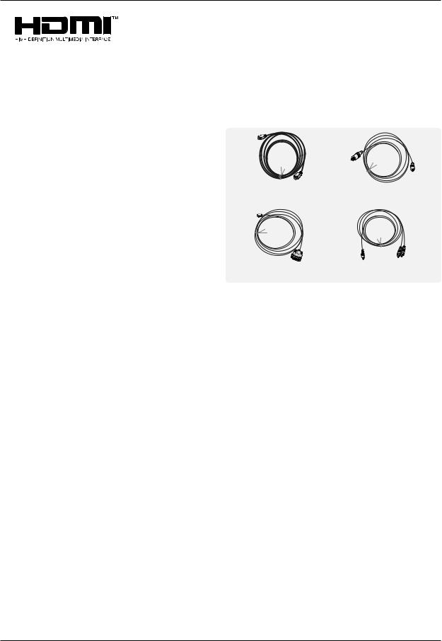
Reference
Cable sample (not supplied with the product)
HDMI Cable |
Analog Audio Cable |
|
(RCA type) |
HDMI to DVI Cable |
Analog Audio Cable |
|
(Stereo to RCA type) |
||
|
10 PLASMA TV
Accessories
LG TV
AS mark
Owner’s Manual Remote Control handset 2-Eye Bolts
Installation
ENGLISH
1.5V |
|
|
Alkaline batteries |
Power Cord |
2-Wall brackets |
Joining the set assembly to the wall to prevent the set tumbling
-Secure the set assembly by joining it to a wall by using the Eye Bolts/Wall brackets.
•If the set is to be mounted on a desk top, insert the 2 Eye-Bolts and tighten them securely in the upper holes as shown.
Install the wall brackets on the wall with 2 bolts*, (not supplied with the product), as shown.
Match the height of the Eye-Bolts and the wall brackets.
Check to be sure the Eye-Bolts and the brackets are tightened securely.
• Secure the set assembly to the wall with strong strings or wound wire cables,
(not supplied with the product), as shown.
Optional Extras
-Optional extras can be changed or modified for quality improvement. Without any notification, new optional extras can be added.
-Contract your dealer for the purchasing of these items.
|
|
|
|
|
|
|
|
|
|
|
|
|
|
|
|
|
|
|
|
|
|
|
|
|
|
|
|
|
|
|
|
|
|
|
|
|
|
|
|
|
|
|
|
|
|
|
|
|
|
|
|
|
|
|
|
|
|
|
|
|
|
|
|
|
|
|
|
|
|
|
|
|
|
|
|
|
|
|
|
|
|
|
|
|
|
|
|
|
|
|
|
|
|
|
|
|
|
|
|
|
|
|
|
|
|
|
|
|
|
|
|
|
|
|
|
|
|
|
|
|
|
|
|
|
|
|
|
|
|
|
|
|
|
|
|
|
|
|
|
|
|
|
|
|
|
|
|
|
|
|
|
|
|
|
|
|
|
|
|
|
|
|
|
|
|
|
|
|
|
|
|
|
|
|
|
|
|
|
|
|
|
|
|
|
|
|
|
|
|
|
|
|
|
|
|
|
|
|
|
|
|
|
|
|
|
|
|
|
|
|
|
|
|
|
|
|
|
|
|
|
|
|
|
Tilt wall mounting bracket |
Ceiling mounting bracket |
|
Video cables |
|
Audio cables |
||||||||||
Owner’s Manual 11

Installation
Installation Options
•The set can be installed in different ways such as on a wall, or on a desktop etc.
•Install this set only in a location where adequate ventilation is available.
Wall Mount: Horizontal Installation |
Desktop Pedestal Installation |
|
|
|
|
|||||||||||||||||||||||||
|
|
|
|
|
|
|
|
|
|
|
|
|
|
|
|
|
|
|
|
|
|
|
|
|
|
|
|
|
|
|
|
|
|
|
|
|
|
|
|
|
|
|
|
|
|
|
|
|
|
|
|
|
|
|
|
|
|
|
|
|
|
|
|
|
|
|
|
|
|
|
|
|
|
|
|
|
|
|
|
|
|
|
|
|
|
|
|
|
|
|
|
|
|
|
|
|
|
|
|
|
|
|
|
|
|
|
|
|
|
|
|
|
|
|
|
|
|
|
|
|
|
|
|
|
|
|
|
|
|
|
|
|
|
|
|
|
|
|
|
|
|
|
|
|
|
|
|
|
|
|
|
|
|
|
|
|
|
|
|
|
|
|
|
|
|
|
|
|
|
|
|
|
|
|
|
|
|
|
|
|
|
|
|
|
|
|
|
|
|
|
|
|
|
|
|
|
|
|
|
|
|
|
|
|
|
|
|
|
|
|
|
|
|
|
|
|
|
|
|
|
|
|
|
|
|
|
|
|
|
|
|
|
|
|
|
|
|
|
|
|
|
|
|
|
|
|
|
|
|
|
|
|
|
|
|
|
|
|
|
|
|
|
|
|
|
|
|
|
|
|
|
|
|
|
|
|
|
|
|
|
|
|
|
|
|
|
|
|
|
|
|
|
|
|
|
|
|
|
|
|
|
|
|
|
|
|
|
|
|
|
|
|
|
|
|
|
|
|
|
|
|
|
|
|
|
|
|
|
|
|
|
|
|
|
|
|
|
|
|
|
|
|
|
|
|
|
|
|
|
|
|
|
|
|
|
|
|
|
|
|
|
|
|
|
|
|
|
|
|
|
|
|
|
|
|
|
|
|
|
|
|
|
|
|
|
|
|
|
|
|
|
|
|
|
|
|
|
|
|
|
|
|
|
|
|
|
|
|
|
|
|
|
|
|
|
|
|
|
|
|
|
|
|
|
|
|
|
|
|
|
|
|
|
|
|
|
|
|
|
|
|
|
|
|
|
|
|
|
|
|
|
|
|
|
|
|
|
|
|
|
|
|
|
|
•The set can be installed on a wall as shown above. (For further information, refer to the optional ‘Wall Mounting Bracket Installation and Setup Guide’.)
• The set can be mounted on a desk as shown above.
To Mount on a Wall
Wall mount minimum allowable clearances for adequate ventilation.
|
10cm |
|
3cm |
10cm |
10cm |
|
10cm |
To Install on a Desktop
Pedestal mount minimum allowable clearances for adequate ventilation.
Swivel function (option)
• After installing the set, you can adjust the set manually to the left or right direction by 20 degrees to suit your viewing position.
Note : Before adjusting the angle, you must loosen (to the left) the shaft bolt on the middle of stand’s back. And when the stand is level with set, you must close (to the right) the shaft bolt to set the hole.
12 PLASMA TV
 Loading...