


 Loading...
LevelOne
WAP-0006/0009
11g Wireless AP
User Manual
V1.0-0609
CHAPTER 1 |
INTRODUCTION ................................................................... |
1 |
||
1.1 |
PACKAGE CONTENTS .......................................................................................................................................... |
2 |
||
1.2 |
FEATURES........................................................................................................................................................... |
2 |
||
1.3 |
SPECIFICATIONS.................................................................................................................................................. |
2 |
||
1.4 |
PHYSICAL .....................................................................................................................................DESCRIPTION |
3 |
||
CHAPTER 2 .............................................. |
HARDWARE INSTALLATION |
5 |
||
CHAPTER 3 ......... |
WIRELESS LAN ACCESS POINT CONFIGURATION |
6 |
||
3.1 |
GETTING ..............................................................................................................................................STARTED |
6 |
||
3.2 |
CONFIGURING ....................................................................................................................THE ACCESS POINT |
10 |
||
|
3.2.1 |
Status ......................................................................................................................and Information |
11 |
|
|
3.2.2 |
Wireless ..................................................................................................................................Setting |
11 |
|
|
3.2.3 |
Advanced ...............................................................................................................................Setting |
23 |
|
|
3.2.4 |
AP .........................................................................................................................................Security |
25 |
|
|
3.2.5 |
MAC .......................................................................................................................Address Filtering |
34 |
|
|
3.2.6 |
System ......................................................................................................................................Utility |
36 |
|
|
3.2.7 |
Configuration ..............................................................................................................................Tool |
40 |
|
|
3.2.8 |
Firmware .............................................................................................................................Upgrade |
41 |
|
|
3.2.9 |
Reset.................................................................................................................................................... |
42 |
|
CHAPTER 4 ........................................................ |
TROUBLESHOOTING |
43 |
||

Introduction
Chapter 1 |
Introduction |
LevelOne WAP-0006/0009 is an access point for IEEE 802.11g/b 2.4GHz wireless network. User can use this access point to build up a wireless LAN. Any wireless LAN station can join the wireless network by using the “Infrastructure Mode”.
The product supports WEP, WPA, WPA2, ESSID and MAC address filter functions to consolidate the wireless network security. With ESSID authentication, WPA2 encryption and MAC address filtering user can prevent unauthorized wireless stations from accessing user’s wireless network.
The product’s dipole antenna is detachable by connecting to a RP-SMA connector. Users can install a high gain antenna to the connector for better network link quality so that user can build wireless network with more flexibility.
This product provides easy to use user interface and allows users to configuring from web browser. Also it integrates DHCP server to provide multiple wireless and wired users to get their IP address automatically.
With the versatile of features, this product is the best choice for user to integrate user’s wireless and wired network seamlessly.
1

Introduction
1.1Package Contents
The Access Point includes the following items:
yWAP-0006/0009
yPower Adapter (WAP-0006 Only)
yDipole Antenna
yCD Manual
yQuick Installation Guide
1.2Features
yComplies with the IEEE 802.11b/g (DSSS) 2.4GHz specification.
yCompliant with IEEE802.3af POE PD(Power Device) standard (WAP-0009 Only)
yHigh data rate 54Mbps network speed.
ySeamlessly integrate wireless and wired Ethernet LAN networks.
yAuto rate fallback in case of obstacles or interferences.
yProvide 64/128-bit WEP and WPA Data Encryption function to protect the wireless data transmissions.
yBuilt-in DHCP server supports auto IP addresses assignment.
ySupports Web-based configuration.
1.3Specifications
yStandards: IEEE 802.11b/g (Wireless), IEEE 802.3 (Wired)
yData Rate: 54/48/36/24/18/12/11/9/6/5.5/2/1Mbps auto fallback
ySecurity Encryption: 64/128-bit WEP/
WPA(802.1x, TKIP)
WPA2(AES)
yFrequency Band: 2.400~2.4835GHz (Industrial Scientific Medical Band)
yModulation: CCK@11/5.5Mbps, DQPSK@2Mbps and DBPSK@1Mbps
yRadio Technology: Direct Sequence Spread Spectrum (DSSS)
yAntenna: External detachable dipole antenna (with RP-SMA connector)
yConnectors: 10/100Mbps RJ-45 x 1
2

Introduction
yPower: 12VDC, 0.5A
yTransmit Power: 15dBm (Typical)
yLEDs: Power, LAN Link/Activity, Wireless Activity
yDimension: 30(H) x 127(W) x 96(D) mm
yTemperature:
Operating: 32~131°F (0~55°C)
Storage: -4~158°F(-20~70°C)
yHumidity: 10-90% (Noncondensing)
yCertification: FCC, CE
1.4Physical Description
Front Panel
On the Access Point’s front panel there are LED lights that inform user of the Access Point’s current status. Below is an explanation of each LED.
LED |
Color |
Status |
Description |
|
Power |
Green |
Lit |
Power is supplied. |
|
Off |
No Power. |
|||
|
|
|||
Wireless |
Green |
Flash |
Antenna is transmitting or receiving data. |
|
Activity |
Off |
Antenna is not transmitting or receiving data. |
||
|
||||
LAN |
|
On |
A valid link is established. |
|
Green |
Flash |
It is transmitting or receiving data. |
||
Link/Activity |
||||
|
Off |
No link is established. |
||
|
|
3
Introduction
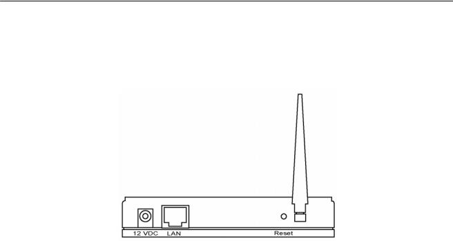
Back Panel
Access Point’s connection ports are located on the back panel. Below is the description of each connection port.
yAntenna Connector
This round connection is standard Reverse SMA connector where any antennas with Reverse SMA connector can connect to the Access Point.
yDC Adapter Port
Insert the power jack of the power adapter into this port.
yLAN Port
The Access Point’s LAN port is where user connects to user’s LAN’s network devices.
yReset
The Reset button allows user to do one of two things.
1)If problems occur with user’s Access Point, press the reset button with a pencil tip (for less than 4 seconds) and the Access Point will re-boot itself, keeping user’s original configurations.
2)If problems persist or user experience extreme problems or user forgot user’s password, press the reset button for longer than 4 seconds and the Access Point will reset itself to the factory default settings (warning: user’s original configurations will be replaced with the factory default settings).
4

Wireless LAN Access Point Connection
Chapter 2 Hardware Installation
1.Locate an optimum location for the Wireless LAN Access Point.
The best location for user’s Access Point is usually at the center of user’s wireless network, with line of sight to all of user’s mobile stations.
2.Connect the Wireless LAN Access Point to user’s router, hub or switch.
Connect one end of standard UTP cable to the Access Point’s LAN Port and connect the other end of the cable to a switch, a router or a hub. The Access Point will then be connected to user’s existed wired LAN Network.
3.Connect the DC Power Adapter to the Wireless LAN Access Point’s Power Socket. (WAP-0006)
Only use the power adapter supplied with the Access Point. Using a different adapter may damage the product.
4.Connect the Wireless LAN Access Point to your POE adapter, router, hub or switch. (WAP-0009 Only)
Connect one end of standard UTP cable to the Access Point’s LAN Port and connect the other end of the cable to a powered Ethernet port on POE switch, POE router, POE hub, or POE adapter. The Access Point will then power ON and connected to your existed wired LAN Network.
The Hardware Installation is complete.
5

Wireless LAN Access Point Configuration
Chapter 3 Wireless LAN Access Point
Configuration
3.1Getting Started
This Access Point provides web-based configuration tool allowing user to configure from wired or wireless stations. Follow the instructions below to get started configuration.
From Wired Station
1. Make sure user’s wired station is in the same subnet with the Access Point. The default IP Address and Sub Mask of the Access Point is:
Default IP Address: 192.168.2.1
Default Subnet: 255.255.255.0
Configure user’s PC to be in the same subnet with the Access Point.
1a) Windows 98SE/ME
1.Click the Start button and select Settings, then click Control Panel. The Control Panel window will appear.
2.Double-click Network icon. The Network window will appear.
3.Check user’s list of Network Components. If TCP/IP is not installed, click the Add button to install it now. If TCP/IP is installed, go to step 6.
4.In the Network Component Type dialog box, select Protocol and click Add button.
5.In the Select Network Protocol dialog box, select Microsoft and TCP/IP and then click the
OK button to start installing the TCP/IP protocol. User may need user’s Windows CD to complete the installation.
6.After installing TCP/IP, go back to the Network dialog box. Select TCP/IP from the list of
Network Components and then click the Properties button.
7.Check each of the tabs and verify the following settings:
•Bindings: Check Client for Microsoft Networks and File and printer sharing for Microsoft Networks.
•Gateway: All fields are blank.
•DNS Configuration: Select Disable DNS.
•WINS Configuration: Select Disable WINS Resolution.
6
Wireless LAN Access Point Configuration
•IP Address: Select Specify an IP Address. Specify the IP Address and Subnet Mask as following example.
9 IP Address: 192.168.2.3 (any IP address within 192.168.2.2~192.168.2.254 is available, do not setup 192.168.2.1)
9 Subnet Mask: 255.255.255.0
8.Reboot the PC. User’s PC will now have the IP Address user specified.
1b) Windows XP
1.Click the Start button and select Settings, then click Network Connections. The Network Connections window will appear.
2.Double-click Local Area Connection icon. The Local Area Connection window will appear.
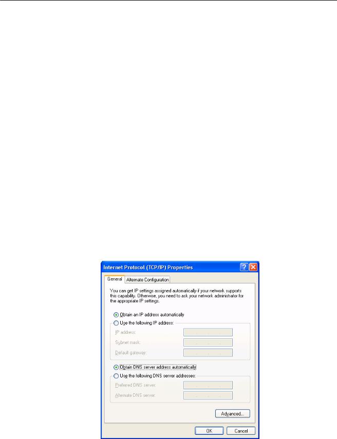
3.Check user’s list of Network Components. User should see Internet Protocol [TCP/IP] on user’s list. Select it and click the Properties button.
4.In the Internet Protocol (TCP/IP) Properties window, select Obtain an IP address automatically and Obtain DNS server address automatically as shown on the following screen.
5.Click OK to confirm the setting. User’s PC will now obtain an IP address automatically from user’s Broadband Router’s DHCP server.
Note: Please make sure that the Broadband router’s DHCP server is the only DHCP server available on user’s LAN.
7

Wireless LAN Access Point Configuration
Once user has configured user’s PC to obtain an IP address automatically, please proceed to
Step 3.
1c) Windows 2000
1.Click the Start button and select Settings, then click Control Panel. The Control Panel window will appear.
2.Double-click Network and Dial-up Connections icon. In the Network and Dial-up Connection window, double-click Local Area Connection icon. The Local Area Connection window will appear.
3.In the Local Area Connection window, click the Properties button.
4.Check user’s list of Network Components. User should see Internet Protocol [TCP/IP] on user’s list. Select it and click the Properties button.
5.In the Internet Protocol (TCP/IP) Properties window, select Use the following IP address and specify the IP Address and Subnet mask as following.
9 IP Address: 192.168.2.3 (any IP address within 192.168.2.2~192.168.2.254 is available, do not setup 192.168.2.1)
9 Subnet Mask: 255.255.255.0
6.Click OK to confirm the setting. User’s PC will now have the IP Address user specified.
2.Enter 192.168.2.1 from Web Browser to get into the Access Point’s configuration tool.
3.A screen will be popped up and request user to enter user name and password. The default user name and password is as follows.
User Name: Admin Password: 1234
Enter the default user name and password, then press OK button directly.
8
Wireless LAN Access Point Configuration
4. User can start configuring the Access Point.
From Wireless Station
1.Make sure user’s wireless station is in the same subnet with the Access Point. Please refer to the step 1 above for configuring the IP Address and Sub Mask of the wireless station.
2.Connect to the Access Point.
The Access Point’s default ESSID is “default” and the WEP Encryption function is disabled. Make sure user’s wireless station is using the same ESSID as the Access Point and associate user’s wireless station to the Access Point.
3.Enter 192.168.2.1 from Web Browser to get into the Access Point’s configuration tool.
4.Enter the user name and password and then press OK button and user are available to configure the Access Point now.
9
Wireless LAN Access Point Configuration
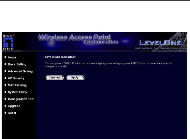
3.2Configuring the Access Point
Every time when user has finished modifying a setting page and click “Apply” button, this page will pop-up. The settings have been successfully saved but will not take effect immediately. User has to restart the access point to make the new settings take effect.
User can click “CONTINUE” button to continue other settings. User also can click “APPLY” to restart the system and make the settings take effect.
10

Wireless LAN Access Point Configuration
3.2.1 Status and Information
On this screen, user can see the general information of the Access Point including Alias
Name, Firmware Version, ESSID, Channel Number, Status, IP Address, MAC Address, etc.
3.2.2 Wireless Setting
This Access Point supports AP, Station, Bridge, WDS and Universal Repeater modes.
“AP Mode” provides pure access point function. The simplest way to build up a wireless
LAN is to use “AP Mode”.
“Station Mode” is used to let a network device with only wired Ethernet function to have wireless LAN communication capability. It provides both Ad Hoc and Infrastructure modes for the “Station Mode”. With “Station-Ad Hoc mode”, it can let user’s network device join a wireless LAN with peer-to-peer communication. With “AP-Client mode”, it can let user’s network device join a wireless LAN through an access point.
11

Wireless LAN Access Point Configuration
“AP Bridge Mode” provides the function to bridge more than two wired Ethernet networks together by wireless LAN. User can use two access points with “AP Bridge-Point to Point mode” to bridge two wired Ethernet networks together. If user want to bridge more than two wired Ethernet networks together, user have to use enough access points with “AP
Bridge-Point to Multi-Point mode”.
An access point with “AP Bridge-Point to Point mode” or “AP Bridge-Point to MultiPoint mode” can only be used to bridge wired Ethernet networks together. It can’t accept connection from other wireless station at the same time. If user want an access point to bridge wired Ethernet network and provide connection service for other wireless station at the same time, user have to set the access point to “AP Bridge-WDS mode”.
Simply speaking, “AP Bridge-WDS mode” function is the combination of “AP mode” and
“AP Bridge-Point to Multi-Point mode”. “
“Universal Repeater Mode” provides the function to act as AP client and AP at the same time. It can use AP client function to connect to a Root AP and use AP function to service all wireless stations within its coverage. All the stations within the coverage of this access point can be bridged to the Root AP. “Universal Repeater Mode” is very convenient to extend the coverage of user’s wireless network.
12

Wireless LAN Access Point Configuration
AP mode setting page:
Station-Ad Hoc mode setting page:
13
Loading...