


 Loading...
LDCDS−EL100
.LRN
Ä.LRNä
Operating Instructions
HMI with Windowsâ CE
EL 1xx ECO, EL 1xx ECO PLC, EL 1xx CAN, EL 1xx PLC, EL 1xx MPI
HMI for visualisation / with control technology
l

,Please read these instructions before you start working! Follow the enclosed safety instructions.

Contents i
1 |
About this documentation . . . . . . . . . . . . . . . . . . . . . . . . . . . . . . . . . . . . . . . . . . . . . . . . . . |
6 |
||
|
1.1 |
Validity information . . . . . . . . . . . . . . . . . . . . . . . . . . . . . . . . . . . . . . . . . . . . . . . . . . |
6 |
|
|
1.2 |
Target group . . . . . . . . . . . . . . . . . . . . . . . . . . . . . . . . . . . . . . . . . . . . . . . . . . . . . . . . |
6 |
|
|
1.3 |
Document history . . . . . . . . . . . . . . . . . . . . . . . . . . . . . . . . . . . . . . . . . . . . . . . . . . . . |
7 |
|
|
1.4 |
Terminology used . . . . . . . . . . . . . . . . . . . . . . . . . . . . . . . . . . . . . . . . . . . . . . . . . . . . |
7 |
|
|
1.5 |
Conventions used . . . . . . . . . . . . . . . . . . . . . . . . . . . . . . . . . . . . . . . . . . . . . . . . . . . . |
8 |
|
|
1.6 |
Notes used . . . . . . . . . . . . . . . . . . . . . . . . . . . . . . . . . . . . . . . . . . . . . . . . . . . . . . . . . . |
9 |
|
2 |
Safety instructions . . . . . . . . . . . . . . . . . . . . . . . . . . . . . . . . . . . . . . . . . . . . . . . . . . . . . . . . . |
10 |
||
|
2.1 |
General safety instructions . . . . . . . . . . . . . . . . . . . . . . . . . . . . . . . . . . . . . . . . . . . . . |
10 |
|
|
2.2 |
Product−specific safety instructions . . . . . . . . . . . . . . . . . . . . . . . . . . . . . . . . . . . . . |
12 |
|
|
2.3 |
Safety instructions for the installation according to UL . . . . . . . . . . . . . . . . . . . . . |
13 |
|
3 |
Product description . . . . . . . . . . . . . . . . . . . . . . . . . . . . . . . . . . . . . . . . . . . . . . . . . . . . . . . . |
15 |
||
|
3.1 |
Application as directed . . . . . . . . . . . . . . . . . . . . . . . . . . . . . . . . . . . . . . . . . . . . . . . |
15 |
|
|
3.2 |
Scope of supply . . . . . . . . . . . . . . . . . . . . . . . . . . . . . . . . . . . . . . . . . . . . . . . . . . . . . . |
16 |
|
|
3.3 |
Overview . . . . . . . . . . . . . . . . . . . . . . . . . . . . . . . . . . . . . . . . . . . . . . . . . . . . . . . . . . . . |
16 |
|
|
|
3.3.1 |
EL 1xx CAN/PLC/MPI . . . . . . . . . . . . . . . . . . . . . . . . . . . . . . . . . . . . . . . . . . |
16 |
|
|
3.3.2 |
EL 1xx ECO (PLC) . . . . . . . . . . . . . . . . . . . . . . . . . . . . . . . . . . . . . . . . . . . . . . |
17 |
4 |
Technical data |
. . . . . . . . . . . . . . . . . . . . . . . . . . . . . . . . . . . . . . . . . . . . . . . . . . . . . . . . . . . . |
18 |
|
|
4.1 |
General data and operating conditions . . . . . . . . . . . . . . . . . . . . . . . . . . . . . . . . . |
18 |
|
|
4.2 |
Electrical data . . . . . . . . . . . . . . . . . . . . . . . . . . . . . . . . . . . . . . . . . . . . . . . . . . . . . . . . |
19 |
|
|
|
4.2.1 |
EL 1xx CAN/PLC/MPI . . . . . . . . . . . . . . . . . . . . . . . . . . . . . . . . . . . . . . . . . . |
19 |
|
|
4.2.2 |
EL 1xx ECO (PLC) . . . . . . . . . . . . . . . . . . . . . . . . . . . . . . . . . . . . . . . . . . . . . . |
22 |
|
4.3 |
Mechanical data . . . . . . . . . . . . . . . . . . . . . . . . . . . . . . . . . . . . . . . . . . . . . . . . . . . . |
24 |
|
|
|
4.3.1 |
EL 1xx CAN/PLC/MPI . . . . . . . . . . . . . . . . . . . . . . . . . . . . . . . . . . . . . . . . . . |
24 |
|
|
4.3.2 |
EL 1xx ECO (PLC) . . . . . . . . . . . . . . . . . . . . . . . . . . . . . . . . . . . . . . . . . . . . . . |
25 |
5 |
Mechanical installation . . . . . . . . . . . . . . . . . . . . . . . . . . . . . . . . . . . . . . . . . . . . . . . . . . . . . |
26 |
||
|
5.1 |
Important notes . . . . . . . . . . . . . . . . . . . . . . . . . . . . . . . . . . . . . . . . . . . . . . . . . . . . . . |
26 |
|
|
5.2 |
Mounting steps . . . . . . . . . . . . . . . . . . . . . . . . . . . . . . . . . . . . . . . . . . . . . . . . . . . . . . |
27 |
|
6 |
Electrical installation . . . . . . . . . . . . . . . . . . . . . . . . . . . . . . . . . . . . . . . . . . . . . . . . . . . . . . . |
28 |
||
|
6.1 |
Important notes . . . . . . . . . . . . . . . . . . . . . . . . . . . . . . . . . . . . . . . . . . . . . . . . . . . . . . |
28 |
|
|
6.2 |
Wiring according to EMC . . . . . . . . . . . . . . . . . . . . . . . . . . . . . . . . . . . . . . . . . . . . . . |
29 |
|
|
6.3 |
Wiring . |
. . . . . . . . . . . . . . . . . . . . . . . . . . . . . . . . . . . . . . . . . . . . . . . . . . . . . . . . . . . . . |
30 |
|
|
6.3.1 |
EL 1xx CAN/PLC/MPI . . . . . . . . . . . . . . . . . . . . . . . . . . . . . . . . . . . . . . . . . . |
30 |
|
|
6.3.2 |
EL 1xx ECO (PLC) . . . . . . . . . . . . . . . . . . . . . . . . . . . . . . . . . . . . . . . . . . . . . . |
34 |
LDCDS−EL100 EN 9.0
l 3

i Contents
7 |
Commissioning . . . . . . . . . . . . . . . . . . . . . . . . . . . . . . . . . . . . . . . . . . . . . . . . . . . . . . . . . . . |
37 |
||
|
7.1 |
Connecting external devices . . . . . . . . . . . . . . . . . . . . . . . . . . . . . . . . . . . . . . . . . . . |
37 |
|
|
7.2 |
Initial switch−on . . . . . . . . . . . . . . . . . . . . . . . . . . . . . . . . . . . . . . . . . . . . . . . . . . . . . . |
38 |
|
|
7.3 |
Establish Ethernet connection . . . . . . . . . . . . . . . . . . . . . . . . . . . . . . . . . . . . . . . . . . |
38 |
|
|
|
7.3.1 |
Configure Ethernet interface . . . . . . . . . . . . . . . . . . . . . . . . . . . . . . . . . . . . |
39 |
|
|
7.3.2 |
Activate communication between EL 1xx and VisiWinNetâ Smart . . . |
40 |
|
7.4 |
Establish CAN fieldbus connection . . . . . . . . . . . . . . . . . . . . . . . . . . . . . . . . . . . . . . |
41 |
|
|
|
7.4.1 |
Configure CAN interface . . . . . . . . . . . . . . . . . . . . . . . . . . . . . . . . . . . . . . . |
41 |
|
7.5 |
Establish MPI connection . . . . . . . . . . . . . . . . . . . . . . . . . . . . . . . . . . . . . . . . . . . . . . |
42 |
|
|
7.6 |
UPS functionality . . . . . . . . . . . . . . . . . . . . . . . . . . . . . . . . . . . . . . . . . . . . . . . . . . . . . |
43 |
|
|
7.7 |
Installing fonts . . . . . . . . . . . . . . . . . . . . . . . . . . . . . . . . . . . . . . . . . . . . . . . . . . . . . . . |
44 |
|
8 |
Operation . . . |
. . . . . . . . . . . . . . . . . . . . . . . . . . . . . . . . . . . . . . . . . . . . . . . . . . . . . . . . . . . . . |
45 |
|
|
8.1 |
Operating system components . . . . . . . . . . . . . . . . . . . . . . . . . . . . . . . . . . . . . . . . . |
45 |
|
|
8.2 |
Control Panel Applets . . . . . . . . . . . . . . . . . . . . . . . . . . . . . . . . . . . . . . . . . . . . . . . . . |
46 |
|
|
|
8.2.1 |
StartUp . . . . . . . . . . . . . . . . . . . . . . . . . . . . . . . . . . . . . . . . . . . . . . . . . . . . . |
47 |
|
|
8.2.2 |
Registry . . . . . . . . . . . . . . . . . . . . . . . . . . . . . . . . . . . . . . . . . . . . . . . . . . . . . |
48 |
|
|
8.2.3 |
VisiWinNETâ . . . . . . . . . . . . . . . . . . . . . . . . . . . . . . . . . . . . . . . . . . . . . . . . |
49 |
|
|
8.2.4 |
Display . . . . . . . . . . . . . . . . . . . . . . . . . . . . . . . . . . . . . . . . . . . . . . . . . . . . . . |
49 |
|
|
8.2.5 |
Server . . . . . . . . . . . . . . . . . . . . . . . . . . . . . . . . . . . . . . . . . . . . . . . . . . . . . . . |
50 |
|
|
8.2.6 |
Fieldbus . . . . . . . . . . . . . . . . . . . . . . . . . . . . . . . . . . . . . . . . . . . . . . . . . . . . . |
50 |
|
|
8.2.7 |
MPI Configuration . . . . . . . . . . . . . . . . . . . . . . . . . . . . . . . . . . . . . . . . . . . . |
51 |
|
|
8.2.8 |
CAN Gateway . . . . . . . . . . . . . . . . . . . . . . . . . . . . . . . . . . . . . . . . . . . . . . . |
51 |
|
8.3 |
Creating a PLC sample program . . . . . . . . . . . . . . . . . . . . . . . . . . . . . . . . . . . . . . . . |
55 |
|
|
|
8.3.1 |
General information on PLC programming . . . . . . . . . . . . . . . . . . . . . . . |
55 |
|
|
8.3.2 |
Start PLC Designer . . . . . . . . . . . . . . . . . . . . . . . . . . . . . . . . . . . . . . . . . . . . |
56 |
|
|
8.3.3 |
Create PLC program . . . . . . . . . . . . . . . . . . . . . . . . . . . . . . . . . . . . . . . . . . . |
56 |
|
|
8.3.4 |
Create sym file . . . . . . . . . . . . . . . . . . . . . . . . . . . . . . . . . . . . . . . . . . . . . . . |
60 |
|
|
8.3.5 |
Transfer program to HMI . . . . . . . . . . . . . . . . . . . . . . . . . . . . . . . . . . . . . . |
62 |
|
|
8.3.6 |
Start program on HMI . . . . . . . . . . . . . . . . . . . . . . . . . . . . . . . . . . . . . . . . . |
64 |
|
|
8.3.7 |
Build up CAN communication with distributed I/O module . . . . . . . . . |
64 |
|
8.4 |
Access EL 1xx via server functionality . . . . . . . . . . . . . . . . . . . . . . . . . . . . . . . . . . . . |
71 |
|
|
|
8.4.1 |
Enable Server Access . . . . . . . . . . . . . . . . . . . . . . . . . . . . . . . . . . . . . . . . . |
72 |
|
|
8.4.2 |
FTP Server − Transmit Data . . . . . . . . . . . . . . . . . . . . . . . . . . . . . . . . . . . . . |
74 |
|
|
8.4.3 |
Web Server (SysAdmin) − Manage Processes, Files, Registry . . . . . . . . . . |
74 |
|
|
8.4.4 |
Telnet Server − Manage files at the Windows Command Prompt . . . . . |
75 |
|
|
8.4.5 |
VNC−Server − Operate the EL 1xx by remote control via Internet or LAN |
76 |
|
|
8.4.6 |
RAS Server − Operate your EL 1xx by remote control via telephone line |
77 |
4 |
l |
LDCDS−EL100 EN 9.0

Contents i
|
8.5 |
Communicating via the CAN gateway function . . . . . . . . . . . . . . . . . . . . . . . . . . . . |
78 |
|
|
|
8.5.1 |
Important notes . . . . . . . . . . . . . . . . . . . . . . . . . . . . . . . . . . . . . . . . . . . . . . |
78 |
|
|
8.5.2 |
Establishing communication using the system bus configurator . . . . . . |
78 |
|
|
8.5.3 |
Establishing communication using the Global Drive Control (GDC) . . . |
82 |
|
|
8.5.4 |
Establishing communication using the L−force Engineer . . . . . . . . . . . . |
84 |
|
|
8.5.5 |
Establishing communication using the Drive PLC Developer |
|
|
|
|
Studio (DDS) . . . . . . . . . . . . . . . . . . . . . . . . . . . . . . . . . . . . . . . . . . . . . . . . . |
87 |
9 |
Maintenance |
. . . . . . . . . . . . . . . . . . . . . . . . . . . . . . . . . . . . . . . . . . . . . . . . . . . . . . . . . . . . . |
89 |
|
|
9.1 |
General notes . . . . . . . . . . . . . . . . . . . . . . . . . . . . . . . . . . . . . . . . . . . . . . . . . . . . . . . |
89 |
|
|
9.2 |
Regular checks . . . . . . . . . . . . . . . . . . . . . . . . . . . . . . . . . . . . . . . . . . . . . . . . . . . . . . . |
89 |
|
|
9.3 |
Cleaning |
. . . . . . . . . . . . . . . . . . . . . . . . . . . . . . . . . . . . . . . . . . . . . . . . . . . . . . . . . . . . |
90 |
|
9.4 |
Battery replacement . . . . . . . . . . . . . . . . . . . . . . . . . . . . . . . . . . . . . . . . . . . . . . . . . . |
91 |
|
10 |
Index |
. . . . . . . |
. . . . . . . . . . . . . . . . . . . . . . . . . . . . . . . . . . . . . . . . . . . . . . . . . . . . . . . . . . . . . |
93 |
LDCDS−EL100 EN 9.0
l 5

1 |
About this documentation |
|
Validity information |
|
|
1 |
0Fig. 0Tab. 0 |
About this documentation |
1.1Validity information
These instructions are valid for
HMI with CAN interface |
HMI with CAN interface, integrated |
HMI with MPI interface |
|
|
PLC and UPS |
|
|
EL 103 ECO |
EL 103 ECO PLC |
− |
|
|
|
|
|
EL 105M CAN |
EL 105m PLC |
EL 105M MPI |
|
|
|
|
|
EL 105 CAN |
EL 105 PLC |
EL 105 MPI |
|
|
|
|
|
EL 106 CAN |
EL 106 PLC |
EL 106 MPI |
|
|
|
|
|
EL 108 CAN |
EL 108 PLC |
EL 108 MPI |
|
|
|
|
|
EL 110 CAN |
EL 110 PLC |
EL 110 MPI |
|
|
|
|
|
EL 110s CAN |
EL 110s PLC |
EL 110s MPI |
|
The nameplate is on the back of the device.
1.2Target group
This documentation is directed at qualified skilled personnel according to IEC 60364.
Qualified skilled personnel are persons who have the required qualifications to carry out all activities involved in installing, mounting, commissioning, and operating the product.
6 |
l |
LDCDS−EL100 EN 9.0

About this documentation |
1 |
Document history
1.3Document history
Material number |
Version |
|
|
Description |
|
.LRN |
9.0 |
11/2013 |
TD29 |
Safety instructions for the installation according to |
|
|
|
|
|
UL added and other revisions |
|
|
|
|
|
|
|
13398591 |
8.0 |
01/2012 |
TD29 |
New chapter "Install fonts" |
|
|
|
|
|
|
|
13349601 |
7.1 |
07/2011 |
TD29 |
Pin assignment SUB−D plug corrected |
|
|
|
|
|
|
|
13349601 |
7.0 |
06/2011 |
TD29 |
UL approval and other revisions |
|
|
|
|
|
|
|
13346004 |
6.0 |
08/2010 |
TD29 |
Corrected CAN connection drawing for EL 103 ECO |
|
|
|
|
|
|
|
13327978 |
5.0 |
05/2010 |
TD29 |
Amended by description of type EL 103 ECO; |
|
|
|
|
|
description of type EL 112 deleted; adapted BA |
|
|
|
|
|
according to the new specifications regarding the |
|
|
|
|
|
Lenze classification and the new specifications of |
|
|
|
|
|
the units of measurement regulation |
|
|
|
|
|
|
|
13273430 |
4.0 |
01/2009 |
TD29 |
Amended by description of type EL 112 |
|
|
|
|
|
|
|
13236340 |
3.0 |
04/2008 |
TD29 |
Description of type EL 110s and all types with |
|
|
|
|
|
integrated PLC has been added |
|
|
|
|
|
|
|
13227672 |
2.0 |
11/2007 |
TD29 |
The "Commissioning" chapter has been expanded by |
|
|
|
|
|
descriptions on server functionalities |
|
|
|
|
|
|
|
13200039 |
1.0 |
03/2007 |
TD29 |
First edition |
|
I Tip!
Information and auxiliary devices related to the Lenze products can be found in the download area at
http://www.Lenze.com
1.4Terminology used
Term |
In the following text used for |
|
EL 1xx |
HMI of the EL 100 or EL 100 ECO series |
|
|
|
|
HMI |
Human Machine Interface |
|
|
|
|
MPI |
Interface for the SIMATIC S7 automation system from Siemens AG |
|
|
|
|
SD/SDHC card |
Memory card in the SD/SDHC format |
|
|
|
|
Touchscreen |
Touch screen terminal |
|
LDCDS−EL100 EN 9.0
l 7

1 |
About this documentation |
|
Conventions used |
|
|
1.5 |
Conventions used |
|
|
|
|
|
|
|
|
|
|
|
Type of information |
Identification |
Examples/notes |
|
|
|
Spelling of numbers |
|
|
|
|
|
|
|
|
|
|
|
|
Decimal separator |
Point |
In general, the decimal point is used. |
|
|
|
|
|
For instance: 1234.56 |
|
|
|
|
|
|
|
|
Text |
|
|
|
|
|
|
|
|
|
|
|
|
Program name |
» « |
PC software |
|
|
|
|
|
For example: »Engineer«, »Global Drive |
|
|
|
|
|
Control« (GDC) |
|
|
|
|
|
|
|
|
Icons |
|
|
|
|
|
|
|
|
|
|
|
|
Page reference |
^ |
Reference to another page with additional |
|
|
|
|
|
information |
|
|
|
|
|
For instance: ^16 = see page 16 |
|
|
|
|
|
|
|
|
|
Documentation reference |
, |
Reference to another documentation with |
|
|
|
|
|
additional information |
|
|
|
|
|
For example: ,EDKxxx = see |
|
|
|
|
|
documentation EDKxxx |
|
8 |
l |
LDCDS−EL100 EN 9.0

About this documentation |
1 |
Notes used
1.6Notes used
The following pictographs and signal words are used in this documentation to indicate dangers and important information:
Safety instructions
Structure of safety instructions:
} Danger!
(characterises the type and severity of danger)
Note
(describes the danger and gives information about how to prevent dangerous situations)
Pictograph and signal word |
Meaning |
|
{ Danger! |
Danger of personal injury through dangerous electrical voltage. |
|
Reference to an imminent danger that may result in death or |
|
|
serious personal injury if the corresponding measures are not |
|
|
|
taken. |
|
|
|
|
} Danger! |
Danger of personal injury through a general source of danger. |
|
Reference to an imminent danger that may result in death or |
|
|
serious personal injury if the corresponding measures are not |
|
|
|
taken. |
|
|
|
|
( Stop! |
Danger of property damage. |
|
Reference to a possible danger that may result in property |
|
|
damage if the corresponding measures are not taken. |
|
|
|
|
|
Application notes |
|
|
|
|
|
Pictograph and signal word |
Meaning |
|
) Note! |
Important note to ensure troublefree operation |
|
|
|
|
|
|
|
I Tip! |
Useful tip for simple handling |
|
|
|
|
|
|
|
, |
Reference to another documentation |
|
|
|
|
|
|
|
Special safety instructions and application notes |
|
|
|
|
|
Pictograph and signal word |
Meaning |
|
|
|
|
JWarnings!
OWarnings!
Safety note or application note for the operation according to UL or CSA requirements.
The measures are required to meet the requirements according to UL or CSA.
LDCDS−EL100 EN 9.0
l 9

2 |
Safety instructions |
|
General safety instructions |
|
|
2 |
Safety instructions |
2.1General safety instructions
}Danger!
Disregarding the following basic safety measures may lead to severe personal injury and damage to material assets!
ƒLenze drive and automation components ...
... must only be used for the intended purpose.
... must never be operated if damaged.
... must never be subjected to technical modifications.
... must never be operated unless completely assembled.
... must never be operated without the covers/guards.
... can − depending on their degree of protection − have live, movable or rotating parts during or after operation. Surfaces can be hot.
ƒFor Lenze drive components ...
... only use permitted accessories.
... only use original manufacturer spare parts.
ƒAll specifications of the corresponding enclosed documentation must be observed.
This is vital for a safe and trouble−free operation and for achieving the specified product features.
The procedural notes and circuit details provided in this document are proposals which the user must check for suitability for his application. The manufacturer does not accept any liability for the suitability of the specified procedures and circuit proposals.
ƒOnly qualified skilled personnel are permitted to work with or on Lenze drive and automation components.
According to IEC 60364 or CENELEC HD 384, these are persons ...
... who are familiar with the installation, assembly, commissioning and operation of the product,
... possess the appropriate qualifications for their work,
... and are acquainted with and can apply all the accident prevent regulations, directives and laws applicable at the place of use.
Transport, storage
ƒTransport and storage in a dry, low−vibration environment without aggressive atmosphere; preferably in the packaging provided by the manufacturer.
–Protect against dust and shocks.
–Comply with climatic conditions according to the technical data.
10 |
l |
LDCDS−EL100 EN 9.0
Safety instructions |
2 |
General safety instructions
Mechanical installation
ƒInstall the product according to the regulations of the corresponding documentation. In particular observe the section "Operating conditions" in the chapter "Technical data".
ƒProvide for a careful handling and avoid mechanical overload. During handling neither bend components, nor change the insulation distances.
ƒThe product contains electrostatic sensitive devices which can easily be damaged by short circuit or static discharge (ESD). Thus, electronic components and contacts must not be touched unless ESD measures are taken beforehand.
Electrical installation
ƒCarry out the electrical installation according to the relevant regulations (e. g. cable cross−sections, fusing, connection to the PE conductor). Additional notes are included in the documentation.
ƒWhen working on live products, observe the applicable national regulations for the prevention of accidents (e.g. BGV 3).
ƒThe documentation contains information about EMC−compliant installation (shielding, earthing, arrangement of filters and laying cables). The system or machine manufacturer is responsible for compliance with the limit values required by EMC legislation.
Warning: The controllers are products which can be used in category C2 drive systems as per EN 61800−3. These products may cause radio interference in residential areas. If this happens, the operator may need to take appropriate action.
ƒFor compliance with the limit values for radio interference emission at the site of installation, the components − if specified in the technical data − have to be mounted in housings (e. g. control cabinets). The housings have to enable an EMC−compliant installation. In particular observe that for example control cabinet doors preferably have a circumferential metallic connection to the housing. Reduce openings or cutouts through the housing to a minimum.
ƒOnly plug in or remove pluggable terminals in the deenergised state!
Commissioning
ƒIf required, you have to equip the system with additional monitoring and protective devices in accordance with the respective valid safety regulations (e. g. law on technical equipment, regulations for the prevention of accidents).
Maintenance and servicing
ƒThe components are maintenance−free if the required operating conditions are observed.
ƒIf the cooling air is polluted, the cooling surfaces may be contaminated or the air vents may be blocked. Under these operating conditions, the cooling surfaces and air vents must be cleaned at regular intervals. Never use sharp objects for this purpose!
ƒAfter the system has been disconnected from the supply voltage, live components and power connections must not be touched immediately because capacitors may be charged. Please observe the corresponding notes on the device.
LDCDS−EL100 EN 9.0
l |
11 |
2 |
Safety instructions |
|
Product−specific safety instructions |
|
|
Disposal
ƒRecycle metals and plastic materials. Ensure professional disposal of assembled PCBs.
ƒThis device contains a battery. According to European legislation you are obliged to dispose of batteries separately via the take−back systems specified.
2.2Product−specific safety instructions
ƒBefore working on the HMI, the supply connector must be unplugged. This is particularly important before opening the enclosure and connecting/removing connectors.
ƒThe voltage input is not internally fused and may be destroyed if the input voltage is too high. Observe the maximally permissible input voltage and professionally fuse the device on the input side against voltage fluctuations and peaks.
ƒDuring installation, see that the maximally permissible ambient temperature is not exceeded. Corresponding measures for active or passive cooling must be taken if required.
ƒThe HMI is a device of class A and can cause radio interference in residential areas. In this case, the operator may have to take special measures. Any costs arising from these measures have to be paid by the operator.
ƒIn the case of an error, send the HMI to the manufacturer. The address is provided on the return envelope of this documentation. Please use the original packaging if you return the HMI!
12 |
l |
LDCDS−EL100 EN 9.0

Safety instructions |
2 |
Safety instructions for the installation according to UL
2.3Safety instructions for the installation according to UL
¸
Approval
Underwriter Laboratories (UL), UL508 and CSA C22.2 No. 142−M1987, (UL File Number E236341)
Ratings
ƒInput 24 V DC, 12 W
ƒMax. Ambient Temperature 50 °C
ƒEnclosure ratings:
–Front Panel Mounted UL Type 1, 2 and 5 Enclosure
–Except:
EL108 STD: Front Panel Mounted Type 1 Enclosure EL108 KSTG: Panel mounted Type 1 Enclosure
JWarnings!
Field Wiring Markings
Wiring Terminal MSTB 2,5/3−STF−5,08:
ƒUse 60/75°C copper wire only.
ƒAWG 18 ... AWG 12 (0.82 mm2... 3.3 mm2)
ƒTorque 5...7 lb−in (0.5 ... 0.6 Nm)
Device
ƒFor use in surrounding air temperature 50 °C.
ƒUse in a pollution degree 2 environment.
ƒFor use on a flat surface of a Type 1, 2 and 5 enclosure.
–Except:
EL108 STD: Front Panel Mounted Type 1 Enclosure EL108 KSTG: Panel mounted Type 1 Enclosure
ƒEL 108 KSTG:
The device shall be supplied by an isolating source protected by a fuse with max. rating 8 A.
Battery
ƒReplace battery with any from the list below, part No. CR 2450 only. Use of another battery may present a risk of fire or explosion.
Recommended CR2450 (R/C, BBVC2) types:
Renata Part.no. CR2450N, Sony Corp. part no. CR2450B, Toshiba part no. CR2450, Varta part no. CR2450, Matsushita part no. CR2450
ƒBattery may explode if mistreated. Do not recharge, disassemble, dispose of in fire or heat above 100 °C (212 °F).
ƒDispose of used battery according to the regulation of recycling or waste.
LDCDS−EL100 EN 9.0
l |
13 |

2 |
Safety instructions |
|
Safety instructions for the installation according to UL |
|
|
¹
Homologation
Underwriter Laboratories (UL), UL508 et CSA C22.2 n° 142−M1987, (n° de dossier UL
E236341)
Caractéristiques assignées
ƒEntrée 24 V CC, 12 W
ƒTempérature ambiante maximale : 50 °C
ƒClassification du coffret de protection :
–Montage sur panneau avant, coffret UL de type 1, 2 et 5
–Exception :
EL108 STD : coffret de type 1 monté sur le panneau avant EL108 KSTG : coffret de type 1 monté sur panneau
JWarnings!
Marquage du câblage à pied d’oeuvre
Bornier de câblage MSTB 2,5/3−STF−5,08 :
ƒUtiliser exclusivement des conducteurs en cuivre 60/75°C.
ƒAWG 18 ... AWG 12 (0,82 mm2... 3,3 mm2)
ƒCouple de 5 à 7 lb−in (0,5 ... 0,6 Nm)
Appareil
ƒDestiné à une utilisation à une température ambiante maximale de 50 °C.
ƒDestiné à une utilisation dans un environnement caractérisé par le degré de pollution 2.
ƒConçu pour une utilisation sur une surface plane, coffret de type 1, 2 et 5.
–Exception :
EL108 STD : coffret de type 1 monté sur le panneau avant EL108 KSTG : coffret de type 1 monté sur panneau
ƒEL 108 KSTG :
L’équipement doit être alimenté par une source de tension avec isolation galvanique protégée par un fusible de 8 A maximum.
Batterie
ƒRemplacer la batterie par l’un des types répertoriés dans la liste ci−dessous, n° de référence CR 2450 uniquement. L’utilisation d’une autre batterie présente un risque d’incendie ou d’explosion.
Types CR2450 recommandés (R/C, BBVC2) :
Renata référence CR2450N, Sony Corp. référence CR2450B, Toshiba référence CR2450, Varta référence CR2450, Matsushita référence CR2450
ƒToute utilisation non conforme de la batterie entraîne un risque d’explosion. Ne pas recharger, démonter, jeter au feu ni exposer la batterie à une chaleur supérieure à 100 °C (212 °F).
ƒEliminer la batterie conformément à la réglementation en vigueur en matière de recyclage ou de traitement des déchets.
14 |
l |
LDCDS−EL100 EN 9.0

Product description |
3 |
Application as directed
3 |
Product description |
3.1Application as directed
HMIs of the EL 1xx series
ƒare Human Machine Interfaces (HMIs) for the implementation of operating concepts or the provision of information in common industrial and commercial areas.
ƒmust only be operated if the operating conditions specified in these operating instructions are met.
ƒare no household appliances. They are components intended to be used exclusively for commercial purposes.
Systems with HMI devices
ƒ The user is responsible for the compliance of his application with the EC Directives.
Any other use shall be deemed inappropriate!
A use that is not intended also includes a use harbouring fatal risks or dangers which, without the provision of exceptionally high safety measures, may result in death, injury or damage to material assets.
The HMI must in particular not be used ...
ƒin private areas.
ƒin potentially explosive atmosphere.
ƒin areas with harmful gases, oils, acids, radiation, etc.
ƒfor performing safety functions, for instance
–in air traffic control / in flight−control systems
–for the monitoring/control of nuclear reactions
–for the monitoring/control of means of mass transport
–for the monitoring/control of medical systems
–for the monitoring/control of weapons systems
Higher−level safety systems must be used to guarantee the protection of persons and material assets!
)Note!
The touchscreen does not comply with the Ergonomics Directive ZH 1/618. Therefore, it is only designed for short−time inputs and monitoring functions. For longer inputs, connect an external keyboard.
LDCDS−EL100 EN 9.0
l |
15 |

3 Product description
Scope of supply
EL 1xx CAN/PLC/MPI
3.2Scope of supply
Number Description
1HMI
Screw clamp fixings
4for EL 103 ECO (PLC)
4for EL 105(m) CAN/PLC/MPI
4for EL 106 CAN/PLC/MPI
6 for EL 108 CAN/PLC/MPI
8 for EL 110(s) CAN/PLC/MPI
1Mounting instructions
1DVD "PC−based Automation"
3.3Overview
3.3.1EL 1xx CAN/PLC/MPI
EL100−001
Pos. Description
0HMI
1Screw clamp fixings
2PE connection
3SD/SDHC card slot
4CAN or MPI port
5Ethernet port
6USB−A port
7USB−B port
8Serial RS232 interface
9Connection supply
16 |
l |
LDCDS−EL100 EN 9.0
Product description |
3 |
Overview
EL 1xx ECO (PLC)
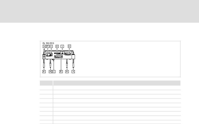
3.3.2EL 1xx ECO (PLC)
EL100e−001
Pos. Description
0HMI
1Screw clamp fixings
2PE connection
3SD/SDHC card slot
4CAN interface
5Ethernet port
6USB−A port
7Connection supply
8SD/SDHC card protection (eject protection)
LDCDS−EL100 EN 9.0
l |
17 |

4 |
Technical data |
|
General data and operating conditions |
|
|
4 |
Technical data |
4.1General data and operating conditions
Conformity and approval
Conformity
|
|
CE |
EN 61000−6−1 (−3), |
|
2002 residential area |
||||
|
|
|
|
|
VDE 0839−6−1 (−3) |
|
|
|
|
|
|
|
|
|
|
|
|
|
|
|
|
|
|
|
EN 61000−6−2 (−4), |
|
2006 industrial premises |
||
|
|
|
|
|
VDE 0839−6−2 (−4) |
|
|
|
|
|
|
|
|
|
|
|
|
|
|
|
|
|
|
|
EN 55022 |
|
|
|
|
|
|
|
|
|
|
|
|
|
|
|
|
|
|
|
EN 55024 |
|
Equipment of information technology |
||
|
|
|
|
|
|
|
|
|
|
Approbation |
|
|
|
|
|
||||
|
|
|
|
|
|
|
|
|
|
|
|
UL |
UL 508 |
|
Programmable Controllers (File−No. E236341) |
||||
|
|
|
|
|
CSA C22.2 |
|
|
|
|
|
|
|
|
|
|
|
|
|
|
Other |
|
|
|
|
|
||||
|
|
|
|
|
|
|
|
|
|
|
|
RoHS |
− |
|
Products lead−free in accordance with CE Directive |
||||
|
|
|
|
|
|
|
|
2011/65/EU |
|
|
|
|
|
|
|
|
|
||
Protection of persons and equipment |
|
|
|
||||||
Safety |
VDE0805 (EN60950), |
|
|
|
|||||
|
|
|
|
|
VDE0870, UL |
|
|
|
|
|
|
|
|
|
|
|
|
||
Type of protection |
|
|
|
IP65 (front) / IP20 (back) |
|||||
|
|
|
|
|
|
|
|
Type 1, 2 and 5 enclosure |
|
|
|
|
|
|
|
|
|
|
|
Class of protection |
|
|
3 |
|
|||||
|
|
|
|
|
|
|
|
|
|
Ambient conditions |
|
|
|
|
|
||||
Climatic |
|
|
|
|
|
||||
|
|
|
|
|
|
|
|
|
|
|
|
Temperature |
|
|
|
|
|
||
|
|
|
|
|
|
|
|
|
|
|
|
|
Storage/Transport |
|
|
|
0 ... +60 °C |
||
|
|
|
|
|
|
|
|
|
|
|
|
|
Operation |
|
|
|
|
|
|
|
|
|
|
|
|
|
|
|
|
|
|
|
|
EL 1xx ECO |
|
|
|
0 ... +50 °C |
|
|
|
|
|
EL 1xx CAN/MPI |
|
|
|
|
|
|
|
|
|
EL 1xx ECO PLC |
|
|
|
5 ... +45 °C |
|
|
|
|
|
EL 1xx PLC |
|
|
|
|
|
|
|
|
|
|
|
|
|||
|
|
Relative humidity |
|
|
|
10 ... 90 %, no condensation |
|||
|
|
|
|
|
|
|
|
||
|
|
Site altitude |
|
|
|
|
|
||
|
|
|
|
|
|
|
|
||
|
|
|
Storage/Transport |
|
|
|
< 12.000 m amsl |
||
|
|
|
|
|
|
|
|
||
|
|
|
Operation |
|
|
|
< 3.000 m amsl |
||
|
|
|
|
|
|
||||
Vibration test according to EN 61131−2 (programmable controllers) |
|||||||||
|
|
|
|
|
|
|
|||
|
|
Vibration |
|
EN 60068−2−6 |
|
1 g |
|||
|
|
|
|
|
|
|
|||
|
|
Shock |
|
EN 60068−2−27 |
|
15 g |
|||
|
|
|
|
|
|
||||
Mounting conditions |
|
|
|
|
|
||||
Mounting place |
|
|
|
Control cabinet door |
|||||
|
|
|
|
|
|||||
Mounting position |
|
|
|
Terminals at the bottom |
|||||
18 |
l |
LDCDS−EL100 EN 9.0

Technical data |
4 |
Electrical data
EL 1xx CAN/PLC/MPI
4.2Electrical data
4.2.1EL 1xx CAN/PLC/MPI
Supply |
|
|
|
Type EL xxx |
|
|
|
||
|
|
105m |
105 |
106 |
|
108 |
110 |
110s |
|
|
|
|
|
||||||
Voltage |
[V] |
|
|
DC 24 (+18 ... 30) |
|
|
|
||
|
|
|
|
|
|
|
|
|
|
Current at 24 V |
[A] |
0.25 |
0.3 |
0.3 |
|
0.5 |
|
0.5 |
|
|
|
|
|
|
|
|
|
|
|
Power at 24 V |
[W] |
6.0 |
7.2 |
7.2 |
|
12.0 |
|
12.0 |
|
|
|
|
|
|
|
|
|||
Buffer for real−time clock |
|
|
Typ EL xxx |
|
|
|
|||
dated |
|
105m |
105 |
106 |
|
108 |
110 |
110s |
|
|
|
|
|||||||
|
|
|
|
||||||
Battery |
|
|
|
|
|
|
|
|
|
Service life |
[year] |
|
|
7 (at 25 °C) |
|
|
|
||
|
|
|
|
|
|
|
|||
CPU and operating system |
|
|
Typ EL xxx |
|
|
|
|||
|
|
|
|
|
|
|
|
|
|
|
|
105m |
105 |
106 |
|
108 |
110 |
110s |
|
CPU type |
|
|
|
Intelâ Xscale PXA 270 |
|
|
|
||
|
|
|
|
|
|
|
|
||
Operating |
|
|
|
Windowsâ CE 5.0 |
|
|
|
||
system |
|
|
|
|
|
|
|
|
|
|
|
|
|
|
|
|
|
||
Memory |
|
|
|
Typ EL xxx CAN/MPI |
|
|
|
||
|
|
|
|
|
|
|
|
|
|
|
|
105m |
105 |
106 |
|
108 |
110 |
110s |
|
RAM |
[MB] |
|
|
|
64 |
|
|
|
|
|
|
|
|
|
|
|
|
|
|
Flash |
[MB] |
|
|
|
32 |
|
|
|
|
|
|
|
|
|
|
|
|
||
Exchangeable |
|
|
|
SD/SDHC card slot 1) |
|
|
|
||
disk storage |
|
|
|
|
|
|
|
|
|
|
|
|
|
|
|
|
|
||
Memory |
|
|
|
Typ EL xxx PLC |
|
|
|
||
|
|
|
|
|
|
|
|
|
|
|
|
105m |
105 |
106 |
|
108 |
110 |
110s |
|
RAM |
[MB] |
|
|
|
128 |
|
|
|
|
|
|
|
|
|
|
|
|
|
|
Flash |
[MB] |
|
|
|
64 |
|
|
|
|
|
|
|
|
|
|
|
|
||
Exchangeable |
|
|
|
SD/SDHC card slot 1) |
|
|
|
||
disk storage |
|
|
|
|
|
|
|
|
|
1)Due to the great variety of SD/SDHC cards available on the market, compatibility cannot be ensured. We do not know about any restrictions.
LDCDS−EL100 EN 9.0
l |
19 |

4 |
Technical data |
|
|
|
|
|
|
|
|
||
|
Electrical data |
|
|
|
|
|
|
|
|
|
|
|
EL 1xx CAN/PLC/MPI |
|
|
|
|
|
|
|
|
||
|
|
|
|
|
|
|
|
|
|
|
|
|
|
Screen |
|
|
|
|
Typ EL xxx |
|
|
||
|
|
|
|
105m |
105 |
|
|
106 |
|
||
|
|
|
|
|
|
|
|||||
|
|
Type |
|
|
|
Touch screen, resistive |
|
|
|||
|
|
|
|
|
|
|
|
|
|
|
|
|
|
Colours |
|
16 grey tones |
|
|
64 K |
|
64 K |
||
|
|
|
|
|
|
|
|
|
|
|
|
|
|
Display diagonal |
[cm] |
|
14.5 (5.7") |
|
|
16.3 (6.4") |
|
||
|
|
|
|
|
|
|
|
|
|
|
|
|
|
Visible size |
[mm] |
|
115 x 86 |
|
131 x 98 |
||||
|
|
|
|
|
|
|
|
|
|
|
|
|
|
Resolution |
[pixels] |
|
320 x 240 |
|
640 x 480 |
||||
|
|
|
|
|
|
|
|
|
|
|
|
|
|
Pixel size |
[mm] |
|
0.33 x 0.33 |
|
0.07 x 0.07 |
||||
|
|
|
|
|
|
|
|
|
|
|
|
|
|
Contrast |
|
− |
|
|
400:1 |
|
|
400:1 |
|
|
|
|
|
|
|
|
|
|
|
|
|
|
|
Brightness |
[cd/m2] |
180 |
|
|
250 |
|
|
250 |
|
|
|
Angle of view |
|
|
|
|
|
|
|
|
|
|
|
right |
[°] |
− |
|
|
60 |
|
|
65 |
|
|
|
left |
|
− |
|
|
60 |
|
|
65 |
|
|
|
top |
|
− |
|
|
40 |
|
|
50 |
|
|
|
bottom |
|
− |
|
|
50 |
|
|
60 |
|
|
|
|
|
|
|
|
|
|
|
|
|
|
|
Illumination |
|
|
Cathode−ray tube, adjustable |
|
|
||||
|
|
|
|
|
|
|
|
|
|
|
|
|
|
Service life at |
[h] |
40000 |
|
|
45000 |
|
|
50000 |
|
|
|
25°C |
|
|
|
|
|
|
|
|
|
|
|
|
|
|
|
|
|
|
|
|
|
|
|
Screen (continued) |
|
|
|
|
Typ EL xxx |
|
|
||
|
|
|
|
108 |
110 |
|
|
110s |
|
||
|
|
|
|
|
|
|
|||||
|
|
Type |
|
|
|
Touch screen, resistive |
|
|
|||
|
|
|
|
|
|
|
|
|
|
|
|
|
|
Colours |
|
|
|
|
64 K |
|
|
||
|
|
|
|
|
|
|
|
|
|
||
|
|
Display diagonal |
[cm] |
20.3 (8") |
|
26.4 (10.4") |
|
|
|||
|
|
|
|
|
|
|
|
|
|
|
|
|
|
Visible size |
[mm] |
162 x 122 |
|
|
216 x 163 |
|
|
||
|
|
|
|
|
|
|
|
|
|
|
|
|
|
Resolution |
[pixels] |
640 x 480 |
|
|
640 x 480 |
|
600 x 800 |
||
|
|
|
|
|
|
|
|
|
|
|
|
|
|
Pixel size |
[mm] |
0.25 x 0.25 |
|
|
0.33 x 0.33 |
|
|
||
|
|
|
|
|
|
|
|
|
|||
|
|
Contrast |
|
250:1 |
|
300:1 |
|
|
|||
|
|
|
|
|
|
|
|
|
|
|
|
|
|
Brightness |
[cd/m2] |
|
400 |
|
|
|
|
||
|
|
Angle of view |
|
|
|
|
|
|
|
|
|
|
|
right |
[°] |
65 |
|
60 |
|
|
|
||
|
|
left |
|
65 |
|
60 |
|
|
|
||
|
|
top |
|
55 |
|
40 |
|
|
|
||
|
|
bottom |
|
65 |
|
50 |
|
|
|
||
|
|
|
|
|
|
|
|
|
|||
|
|
Illumination |
|
|
Cathode−ray tube, adjustable |
|
|
||||
|
|
|
|
|
|
|
|
|
|
||
|
|
Service life at |
[h] |
|
50000 |
|
|
|
|
||
|
|
25°C |
|
|
|
|
|
|
|
|
|
20 |
l |
LDCDS−EL100 EN 9.0
|
|
|
|
|
|
Technical data |
4 |
|
||
|
|
|
|
|
|
|
Electrical data |
|
|
|
|
|
|
|
|
EL 1xx CAN/PLC/MPI |
|
|
|||
|
|
|
|
|
|
|
|
|
|
|
|
PLC functions |
|
|
|
Typ EL xxx PLC |
|
|
|
||
|
(EN 61131−3) |
|
105m |
105 |
106 |
|
108 |
110 |
110s |
|
|
|
|
|
|
||||||
|
Editor |
|
|
|
AWL, FUP, KOP, ST, AS, CFC |
|
|
|
||
|
|
|
|
|
|
|
|
|
|
|
|
Program code |
[kB] |
|
|
2048 |
|
|
|
|
|
|
|
|
|
|
|
|
|
|
|
|
|
Data memory |
|
|
|
|
|
|
|
|
|
|
Variables |
[kB] |
|
|
1024 |
|
|
|
|
|
|
Global Var. |
[kB] |
|
|
512 |
|
|
|
|
|
|
|
|
|
|
|
|
|
|
|
|
|
Memory location |
[kB] |
|
|
4 |
|
|
|
|
|
|
|
|
|
|
|
|
|
|
|
|
|
Process image |
|
|
|
|
|
|
|
|
|
|
Input |
[kB] |
|
|
4 |
|
|
|
|
|
|
Output |
[kB] |
|
|
4 |
|
|
|
|
|
|
|
|
|
|
|
|
|
|
|
|
|
Retain data |
[kB] |
|
|
128 |
|
|
|
|
|
|
|
|
|
|
|
|
|
|||
|
UPS |
|
|
Integrated to save retain data to the flash memory |
|
|
||||
|
|
|
|
|
|
|
|
|
|
|
|
Target |
|
|
|
|
|
|
|
|
|
|
L−force Logic |
|
|
|
V1.x |
|
|
|
|
|
|
EL1xx |
|
|
|
|
|
|
|
|
|
|
|
|
|
|
|
|
|
|
|
|
|
Task runtime |
[ms] |
|
|
³10 |
|
|
|
|
|
|
|
|
|
|
|
|
|
|
|
|
|
Ports |
|
|
|
|
|
|
|
|
|
|
COM 1 |
Type |
|
RS232 |
|
|
|
|
||
|
|
|
|
|
|
|
|
|||
|
|
Connection |
|
SUB−D, 9−pole, connector |
|
|
|
|||
|
|
|
|
|
|
|
|
|
||
|
LAN |
Type |
|
Ethernet |
|
|
|
|
||
|
|
|
|
|
|
|
|
|
||
|
|
Protocol |
|
TCP/IP |
|
|
|
|
||
|
|
|
|
|
|
|
|
|
||
|
|
Baud rate |
|
10/100 Mbits |
|
|
|
|
||
|
|
|
|
|
|
|
|
|
||
|
|
Connection |
|
RJ45, socket |
|
|
|
|
||
|
|
|
|
|
|
|
|
|||
|
USB |
Type |
|
2.0 (1.1−compatible) |
|
|
|
|||
|
|
|
|
|
|
|
|
|||
|
|
Connection |
|
Type A and type B, socket |
|
|
|
|||
|
|
|
|
|
|
|
|
|
||
|
CAN 1) |
Type |
|
CAN, ISO11898 |
|
|
|
|
||
|
|
Protocol |
|
Lenze system bus CAN |
|
|
|
|||
|
|
|
|
|
|
|
||||
|
|
Topology |
|
Line, terminated on both sides with 120 W |
|
|
||||
|
|
|
|
|
|
|
|
|
||
|
|
Node |
|
Master or slave |
|
|
|
|
||
|
|
|
|
|
|
|
|
|
||
|
|
Number of nodes |
|
Max. 63 |
|
|
|
|
||
|
|
|
|
|
|
|
|
|||
|
|
Baud rate |
|
See CAN communication manual |
|
|
|
|||
|
|
|
|
|
|
|
|
|||
|
|
Bus length |
|
See CAN communication manual |
|
|
|
|||
|
|
|
|
|
|
|
|
|||
|
|
Connection |
|
SUB−D, 9−pole, connector |
|
|
|
|||
|
|
|
|
|
|
|
|
|
||
|
MPI 1) |
Type |
|
RS485 |
|
|
|
|
||
|
|
Protocol |
|
MPI |
|
|
|
|
||
|
|
|
|
|
|
|
||||
|
|
Topology |
|
Line, terminated on both sides with 200 W |
|
|
||||
|
|
|
|
|
|
|
|
|
||
|
|
Node |
|
Master |
|
|
|
|
||
|
|
|
|
|
|
|
|
|||
|
|
Number of nodes |
|
Max. 32 per segment |
|
|
|
|||
|
|
|
|
|
Max. 127 with RS485 repeaters |
|
|
|
||
|
|
|
|
|
|
|
|
|||
|
|
Baud rate |
|
19.2 kBaud ... 12 MBaud |
|
|
|
|||
|
|
|
|
|
|
|
|
|
||
|
|
Bus length |
|
Max. 50 m |
|
|
|
|
||
|
|
|
|
|
|
|
|
|||
|
|
Connection |
|
SUB−D, 9−pole, connector |
|
|
|
|||
1* optionally CAN or MPI
LDCDS−EL100 EN 9.0
l |
21 |

4 Technical data
Electrical data EL 1xx ECO (PLC)
4.2.2EL 1xx ECO (PLC)
Supply |
|
Type EL xxx ECO |
|
|
|
103 |
|
Voltage |
[V] |
DC 24 (+18 ... 30) |
|
|
|
|
|
Current at 24 V |
[A] |
0.21 |
|
|
|
|
|
Power at 24 V |
[W] |
5.0 |
|
|
|
|
|
Buffer for real−time clock |
Typ EL xxx ECO |
|
|
dated |
|
103 |
|
|
|
|
|
Capacitor |
[week] |
|
|
Max. buffer time |
|
2 |
|
|
|
|
|
CPU and operating system |
Typ EL xxx ECO |
|
|
|
|
103 |
|
CPU type |
|
IntelR Xscale PXA 270 |
|
|
|
|
|
Operating |
|
WindowsR CE 5.0 |
|
system |
|
|
|
|
|
|
|
Memory |
|
Typ EL xxx ECO CAN |
|
|
|
103 |
|
RAM |
[MB] |
64 |
|
|
|
|
|
Flash |
[MB] |
32 |
|
|
|
|
|
Exchangeable |
|
SD/SDHC card slot 1) |
|
disk storage |
|
|
|
|
|
|
|
Memory |
|
Typ EL xxx ECO PLC |
|
|
|
|
|
|
|
103 |
|
RAM |
[MB] |
64 |
|
|
|
|
|
Flash |
[MB] |
32 |
|
|
|
|
|
Exchangeable |
|
SD/SDHC card slot 1) |
|
disk storage |
|
|
|
1)Due to the great variety of SD/SDHC cards available on the market, compatibility cannot be ensured. We do not know about any restrictions.
22 |
l |
LDCDS−EL100 EN 9.0

Technical data |
4 |
Electrical data
EL 1xx ECO (PLC)
Screen |
|
|
|
Typ EL xxx ECO |
|
|
|
|
103 |
|
|
Type |
|
|
|
Touch screen, resistive |
|
|
|
|
|
|
|
Colours |
|
|
|
64 K |
|
|
|
|
|
|
|
Display diagonal |
[cm] |
|
8.9 (3.5") |
|
|
|
|
|
|
|
|
Visible size |
[mm] |
|
|
70 x 53 |
|
|
|
|
|
|
|
Resolution |
[pixels] |
|
|
320 x 240 |
|
|
|
|
|
|
|
Pixel size |
[mm] |
|
|
0.7 x 0.22 |
|
|
|
|
|
|
|
Contrast |
|
|
400:1 |
|
|
|
|
|
|
|
|
Brightness |
[cd/m2] |
|
300 |
|
|
Angle of view |
|
|
|
|
|
right |
[°] |
|
65 |
|
|
left |
|
|
65 |
|
|
top |
|
|
50 |
|
|
bottom |
|
|
60 |
|
|
|
|
|
|
|
|
Illumination |
|
|
|
LED |
|
|
|
|
|
|
|
Service life at |
[h] |
|
|
− |
|
25°C |
|
|
|
|
|
|
|
|
|
|
|
PLC functions |
|
|
|
Typ EL xxx ECO PLC |
|
(EN 61131−3) |
|
|
103 |
|
|
|
|
|
|
||
Editor |
|
|
|
AWL, FUP, KOP, ST, AS, CFC |
|
|
|
|
|
|
|
Program code |
[kB] |
|
256 |
|
|
|
|
|
|
|
|
Data memory |
|
|
|
|
|
Variables |
[kB] |
|
64 |
|
|
Global Var. |
[kB] |
|
64 |
|
|
|
|
|
|
|
|
Memory location |
[kB] |
|
4 |
|
|
|
|
|
|
|
|
Process image |
|
|
|
|
|
Input |
[kB] |
|
1 |
|
|
Output |
[kB] |
|
1 |
|
|
|
|
|
|
|
|
Retain data |
[kB] |
|
16 |
|
|
|
|
|
|
|
|
UPS |
|
|
Integrated to save retain data to the flash memory |
|
|
|
|
|
|
|
|
Target |
|
|
|
|
|
L−force Logic |
|
|
|
V2.x |
|
EL1xx |
|
|
|
|
|
Task runtime |
[ms] |
|
³100 |
|
|
|
|
|
|
|
|
Ports |
|
|
|
|
|
LAN |
Type |
|
Ethernet |
|
|
|
|
|
|
|
|
|
Protocol |
|
TCP/IP |
|
|
|
|
|
|
|
|
|
Baud rate |
|
10/100 Mbits |
|
|
|
|
|
|
|
|
|
Connection |
|
RJ45, socket |
|
|
|
|
|
|
|
|
USB |
Type |
|
2.0 (1.1−compatible) |
|
|
|
|
|
|
|
|
|
Connection |
|
Type A, socket |
|
|
|
|
|
|
|
|
CAN |
Type |
|
CAN, ISO11898 |
|
|
|
|
|
|
|
|
|
Protocol |
|
Lenze system bus CAN |
|
|
|
|
|
|
|
|
|
Topology |
|
Line, terminated on both sides with 120 W |
|
|
|
|
|
|
|
|
|
Node |
|
Master or slave |
|
|
|
|
|
|
|
|
|
Number of nodes |
|
Max. 63 |
|
|
|
|
|
|
|
|
|
Baud rate |
|
See CAN communication manual |
|
|
|
|
|
|
|
|
|
Bus length |
|
See CAN communication manual |
|
|
|
|
|
|
|
|
|
Connection |
|
SUB−D, 9−pole, connector |
|
|
LDCDS−EL100 EN 9.0
l |
23 |
4 Technical data
Mechanical data
EL 1xx CAN/PLC/MPI
4.3Mechanical data
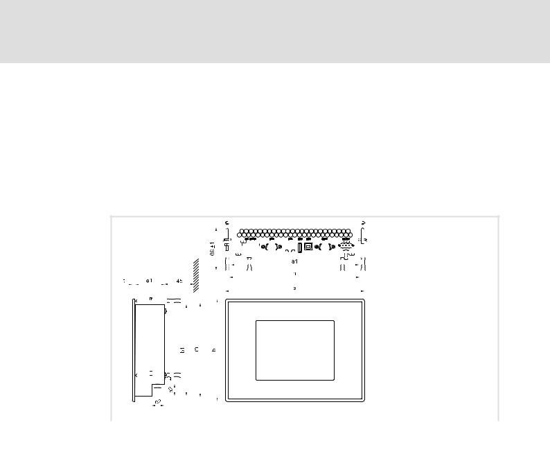
4.3.1EL 1xx CAN/PLC/MPI
Design and weight |
|
|
|
|
|
|
|
|
|
|
|
|
|
|
|
|
|
|
|
|
|
|
|
|
|
|
|
|
|
|
|
|
|
|
|
|
|
|
|
|
|
|
|
|
|
|
|
|
|
|
Type EL xxx |
|
|
|
|
|||||||||||||||||||||||||||||||||
|
|
|
|
|
|
|
|
|
|
|
|
|
|
|
|
|
|
|
|
|
|
|
|
|
|
|
|
|
|
|
|
|
|
|
105m |
105 |
|
|
|
|
|
|
|
|
|
|
106 |
|
|
|
|
|
|
|
|
|
|
|
108 |
110 |
110s |
|
||||||||||||||||||||||||||
|
|
|
|
|
|
|
|
|
|
|
|
|
|
|
|
|
|
|
|
|
|
|
|
|
|
|
|
|
|
|
|
|
|
|
|
|
|
|
|
|
|
|
|
|
|
|
|
|
|
|
|
|
|
|
|
|
||||||||||||||||||||||||||||||||
Front |
|
|
|
|
|
|
|
|
|
|
|
|
|
|
|
|
|
|
|
|
|
|
|
|
|
|
Aluminium with polyester film to DIN 42115 |
|
|
|||||||||||||||||||||||||||||||||||||||||||||||||||||||||||
|
|
|
|
|
|
|
|
|
|
|
|
|
|
|
|
|
|
|
|
|
|
|
|
|
|
|
|
|
|
|
|
|
|
|
|
|
|
|
|
|
|
|
|
|
|
|
|
|
|
|
|
|
|
|
|
|
|
|
|
|
|
|
|
|
|
|
|
|
|
|
|
|
|
|
|
|
|
|
|
|
|
|
|
|
|
|
|
|
Cover |
|
|
|
|
|
|
|
|
|
|
|
|
|
|
|
|
|
|
|
|
|
|
|
|
|
|
|
|
|
|
|
|
|
|
|
|
|
|
|
|
|
|
|
|
Sheet steel, galvanised |
|
|
|
||||||||||||||||||||||||||||||||||||||||
|
|
|
|
|
|
|
|
|
|
|
|
|
|
|
|
|
|
|
|
|
|
|
|
|
|
|
|
|
|
|
|
|
|
|
|
|
|
|
|
|
|
|
|
|
|
|
|
|
|
|
|
|
|
|
|
|
|
|
|
|
|
|
|
|
|
|
|
|
|
|
|
|
|
|
|
|
|
|
|
|
|
|
|
|
|
|
|
|
Weight |
|
|
[kg] |
1.1 |
|
|
|
|
1.1 |
|
|
|
|
|
|
|
|
|
|
1.2 |
|
|
|
|
|
|
|
|
|
|
|
1.5 |
|
2.0 |
|
|||||||||||||||||||||||||||||||||||||||||||||||||||||
|
|
|
|
|
|
|
|
|
|
|
|
|
|
|
|
|
|
|
|
|
|
|
|
|
|
|
|
|
|
|
|
|
|
|
|
|
|
|
|
|
|
|
|
|
|
|
|
|
|
|
|
|
|
|
|
|
|
|
|
|
|
|
|
|
|
|
|
|
|
|
|
|
|
|
|
|
|
|
|
|
|
|
|
|
|
|
|
|
|
|
|
|
|
|
|
|
|
|
|
|
|
|
|
|
|
|
|
|
|
|
|
|
|
|
|
|
|
|
|
|
|
|
|
|
|
|
|
|
|
|
|
|
|
|
|
|
|
|
|
|
|
|
|
|
|
|
|
|
|
|
|
|
|
|
|
|
|
|
|
|
|
|
|
|
|
|
|
|
|
|
|
|
|
|
|
|
|
|
|
|
|
|
|
|
|
|
|
|
|
|
|
|
|
|
|
|
|
|
|
|
|
|
|
|
|
|
|
|
|
|
|
|
|
|
|
|
|
|
|
|
|
|
|
|
|
|
|
|
|
|
|
|
|
|
|
|
|
|
|
|
|
|
|
|
|
|
|
|
|
|
|
|
|
|
|
|
|
|
|
|
|
|
|
|
|
|
|
|
|
|
|
|
|
|
|
|
|
|
|
|
|
|
|
|
|
|
|
|
|
|
|
|
|
|
|
|
|
|
|
|
|
|
|
|
|
|
|
|
|
|
|
|
|
|
|
|
|
|
|
|
|
|
|
|
|
|
|
|
|
|
|
|
|
|
|
|
|
|
|
|
|
|
|
|
|
|
|
|
|
|
|
|
|
|
|
|
|
|
|
|
|
|
|
|
|
|
|
|
|
|
|
|
|
|
|
|
|
|
|
|
|
|
|
|
|
|
|
|
|
|
|
|
|
|
|
|
|
|
|
|
|
|
|
|
|
|
|
|
|
|
|
|
|
|
|
|
|
|
|
|
|
|
|
|
|
|
|
|
|
|
|
|
|
|
|
|
|
|
|
|
|
|
|
|
|
|
|
|
|
|
|
|
|
|
|
|
|
|
|
|
|
|
|
|
|
|
|
|
|
|
|
|
|
|
|
|
|
|
|
|
|
|
|
|
|
|
|
|
|
|
|
|
|
|
|
|
|
|
|
|
|
|
|
|
|
|
|
|
|
|
|
|
|
|
|
|
|
|
|
|
|
|
|
|
|
|
|
|
|
|
|
|
|
|
|
|
|
|
|
|
|
|
|
|
|
|
|
|
|
|
|
|
|
|
|
|
|
|
|
|
|
|
|
|
|
|
|
|
|
|
|
|
|
|
|
|
|
|
|
|
|
|
|
|
|
|
|
|
|
|
|
|
|
|
|
|
|
|
|
|
|
|
|
|
|
|
|
|
|
|
|
|
|
|
|
|
|
|
|
|
|
|
|
|
|
|
|
|
|
|
|
|
|
|
|
|
|
|
|
|
|
|
|
|
|
|
|
|
|
|
|
|
|
|
|
|
|
|
|
|
|
|
|
|
|
|
|
|
|
|
|
|
|
|
|
|
|
|
|
|
|
|
|
|
|
|
|
|
|
|
|
|
|
|
|
|
|
|
|
|
|
|
|
|
|
|
|
|
|
|
|
|
|
|
|
|
|
|
|
|
|
|
|
|
|
|
|
|
|
|
|
|
|
|
|
|
|
|
|
|
|
|
|
|
|
|
|
|
|
|
|
|
|
|
|
|
|
|
|
|
|
|
|
|
|
|
|
|
|
|
|
|
|
|
|
|
|
|
|
|
|
|
|
|
|
|
|
|
|
|
|
|
|
|
|
|
|
|
|
|
|
|
|
|
|
|
|
|
|
|
|
|
|
|
|
|
|
|
|
|
|
|
|
|
|
|
|
|
|
|
|
|
|
|
|
|
|
|
|
|
|
|
|
|
|
|
|
|
|
|
|
|
|
|
|
|
|
|
|
|
|
|
|
|
|
|
|
|
|
|
|
|
|
|
|
|
|
|
|
|
|
|
|
|
|
|
|
|
|
|
|
|
|
|
|
|
|
|
|
|
|
|
|
|
|
|
|
|
|
|
|
|
|
|
|
|
|
|
|
|
|
|
|
|
|
|
|
|
|
|
|
|
|
|
|
|
|
|
|
|
|
|
|
|
|
|
|
|
|
|
|
|
|
|
|
|
|
|
|
|
|
|
|
|
|
|
|
|
|
|
|
|
|
|
|
|
|
|
|
|
|
|
|
|
|
|
|
|
|
|
|
|
|
|
|
|
|
|
|
|
|
|
|
|
|
|
|
|
|
|
|
|
|
|
|
|
|
|
|
|
|
|
|
|
|
|
|
|
|
|
|
|
|
|
|
|
|
|
|
|
|
|
|
|
|
|
|
|
|
|
|
|
|
|
|
|
|
|
|
|
|
|
|
|
|
|
|
|
|
|
|
|
|
|
|
|
|
|
|
|
|
|
|
|
|
|
|
|
|
|
|
|
|
|
|
|
|
|
|
|
|
|
|
|
|
|
|
|
|
|
|
|
|
|
|
|
|
|
|
|
|
|
|
|
|
|
|
|
|
|
|
|
|
|
|
|
|
|
|
|
|
|
|
|
|
|
|
|
|
|
|
|
|
|
|
|
|
|
|
|
|
|
|
|
|
|
|
|
|
|
|
|
|
|
|
|
|
|
|
|
|
|
|
|
|
|
|
|
|
|
|
|
|
|
|
|
|
|
|
|
|
|
|
|
|
|
|
|
|
|
|
|
|
|
|
|
|
|
|
|
|
|
|
|
|
|
|
|
|
|
|
|
|
|
|
|
|
|
|
|
|
|
|
|
|
|
|
|
|
|
|
|
|
|
|
|
|
|
|
|
|
|
|
|
|
|
|
|
|
|
|
|
|
|
|
|
|
|
|
|
|
|
|
|
|
|
|
|
|
|
|
|
|
|
|
|
|
|
|
|
|
|
|
|
|
|
|
|
|
|
|
|
|
|
|
|
|
|
|
|
|
|
|
|
|
|
|
|
|
|
|
|
|
|
|
|
|
|
|
|
|
|
|
|
|
|
|
|
|
|
|
|
|
|
|
|
|
|
|
|
|
|
|
|
|
|
|
|
|
|
|
|
|
|
|
|
|
|
|
|
|
|
|
|
|
|
|
|
|
|
|
|
|
|
|
|
|
|
|
|
|
|
|
|
|
|
|
|
|
|
|
|
|
|
|
|
|
|
|
|
|
|
|
|
|
|
|
|
|
|
|
|
|
|
|
|
|
|
|
|
|
|
|
|
|
|
|
|
|
|
|
|
|
|
|
|
|
|
|
|
|
|
|
|
|
|
|
|
|
|
|
|
|
|
|
|
|
|
|
|
|
|
|
|
|
|
|
|
|
|
|
|
|
|
|
|
|
|
|
|
|
|
|
|
|
|
|
|
|
|
|
|
|
|
|
|
|
|
|
|
|
|
|
EL100−002 |
|
|
|
|
|
|
|
|
|
|
|
|
|
|
Type |
|
|
|
Dimensions |
|
|
|
Mounting cutout |
||||
|
|
|
|
[mm] |
|
|
|
|
[mm] |
|||
|
a |
a1 |
b |
b1 |
b2 |
e1 |
e2 |
t |
n ±0.5 |
|
m ±0.5 |
|
|
|
|
|
|
|
|
|
|
|
|
|
|
EL 105 |
|
|
|
|
|
|
|
|
|
|
|
|
|
|
|
|
|
|
|
|
|
|
|
|
|
EL 105M |
210 |
193 |
155 |
138 |
17.5 |
43.6 |
17.6 |
4 |
197 |
|
142 |
|
EL 106 |
|
|
|
|
|
|
|
|
|
|
|
|
|
|
|
|
|
|
|
|
|
|
|
|
|
EL 108 |
250 |
220 |
180 |
156.5 |
33.7 |
46 |
18 |
4 |
224 |
|
160.5 |
|
|
|
|
|
|
|
|
|
|
|
|
|
|
EL 110 |
275 |
257 |
220 |
201 |
75.5 |
46 |
18 |
4 |
261 |
|
205 |
|
|
|
|
||||||||||
EL 110s |
|
|
||||||||||
|
|
|
|
|
|
|
|
|
|
|
|
|
24 |
l |
LDCDS−EL100 EN 9.0
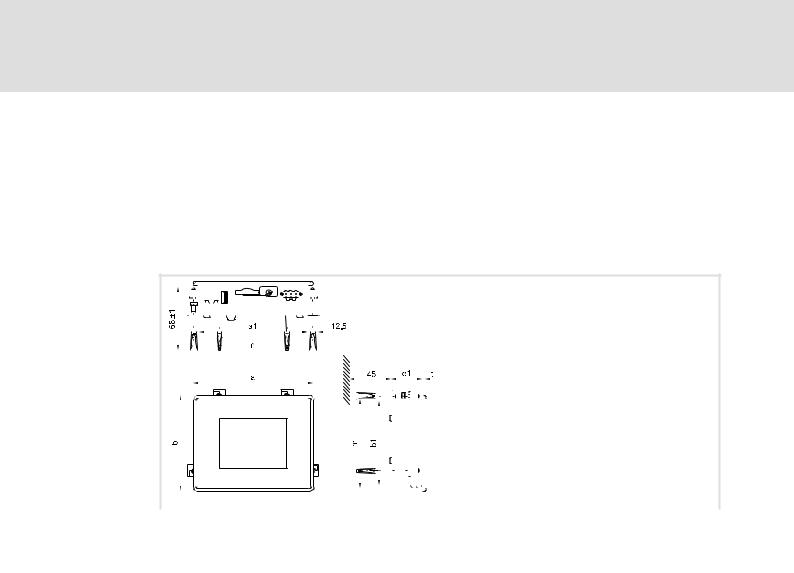
Technical data |
4 |
Mechanical data
EL 1xx ECO (PLC)
4.3.2EL 1xx ECO (PLC)
Design and weight |
|
|
|
|
|
|
|
|
|
|
|
|
|
|
|
|
|
|
|
|
|
|
|
|
|
|
|
|
|
|
|
|
|
|
|
|
|
Type EL xxx ECO |
|
|||||||||||
|
|
|
|
|
|
|
|
|
|
|
|
|
|
|
|
|
|
|
|
|
|
|
|
|
|
|
|
|
|
|
|
|
|
|
|
|
|
|
|
|
|
|
|
|
|
|
|
|
|
|
|
|
|
|
|
|
|
|
|
|
|
|
|
|
|
|
|
|
|
|
|
103 |
|
||||||||||||||||||||||||||||
Front |
|
|
|
|
|
|
|
|
|
|
|
|
|
|
|
|
|
|
|
|
|
|
|
|
|
|
Aluminium with polyester film to DIN 42115 |
|
||||||||||||||||||||||
|
|
|
|
|
|
|
|
|
|
|
|
|
|
|
|
|
|
|
|
|
|
|
|
|
|
|
|
|
|
|
|
|
|
|
|
|
|
|
|
|
|
|
|
|
|
|
|
|
|
|
Cover |
|
|
|
|
|
|
|
|
|
|
|
|
|
|
|
|
|
|
|
|
|
|
|
|
|
|
|
|
|
|
|
|
|
|
|
|
|
Sheet steel, galvanised |
|
|||||||||||
|
|
|
|
|
|
|
|
|
|
|
|
|
|
|
|
|
|
|
|
|
|
|
|
|
|
|
|
|
|
|
|
|
|
|
|
|
|
|
|
|
|
|
|
|
|
|
|
|
|
|
Weight |
|
[kg] |
0.4 |
|
||||||||||||||||||||||||||||||||||||||||||||||
|
|
|
|
|
|
|
|
|
|
|
|
|
|
|
|
|
|
|
|
|
|
|
|
|
|
|
|
|
|
|
|
|
|
|
|
|
|
|
|
|
|
|
|
|
|
|
|
|
|
|
|
|
|
|
|
|
|
|
|
|
|
|
|
|
|
|
|
|
|
|
|
|
|
|
|
|
|
|
|
|
|
|
|
|
|
|
|
|
|
|
|
|
|
|
|
|
|
|
|
|
|
|
|
|
|
|
|
|
|
|
|
|
|
|
|
|
|
|
|
|
|
|
|
|
|
|
|
|
|
|
|
|
|
|
|
|
|
|
|
|
|
|
|
|
|
|
|
|
|
|
|
|
|
|
|
|
|
|
|
|
|
|
|
|
|
|
|
|
|
|
|
|
|
|
|
|
|
|
|
|
|
|
|
|
|
|
|
|
|
|
|
|
|
|
|
|
|
|
|
|
|
|
|
|
|
|
|
|
|
|
|
|
|
|
|
|
|
|
|
|
|
|
|
|
|
|
|
|
|
|
|
|
|
|
|
|
|
|
|
|
|
|
|
|
|
|
|
|
|
|
|
|
|
|
|
|
|
|
|
|
|
|
|
|
|
|
|
|
|
|
|
|
|
|
|
|
|
|
|
|
|
|
|
|
|
|
|
|
|
|
|
|
|
|
|
|
|
|
|
|
|
|
|
|
|
|
|
|
|
|
|
|
|
|
|
|
|
|
|
|
|
|
|
|
|
|
|
|
|
|
|
|
|
|
|
|
|
|
|
|
|
|
|
|
|
|
|
|
|
|
|
|
|
|
|
|
|
|
|
|
|
|
|
|
|
|
|
|
|
|
|
|
|
|
|
|
|
|
|
|
|
|
|
|
|
|
|
|
|
|
|
|
|
|
|
|
|
|
|
|
|
|
|
|
|
|
|
|
|
|
|
|
|
|
|
|
|
|
|
|
|
|
|
|
|
|
|
|
|
|
|
|
|
|
|
|
|
|
|
|
|
|
|
|
|
|
|
|
|
|
|
|
|
|
|
|
|
|
|
|
|
|
|
|
|
|
|
|
|
|
|
|
|
|
|
|
|
|
|
|
|
|
|
|
|
|
|
|
|
|
|
|
|
|
|
|
|
|
|
|
|
|
|
|
|
|
|
|
|
|
|
|
|
|
|
|
|
|
|
|
|
|
|
|
|
|
|
|
|
|
|
|
|
|
|
|
|
|
|
|
|
|
|
|
|
|
|
|
|
|
|
|
|
|
|
|
|
|
|
|
|
|
|
|
|
|
|
|
|
|
|
|
|
|
|
|
|
|
|
|
|
|
|
|
|
|
|
|
|
|
|
|
|
|
|
|
|
|
|
|
|
|
|
|
|
|
|
|
|
|
|
|
|
|
|
|
|
|
|
|
|
|
|
|
|
|
|
|
|
|
|
|
|
|
|
|
|
|
|
|
|
|
|
|
|
|
|
|
|
|
|
|
|
|
|
|
|
|
|
|
|
|
|
|
|
|
|
|
|
|
|
|
|
|
|
|
|
|
|
|
|
|
|
|
|
|
|
|
|
|
|
|
|
|
|
|
|
|
|
|
|
|
|
|
|
|
|
|
|
|
|
|
|
|
|
|
|
|
|
|
|
|
|
|
|
|
|
|
|
|
|
|
|
|
|
|
|
|
|
|
|
|
|
|
|
|
|
|
|
|
|
|
|
|
|
|
|
|
|
|
|
|
|
|
|
|
|
|
|
|
|
|
|
|
EL100e−002 |
|
|
|
|
|
|
|
|
|
|
|
||
Type |
|
|
Dimensions |
|
|
Mounting cutout |
|||||
|
|
|
|
[mm] |
|
|
|
[mm] |
|||
|
a |
a1 |
b |
|
b1 |
e1 |
t |
n ±0.5 |
|
m ±0.5 |
|
EL 103 |
130 |
116.5 |
104 |
|
90.5 |
33.6 |
3 |
120 |
|
94 |
|
ECO |
|
|
|
||||||||
|
|
|
|
|
|
|
|
|
|
|
|
LDCDS−EL100 EN 9.0
l |
25 |

5 |
Mechanical installation |
|
Important notes |
|
|
5 |
Mechanical installation |
5.1Important notes
The installation must be carried out by qualified, skilled personnel familiar with the applicable national standards.
(Stop!
Sensitive front frame gasket
During mounting, the gasket of the front frame is exposed and can be damaged.
Possible consequences:
ƒThe degree of protection provided by the enclosure mentioned in the technical data is not attained.
Protective measures:
ƒHandle the gasket with care during mounting.
ƒProtect the gasket against ultraviolet rays.
ƒEach time before you mount the device, check whether the gasket is intact.
(Stop!
Sensitive touchscreen surface
The touchscreen foil is very sensitive to external forces and can be damaged by improper handling.
Possible consequences:
ƒThe touchscreen foil becomes damaged, scratched or dull.
Protective measures:
ƒAvoid contact of the touchscreen foil with pointed or hard objects.
ƒAlways use a touch pen or your fingers to operate the touchscreen. Never use objects such as ballpoint pens, pencils, etc.
ƒWhen removing dirt and fingerprints, observe the notes given in the chapter "Cleaning" (¶ 90).
)Note!
When selecting the place where the PC is to be installed, pay attention to an ergonomic positioning of the screen and to the incidence of light which might cause reflections on the screen.
26 |
l |
LDCDS−EL100 EN 9.0
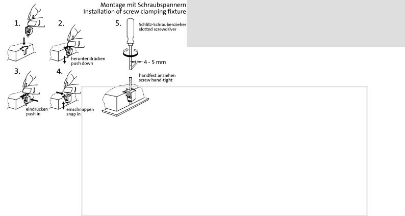
Mechanical installation |
5 |
Mounting steps
5.2Mounting steps
EL100−004
How to assemble the HMI:
1.Cut the mounting cutout out of the control cabinet door.
2.Assemble the upper screw clamping fixtures (see figure).
3.Check if the gasket under the front panel is located correctly.
4.Insert the device into the mounting cutout, secure it by hand against falling down and tighten the assembled screw clamping fixtures hand−tight.
5.Secure the device by hand, assemble the remaining screw clamping fixtures and tighten them hand−tight.
6.Check if the device is securely located in the mounting cutout and if the front panel gasket is located correctly.
–If necessary, loosen the screw clamping fixtures, re−align the device or gasket and tighten the screw clamping fixtures hand−tight.
–If the gasket is not located correctly, protection class IP65 is not reached on the front of the device!
LDCDS−EL100 EN 9.0
l |
27 |

6 |
Electrical installation |
|
Important notes |
|
|
6 |
Electrical installation |
6.1Important notes
The installation must be carried out by qualified, skilled personnel familiar with the applicable national standards.
(Stop!
Short circuit and static discharge
The device contains components which are endangered in the case of short circuit or static discharge.
Possible consequences:
ƒThe device or parts of it will be destroyed.
Protective measures:
ƒAlways switch off the voltage supply when working on the device. This particularly applies:
–Before connecting / disconnecting connectors.
–Before plugging in / plugging out modules.
ƒAll persons handling printed circuit boards have to take account of ESD measures.
ƒContacts of plug connectors must not be touched.
ƒPrinted circuit boards may be touched only at places free from electrical contacts and may be placed only on appropriate materials (e.g. on ESD packaging or conductive foam material).
ƒPrinted circuit boards may only be transported and stored in ESD packaging.
28 |
l |
LDCDS−EL100 EN 9.0

Electrical installation |
6 |
Wiring according to EMC
6.2Wiring according to EMC
General notes l The electromagnetic compatibility of the system depends on the type and accuracy of the installation. Please especially note the following:
–Structure
–Shielding
–Earthing
lIn the case of a differing installation it is required for evaluating the conformity to the EMC Directive to check the system with regard to compliance with the EMC limit values. This for instance applies to:
–The use of unshielded cables
lThe end user is responsible for compliance with the EMC Directive.
–If you observe the following measures, you can be sure that no EMC problems will occur during operation and that the EMC Directive or the EMC law is met.
–If devices which do not meet the CE requirement with regard to noise immunity
EN 61000−4−2 are actuated near the system, these devices can be affected electromagnetically by the system.
Structure |
l Connect device to the earthed mounting plate: |
|
– Mounting plates with an electroconductive surface (zinc−coated or stainless steel) allow for |
|
continuous contacting. |
|
– Coated plates are not suitable for an EMC−compliant installation. |
|
l If you use several mounting plates: |
|
– Connect mounting plates to each other on a large surface and in a conductive manner (e.g. |
|
by means of copper strips). |
|
l When installing the cables, observe a spatial separation of signal and mains cables. |
|
l Route the cables as near to the reference potential as possible. Freely suspended cables act |
|
like aerials. |
|
|
Shielding |
l Preferably only use cables with a braid. |
|
l The coverage of the shield should be more than 80%. |
|
l In the case of data lines for a serial coupling, always use metallic or metallised plugs. Connect |
|
the shield of the data line on the connector shell. |
|
|
Earthing |
l Earth all metallically conductive components by the use of corresponding cables from a |
|
central earthing point (PE rail). |
|
l Comply with the minimum cross−sections defined in the safety instructions: |
|
– With regard to EMC, however, not the cable cross−section, but the surface of the cable and |
|
of the extensive contacting is decisive. |
LDCDS−EL100 EN 9.0
l |
29 |
Loading...