


 Loading...
 Show/Hide Bookmarks
L
Manual
Global Drive
PLC Developer Studio
Global Drive
9300 Servo PLC
This documentation is valid for the following Lenze PLC devices:
|
Type designation |
As of hardware version |
As of software version |
9300 Servo PLC |
EVS93XX−xl |
7A |
8.0 |
|
|
|
|
9300 Servo PLC |
EVS93XX−xT |
7A |
8.0 |
What’s new?
Version |
|
Changes |
1.4 |
07/2000 |
Revised edition for the 9300 Servo PLC as of software version V1.0 |
|
|
|
2.0 |
07/2001 |
Revised edition for the 9300 Servo PLC as of software version V2.0 |
|
|
|
3.0 |
01/2003 |
Revised edition for the 9300 Servo PLC as of software version V6.0 |
4.0/4.1 |
08/2006 |
Revised edition for the 9300 Servo PLC as of software version V7.0 |
5.0 |
10/2010 |
Revised edition for the 9300 Servo PLC as of software version V8.0 |
|
|
|
5.1 |
09/2013 |
General corrections |
Important note:
The software is supplied to the user as described in this document. Any risks resulting from its quality or use remain the responsibility of the user. The user must provide all safety measures protecting against possible maloperation.
We do not take any liability for direct or indirect damage, e.g. profit loss, order loss or any loss regarding business.
ã 2013 Lenze Automation GmbH
No part of this documentation may be copied or made available to third parties without the explicit written approval of Lenze Automation GmbH.
All information given in this documentation has been carefully selected and tested for compliance with the hardware and software described. Nevertheless, discrepancies cannot be ruled out. We do not accept any responsibility or liability for any damage that may occur. Required correction will be included in updates of this documentation.
All product names mentioned in this documentation are trademarks of the corresponding owners.
Version 5.1 09/2013

9300 Servo PLC
Contents
1 Preface and general information . . . . . . . . . . . . . . . . . . . . . . . . . . . . . . . . . . . . . . . . . . . |
1−1 |
||
1.1 |
About this Manual . . . . . . . . . . . . . . . . . . . . . . . . . . . . . . . . . . . . . . . . . . . . . . . . . . . . . . . . . . . . . . . . . |
1−1 |
|
|
1.1.1 |
Conventions used in this Manual . . . . . . . . . . . . . . . . . . . . . . . . . . . . . . . . . . . . . . . . . . . . . . . |
1−1 |
|
1.1.2 |
System block descriptions . . . . . . . . . . . . . . . . . . . . . . . . . . . . . . . . . . . . . . . . . . . . . . . . . . . . |
1−1 |
|
1.1.3 |
Pictographs in this Manual . . . . . . . . . . . . . . . . . . . . . . . . . . . . . . . . . . . . . . . . . . . . . . . . . . . . |
1−2 |
|
1.1.4 |
Terminology used . . . . . . . . . . . . . . . . . . . . . . . . . . . . . . . . . . . . . . . . . . . . . . . . . . . . . . . . . . |
1−2 |
1.2 |
System block introduction . . . . . . . . . . . . . . . . . . . . . . . . . . . . . . . . . . . . . . . . . . . . . . . . . . . . . . . . . . . |
1−3 |
|
|
1.2.1 |
System block principle . . . . . . . . . . . . . . . . . . . . . . . . . . . . . . . . . . . . . . . . . . . . . . . . . . . . . . |
1−3 |
|
1.2.2 |
Node numbers . . . . . . . . . . . . . . . . . . . . . . . . . . . . . . . . . . . . . . . . . . . . . . . . . . . . . . . . . . . . |
1−4 |
|
1.2.3 |
Access via system variables . . . . . . . . . . . . . . . . . . . . . . . . . . . . . . . . . . . . . . . . . . . . . . . . . . |
1−5 |
|
1.2.4 |
Access via absolute addresses . . . . . . . . . . . . . . . . . . . . . . . . . . . . . . . . . . . . . . . . . . . . . . . . . |
1−5 |
|
1.2.5 |
Definition of inputs/outputs . . . . . . . . . . . . . . . . . . . . . . . . . . . . . . . . . . . . . . . . . . . . . . . . . . . |
1−6 |
|
1.2.6 |
Linking of system blocks with DDS . . . . . . . . . . . . . . . . . . . . . . . . . . . . . . . . . . . . . . . . . . . . . |
1−7 |
|
1.2.7 |
Signal types and scalings . . . . . . . . . . . . . . . . . . . . . . . . . . . . . . . . . . . . . . . . . . . . . . . . . . . . |
1−8 |
2 System blocks . . . . . . . . . . . . . . . . . . . . . . . . . . . . . . . . . . . . . . . . . . . . . . . . . . . . . . . . . |
2−9 |
||
2.1 |
AIF1_IO_AutomationInterface (node number 41) . . . . . . . . . . . . . . . . . . . . . . . . . . . . . . . . . . . . . . . . . . . |
2−10 |
|
|
2.1.1 |
Inputs_AIF1 . . . . . . . . . . . . . . . . . . . . . . . . . . . . . . . . . . . . . . . . . . . . . . . . . . . . . . . . . . . . . . |
2−10 |
|
2.1.2 |
Outputs_AIF1 . . . . . . . . . . . . . . . . . . . . . . . . . . . . . . . . . . . . . . . . . . . . . . . . . . . . . . . . . . . . . |
2−13 |
2.2 |
AIF2_IO_AutomationInterface (node number 42) . . . . . . . . . . . . . . . . . . . . . . . . . . . . . . . . . . . . . . . . . . . |
2−15 |
|
|
2.2.1 |
Inputs_AIF2 . . . . . . . . . . . . . . . . . . . . . . . . . . . . . . . . . . . . . . . . . . . . . . . . . . . . . . . . . . . . . . |
2−15 |
|
2.2.2 |
Outputs_AIF2 . . . . . . . . . . . . . . . . . . . . . . . . . . . . . . . . . . . . . . . . . . . . . . . . . . . . . . . . . . . . . |
2−17 |
2.3 |
AIF3_IO_AutomationInterface (node number 43) . . . . . . . . . . . . . . . . . . . . . . . . . . . . . . . . . . . . . . . . . . . |
2−19 |
|
|
2.3.1 |
Inputs_AIF3 . . . . . . . . . . . . . . . . . . . . . . . . . . . . . . . . . . . . . . . . . . . . . . . . . . . . . . . . . . . . . . |
2−19 |
|
2.3.2 |
Outputs_AIF3 . . . . . . . . . . . . . . . . . . . . . . . . . . . . . . . . . . . . . . . . . . . . . . . . . . . . . . . . . . . . . |
2−21 |
2.4 |
AIF_IO_Management (node number 161) . . . . . . . . . . . . . . . . . . . . . . . . . . . . . . . . . . . . . . . . . . . . . . . . |
2−23 |
|
|
2.4.1 |
Inputs_AIF_Management . . . . . . . . . . . . . . . . . . . . . . . . . . . . . . . . . . . . . . . . . . . . . . . . . . . . . |
2−23 |
|
2.4.2 |
Outputs_AIF_Management . . . . . . . . . . . . . . . . . . . . . . . . . . . . . . . . . . . . . . . . . . . . . . . . . . . |
2−25 |
2.5 |
ANALOG1_IO (node number 11) . . . . . . . . . . . . . . . . . . . . . . . . . . . . . . . . . . . . . . . . . . . . . . . . . . . . . . . |
2−26 |
|
|
2.5.1 |
Inputs_ANALOG1 (analog input) . . . . . . . . . . . . . . . . . . . . . . . . . . . . . . . . . . . . . . . . . . . . . . . . |
2−26 |
|
2.5.2 |
Outputs_ANALOG1 (analog output) . . . . . . . . . . . . . . . . . . . . . . . . . . . . . . . . . . . . . . . . . . . . . . |
2−27 |
2.6 |
ANALOG2_IO (node number 12) . . . . . . . . . . . . . . . . . . . . . . . . . . . . . . . . . . . . . . . . . . . . . . . . . . . . . . . |
2−28 |
|
|
2.6.1 |
Inputs_ANALOG2 (analog input) . . . . . . . . . . . . . . . . . . . . . . . . . . . . . . . . . . . . . . . . . . . . . . . . |
2−28 |
|
2.6.2 |
Outputs_ANALOG2 (analog output) . . . . . . . . . . . . . . . . . . . . . . . . . . . . . . . . . . . . . . . . . . . . . . |
2−28 |
x CAN1_IO (node number 31) . . . . . . . . . . . . . . . . . . . . . . . . . . . . . . . . . . . . . . . . . . . . . . . . . . . . . . . . . . |
& |
||
x CAN2_IO (node number 32) . . . . . . . . . . . . . . . . . . . . . . . . . . . . . . . . . . . . . . . . . . . . . . . . . . . . . . . . . . |
& |
||
x CAN3_IO (node number 33) . . . . . . . . . . . . . . . . . . . . . . . . . . . . . . . . . . . . . . . . . . . . . . . . . . . . . . . . . . |
& |
||
x CAN_Management (node number 101) . . . . . . . . . . . . . . . . . . . . . . . . . . . . . . . . . . . . . . . . . . . . . . . . . . |
& |
||
x CAN_Synchronization (node number 102) . . . . . . . . . . . . . . . . . . . . . . . . . . . . . . . . . . . . . . . . . . . . . . . . |
& |
||
& See "System bus (CAN) for Lenze PLCs" Manual.
L
9300 Servo PLC EN 5.1 |
i |

9300 Servo PLC
Contents
2.7 |
DCTRL_DriveControl (node number 121) . . . . . . . . . . . . . . . . . . . . . . . . . . . . . . . . . . . . . . . . . . . . . . . . . |
2−29 |
|
|
2.7.1 |
Inputs_DCTRL . . . . . . . . . . . . . . . . . . . . . . . . . . . . . . . . . . . . . . . . . . . . . . . . . . . . . . . . . . . . . |
2−30 |
|
2.7.2 |
Outputs_DCTRL . . . . . . . . . . . . . . . . . . . . . . . . . . . . . . . . . . . . . . . . . . . . . . . . . . . . . . . . . . . |
2−30 |
|
2.7.3 |
Quick stop (QSP) . . . . . . . . . . . . . . . . . . . . . . . . . . . . . . . . . . . . . . . . . . . . . . . . . . . . . . . . . . . |
2−31 |
|
2.7.4 |
Operation disabled (DISABLE) . . . . . . . . . . . . . . . . . . . . . . . . . . . . . . . . . . . . . . . . . . . . . . . . . . |
2−31 |
|
2.7.5 |
Controller inhibit (CINH) . . . . . . . . . . . . . . . . . . . . . . . . . . . . . . . . . . . . . . . . . . . . . . . . . . . . . . |
2−32 |
|
2.7.6 |
Setting TRIP (TRIP−SET) . . . . . . . . . . . . . . . . . . . . . . . . . . . . . . . . . . . . . . . . . . . . . . . . . . . . . . |
2−32 |
|
2.7.7 |
Resetting TRIP (TRIP−RESET) . . . . . . . . . . . . . . . . . . . . . . . . . . . . . . . . . . . . . . . . . . . . . . . . . . |
2−33 |
|
2.7.8 |
Output of digital status signals . . . . . . . . . . . . . . . . . . . . . . . . . . . . . . . . . . . . . . . . . . . . . . . . . |
2−33 |
|
2.7.9 |
Transfer of status/control word via AIF . . . . . . . . . . . . . . . . . . . . . . . . . . . . . . . . . . . . . . . . . . . |
2−35 |
2.8 |
DFIN_IO_DigitalFrequency (node number 21) . . . . . . . . . . . . . . . . . . . . . . . . . . . . . . . . . . . . . . . . . . . . . . |
2−36 |
|
|
2.8.1 |
Inputs_DFIN . . . . . . . . . . . . . . . . . . . . . . . . . . . . . . . . . . . . . . . . . . . . . . . . . . . . . . . . . . . . . . |
2−36 |
2.9 |
DFOUT_IO_DigitalFrequency (node number 22) . . . . . . . . . . . . . . . . . . . . . . . . . . . . . . . . . . . . . . . . . . . . |
2−43 |
|
|
2.9.1 |
Inputs_DFOUT / Outputs_DFOUT . . . . . . . . . . . . . . . . . . . . . . . . . . . . . . . . . . . . . . . . . . . . . . . |
2−43 |
2.10 DIGITAL_IO (node number 1) . . . . . . . . . . . . . . . . . . . . . . . . . . . . . . . . . . . . . . . . . . . . . . . . . . . . . . . . . . |
2−47 |
||
|
2.10.1 |
Inputs_DIGITAL (digital inputs) . . . . . . . . . . . . . . . . . . . . . . . . . . . . . . . . . . . . . . . . . . . . . . . . . |
2−47 |
|
2.10.2 |
Outputs_DIGITAL (digital outputs) . . . . . . . . . . . . . . . . . . . . . . . . . . . . . . . . . . . . . . . . . . . . . . . |
2−48 |
2.11 FCODE_FreeCode (node number 141) . . . . . . . . . . . . . . . . . . . . . . . . . . . . . . . . . . . . . . . . . . . . . . . . . . . |
2−49 |
||
2.12 MCTRL_MotorControl (node number 131) . . . . . . . . . . . . . . . . . . . . . . . . . . . . . . . . . . . . . . . . . . . . . . . . |
2−52 |
||
|
2.12.1 |
Inputs_MCTRL . . . . . . . . . . . . . . . . . . . . . . . . . . . . . . . . . . . . . . . . . . . . . . . . . . . . . . . . . . . . |
2−53 |
|
2.12.2 |
Outputs_MCTRL . . . . . . . . . . . . . . . . . . . . . . . . . . . . . . . . . . . . . . . . . . . . . . . . . . . . . . . . . . . |
2−55 |
|
2.12.3 |
Current controller . . . . . . . . . . . . . . . . . . . . . . . . . . . . . . . . . . . . . . . . . . . . . . . . . . . . . . . . . . |
2−56 |
|
2.12.4 |
Torque setpoint / additional torque setpoint . . . . . . . . . . . . . . . . . . . . . . . . . . . . . . . . . . . . . . . |
2−57 |
|
2.12.5 |
Torque limitation . . . . . . . . . . . . . . . . . . . . . . . . . . . . . . . . . . . . . . . . . . . . . . . . . . . . . . . . . . . |
2−58 |
|
2.12.6 |
Maximum speed . . . . . . . . . . . . . . . . . . . . . . . . . . . . . . . . . . . . . . . . . . . . . . . . . . . . . . . . . . . |
2−59 |
|
2.12.7 |
Speed controller . . . . . . . . . . . . . . . . . . . . . . . . . . . . . . . . . . . . . . . . . . . . . . . . . . . . . . . . . . . |
2−60 |
|
2.12.8 |
Torque control with speed limitation . . . . . . . . . . . . . . . . . . . . . . . . . . . . . . . . . . . . . . . . . . . . . |
2−61 |
|
2.12.9 |
Speed setpoint limitation . . . . . . . . . . . . . . . . . . . . . . . . . . . . . . . . . . . . . . . . . . . . . . . . . . . . . |
2−62 |
|
2.12.10 |
Phase controller . . . . . . . . . . . . . . . . . . . . . . . . . . . . . . . . . . . . . . . . . . . . . . . . . . . . . . . . . . . |
2−62 |
|
2.12.11 |
Quick stop (QSP) . . . . . . . . . . . . . . . . . . . . . . . . . . . . . . . . . . . . . . . . . . . . . . . . . . . . . . . . . . . |
2−63 |
|
2.12.12 |
Field weakening . . . . . . . . . . . . . . . . . . . . . . . . . . . . . . . . . . . . . . . . . . . . . . . . . . . . . . . . . . . |
2−64 |
|
2.12.13 |
Switching frequency changeover . . . . . . . . . . . . . . . . . . . . . . . . . . . . . . . . . . . . . . . . . . . . . . . |
2−64 |
|
2.12.14 |
Feedback systems . . . . . . . . . . . . . . . . . . . . . . . . . . . . . . . . . . . . . . . . . . . . . . . . . . . . . . . . . . |
2−65 |
|
2.12.15 |
Touch probe (TP) . . . . . . . . . . . . . . . . . . . . . . . . . . . . . . . . . . . . . . . . . . . . . . . . . . . . . . . . . . . |
2−66 |
|
2.12.16 |
Manual adaptation of motor data . . . . . . . . . . . . . . . . . . . . . . . . . . . . . . . . . . . . . . . . . . . . . . . |
2−68 |
|
2.12.17 |
Monitoring . . . . . . . . . . . . . . . . . . . . . . . . . . . . . . . . . . . . . . . . . . . . . . . . . . . . . . . . . . . . . . . |
2−70 |
|
|
2.12.17.7 LP1 − monitoring of the motor phases . . . . . . . . . . . . . . . . . . . . . . . . . . . . . . . . . . |
2−83 |
|
|
2.12.17.17 PL − monitoring of the rotor position adjustment . . . . . . . . . . . . . . . . . . . . . . . . . . |
2−92 |
2.13 |
MCTRL_AUX_HighResFeedback (node number 181) . . . . . . . . . . . . . . . . . . . . . . . . . . . . . . . . . . . . . . . . . |
2−95 |
|
|
2.13.1 |
Inputs_MCTRL_AUX_HighResFeedback . . . . . . . . . . . . . . . . . . . . . . . . . . . . . . . . . . . . . . . . . . |
2−95 |
|
2.13.2 |
Outputs_MCTRL_AUX_HighResFeedback . . . . . . . . . . . . . . . . . . . . . . . . . . . . . . . . . . . . . . . . . |
2−95 |
2.14 STATEBUS_IO (node number 51) . . . . . . . . . . . . . . . . . . . . . . . . . . . . . . . . . . . . . . . . . . . . . . . . . . . . . . . |
2−96 |
||
2.15 SYSTEM_FLAGS (system flags, node number 151) . . . . . . . . . . . . . . . . . . . . . . . . . . . . . . . . . . . . . . . . . . |
2−97 |
||
|
2.15.1 |
Inputs SYSTEM_FLAGS . . . . . . . . . . . . . . . . . . . . . . . . . . . . . . . . . . . . . . . . . . . . . . . . . . . . . . |
2−97 |
|
2.15.2 |
Outputs SYSTEM_FLAGS . . . . . . . . . . . . . . . . . . . . . . . . . . . . . . . . . . . . . . . . . . . . . . . . . . . . . |
2−98 |
ii |
9300 Servo PLC EN 5.1 |
L |

9300 Servo PLC
Contents
3 |
Appendix . . |
. . . . . . . . . . . . . . . . . . . . . . . . . . . . . . . . . . . . . . . . . . . . . . . . . . . . . . . . . . . |
3−99 |
|
|
3.1 |
PLC functionality . . . . . . . . . . . . . . . . . . . . . . . . . . . . . . . . . . . . . . . . . . . . . . . . . . . . . . . . . . . . . . . . . . |
3−99 |
|
|
3.2 |
Extendability/networking . . . . . . . . . . . . . . . . . . . . . . . . . . . . . . . . . . . . . . . . . . . . . . . . . . . . . . . . . . . . |
3−100 |
|
|
3.3 |
Memories |
. . . . . . . . . . . . . . . . . . . . . . . . . . . . . . . . . . . . . . . . . . . . . . . . . . . . . . . . . . . . . . . . . . . . . . . |
3−101 |
|
|
3.3.1 |
Retain memory . . . . . . . . . . . . . . . . . . . . . . . . . . . . . . . . . . . . . . . . . . . . . . . . . . . . . . . . . . . . |
3−102 |
|
|
3.3.2 |
Persistent memory . . . . . . . . . . . . . . . . . . . . . . . . . . . . . . . . . . . . . . . . . . . . . . . . . . . . . . . . . |
3−103 |
|
|
3.3.3 |
Downloading data . . . . . . . . . . . . . . . . . . . . . . . . . . . . . . . . . . . . . . . . . . . . . . . . . . . . . . . . . . |
3−104 |
|
3.4 |
System POUs . . . . . . . . . . . . . . . . . . . . . . . . . . . . . . . . . . . . . . . . . . . . . . . . . . . . . . . . . . . . . . . . . . . . . |
3−105 |
|
|
3.5 |
System error messages . . . . . . . . . . . . . . . . . . . . . . . . . . . . . . . . . . . . . . . . . . . . . . . . . . . . . . . . . . . . . |
3−106 |
|
|
|
3.5.1 |
Overview of system error messages, error sources and reactions . . . . . . . . . . . . . . . . . . . . . . . |
3−107 |
|
|
3.5.2 |
Response and its effects on the drive . . . . . . . . . . . . . . . . . . . . . . . . . . . . . . . . . . . . . . . . . . . . |
3−110 |
|
|
3.5.3 |
System error message reset . . . . . . . . . . . . . . . . . . . . . . . . . . . . . . . . . . . . . . . . . . . . . . . . . . |
3−110 |
|
|
3.5.4 |
Causes and remedies . . . . . . . . . . . . . . . . . . . . . . . . . . . . . . . . . . . . . . . . . . . . . . . . . . . . . . . |
3−111 |
|
|
3.5.5 |
Fault analysis via the fault memory . . . . . . . . . . . . . . . . . . . . . . . . . . . . . . . . . . . . . . . . . . . . . |
3−116 |
|
|
3.5.6 |
Fault analysis via the LED display of the PLC . . . . . . . . . . . . . . . . . . . . . . . . . . . . . . . . . . . . . . |
3−118 |
|
|
3.5.7 |
Fault analysis via the 9371BB keypad . . . . . . . . . . . . . . . . . . . . . . . . . . . . . . . . . . . . . . . . . . . |
3−118 |
|
|
3.5.8 |
Fault analysis via the LECOM status word C0150 . . . . . . . . . . . . . . . . . . . . . . . . . . . . . . . . . . . |
3−118 |
|
3.6 |
Code table . . . . . . . . . . . . . . . . . . . . . . . . . . . . . . . . . . . . . . . . . . . . . . . . . . . . . . . . . . . . . . . . . . . . . . . |
3−119 |
|
|
|
3.6.1 |
Temporary codes . . . . . . . . . . . . . . . . . . . . . . . . . . . . . . . . . . . . . . . . . . . . . . . . . . . . . . . . . . . |
3−150 |
|
|
3.6.2 |
RAM access via codes . . . . . . . . . . . . . . . . . . . . . . . . . . . . . . . . . . . . . . . . . . . . . . . . . . . . . . . |
3−150 |
|
3.7 |
Attribute table . . . . . . . . . . . . . . . . . . . . . . . . . . . . . . . . . . . . . . . . . . . . . . . . . . . . . . . . . . . . . . . . . . . . |
3−153 |
|
4 |
Index . . . . . |
. . . . . . . . . . . . . . . . . . . . . . . . . . . . . . . . . . . . . . . . . . . . . . . . . . . . . . . . . . . |
4−159 |
|
L
9300 Servo PLC EN 5.1 |
iii |

9300 Servo PLC
Contents
iv |
9300 Servo PLC EN 5.1 |
L |
9300 Servo PLC
Preface and general information
1 Preface and general information
1.1About this Manual
This Manual describes the system block functions which can be selected and parameterised in the control configuration of the Drive PLC Developer Studio (DDS) for 9300 Servo PLC.
1.1.1Conventions used in this Manual
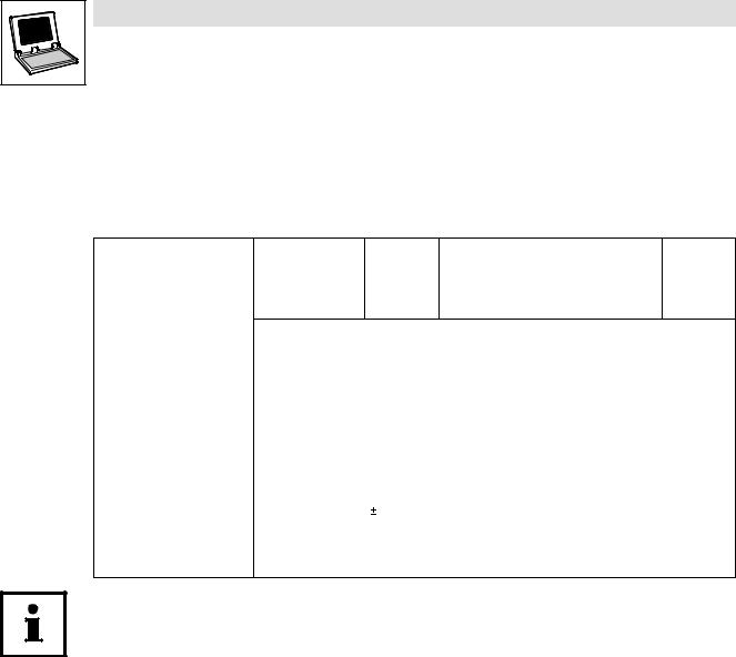
This Manual uses the following conventions to distinguish between different types of information:
Information type |
Distinction (in text) |
Example |
|
System block name |
bold |
The SB DIGITAL_IO... |
|
|
|
|
|
System (block) variable identifier |
italics |
The input DIGIN_bIn1_b... |
|
|
|
|
|
Tip!
Information about the conventions used for variable names of Lenze system blocks, function blocks and functions can be obtained from the appendix of the DDS online documentation "Introduction into IEC 61131−3 programming". The conventions ensure universal and uniform naming and support the readability of PLC programs.
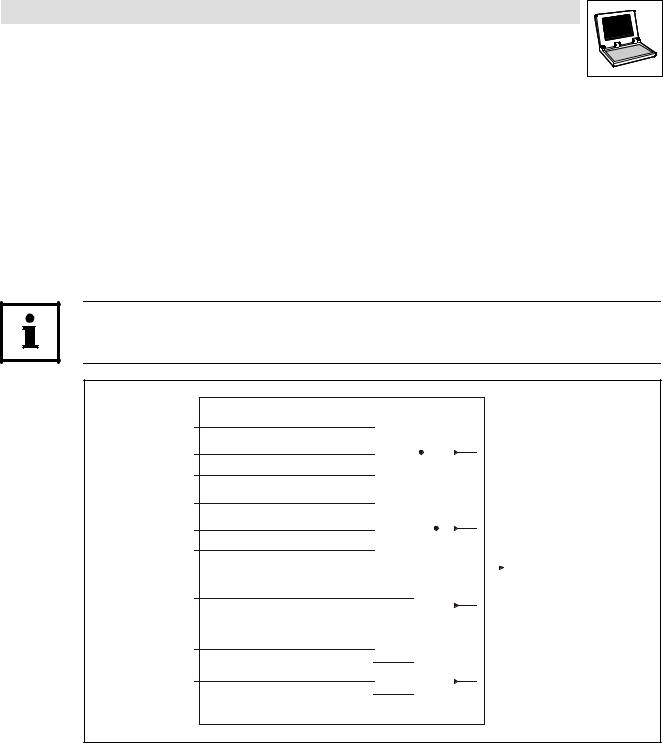
1.1.2System block descriptions
All system block descriptions given in this Manual have the same structure:
|
• |
Headline with SB identifier |
||
|
|
|
||
• ‚ |
‚ |
SB function and node number |
||
|
|
|
||
ƒ |
|
|
|
|
ƒ |
Short description of the SB and its most important features |
|||
|
||||
„ |
|
|
|
|
|
|
|
||
|
„ |
System block chart including all corresponding variables |
||
|
|
· |
Input variables |
|
… |
|
· |
Output variables |
|
|
|
|
||
|
|
|
||
|
… |
Table giving information about input and output variables: |
||
|
|
· |
Identifier |
|
|
|
· |
Data type |
|
|
|
· |
Signal type |
|
|
|
· |
Address |
|
† |
|
· |
Display code |
|
|
|
· |
Display format |
|
|
|
· |
Info |
|
|
|
|
||
|
† |
Detailed SB description |
||
|
|
|
|
|
l
9300 Servo PLC EN 5.1 |
1−1 |
9300 Servo PLC
Preface and general information
1.1.3Pictographs in this Manual
Pictographs |
Signal words |
|
used |
|
|
Warning of material |
Stop! |
Warns of potential damage to material. |
damage |
|
Possible consequences if disregarded: |
|
|
Damage of the PLC or its environment. |
More notes |
Tip! |
Indicates a tip or note. |
|
Note! |
|
1.1.4Terminology used
Term |
In this Manual used for |
|
|
AIF |
Automation interface |
DDS |
Drive PLC Developer Studio |
FIF |
Function interface |
|
|
GDC |
Global Drive Control (parameter setting program from Lenze) |
SB |
System block |
System bus |
System bus (CAN): Lenze standard bus system similar to CANopen |
1−2 |
9300 Servo PLC EN 5.1 |
l |
9300 Servo PLC
Preface and general information
1.2System block introduction
For a long time, Lenze has followed the principle of describing controller functions with the aid of function blocks (FBs). This principle can also be found in the IEC 61131−3 standard.
·Functions which can be used as software functions in projects are stored in function libraries as function blocks or functions.
·In addition, quasi−hardware functions are available as system blocks (SBs).
1.2.1System block principle
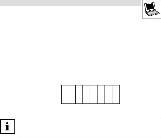
The system−block principle can be explained by means of a PLC system in a rack:
·The rack contains the CPU, digital I/Os, analog I/Os, counter card, positioning card, etc. as additional cards:
CPU x x x x x x
x = Additional cards
·The CPU can directly access the additional cards and process the resulting information.
·Additional cards have fixed addresses for access.
With Lenze PLC controllers, system blocks can be compared with these additional cards!
System blocks are special (hardware) function blocks permanently integrated into the run−time system of the PLC.
·SBs can address real hardware.
·SBs are assigned/identified through so−called node numbers. (^ 1−4)
·SB inputs and outputs are accessed via system variables or absolute memory addresses.
(^ 1−5)
·Inputs/outputs are always classified from the program’s point of view. (^ 1−6)
·Required SBs must be explicitly linked to the project via the control configuration of DDS.
(^ 1−7)
l
9300 Servo PLC EN 5.1 |
1−3 |

9300 Servo PLC
Preface and general information
1.2.2Node numbers
The system blocks of the 9300 Servo PLC carry the following node numbers:
Node number |
System block |
Notes |
1 |
DIGITAL_IO |
Digital inputs/outputs |
|
|
|
11 |
ANALOG1_IO |
Analog inputs/outputs 1 |
12 |
ANALOG2_IO |
Analog inputs/outputs 2 |
21 |
DFIN_IO_DigitalFrequency |
Digital frequency input |
|
|
|
22 |
DFOUT_IO_DigitalFrequency |
Digital frequency output |
|
|
|
31 |
CAN1_IO |
System bus (CAN)1 |
32 |
CAN2_IO |
|
33 |
CAN3_IO |
|
41 |
AIF1_IO_AutomationInterface |
Automation interface |
42 |
AIF2_IO_AutomationInterface |
|
43 |
AIF3_IO_AutomationInterface |
|
51 |
STATEBUS_IO |
State bus |
|
|
|
60 |
OSC_Oscilloscope |
Oscilloscope function |
101 |
CAN_Management |
System bus (CAN) management1 |
102 |
CAN_Syncronization |
System bus (CAN) synchronisation1 |
121 |
DCTRL_DriveControl |
Device control |
|
|
|
131 |
MCTRL_MotorControl |
Motor control |
141 |
FCODE_FreeCodes |
Free codes |
151 |
SYSTEM_FLAGS |
System flags |
|
|
|
161 |
AIF_IO_Management |
Automation interface management |
171 |
VAR_PERSISTENT |
Persistent variables |
181 |
MCTRL_AUX_HighResFeedback |
High−resolution encoder signal |
|
|
|
1 SBs for system bus (CAN) are described in the "System bus (CAN) for Lenze PLC devices" manual.
The node number is part of the absolute SB address (see chapter 2). (^ 1−5)
1−4 |
9300 Servo PLC EN 5.1 |
l |
9300 Servo PLC
Preface and general information
1.2.3Access via system variables
You can use the system variables of a system block in your project after the system block has been integrated into the control configuration of the DDS.
·Open the input assistance in the DDS editors via <F2> to get a listing of all available system variables:
· This Manual lists the system variables in the table for the corresponding system block:
Variable |
Data type |
Signal type |
Address |
Display |
Display |
Note |
|
|
|
|
code |
format |
|
|
|
|
|
|
|
|
DIGIN_bIn1_b |
|
|
%IX1.0.0 |
C0443/1 |
|
|
... |
Bool |
Binary |
... |
... |
bin |
|
DIGIN_bIn8_b |
|
|
%IX1.0.7 |
C0443/8 |
|
|
Example: Table with SB DIGITAL_IO inputs of the Drive PLC
1.2.4Access via absolute addresses
System block inputs and outputs can also be accessed via absolute addresses according to the IEC61131−3 standard:
For inputs use: |
For outputs use: |
|
|
|
a = node number |
%IXa.b.c |
%QXa.b.c |
b = word address |
|
|
c = bit address |
· This Manual lists the absolute addresses in the table for the corresponding system block:
Variable |
Data type |
Signal type |
Address |
Display |
Display |
Note |
|
|
|
|
code |
format |
|
|
|
|
|
|
|
|
DIGIN_bIn1_b |
|
|
%IX1.0.0 |
C0443/1 |
|
|
... |
Bool |
Binary |
... |
... |
bin |
|
DIGIN_bIn8_b |
|
|
%IX1.0.7 |
C0443/8 |
|
|
Example: Table with SB DIGITAL_IO inputs of the Drive PLC
l
9300 Servo PLC EN 5.1 |
1−5 |
1.2.5
Fig. 1−1
Fig. 1−2
1−6
9300 Servo PLC
Preface and general information
Definition of inputs/outputs
The application program is connected with the hardware by linking system blocks with program organisation units (POUs):
POU-Input POU-Output
|
|
|
|
|
|
|
|
|
|
|
|
|
SB-Output |
|
|
|
|
|
|
|
|
|
|
|
SB-Input |
|
|
|
|
|
|
|
|
|
|
|
||
|
|
|
|
|
|
|
|
|
|
|
|
|
|
|
|
|
|
|
|
|
|
|
|
|
|
|
|
|
|
|
|
|
|
|
|
|
|
|
|
|
|
|
|
|
|
|
|
|
|
|
|
|
|
|
|
|
|
|
|
|
|
|
|
|
SB |
|
|
|
POU |
|
|
|
SB |
|
|
|
|
|||||
|
|
|
|
|
|
|
|
|
|
|
|
|
|
|
|
|
|
|
|
|
|
|
|
|
|
|
Principle: Linking of system blocks with a program organisation unit (POU)
Tip!
Inputs and outputs are always classified from the program’s point of view.
·Logic SB inputs are hardware outputs of the PLC.
·Logic SB outputs are hardware inputs of the PLC.
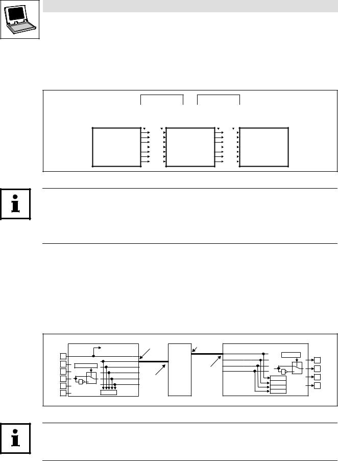
Example: System block DIGITAL_IO of the 9300 Servo PLC
If you want to use the digital input 1 and the digital output 1 of the 9300 Servo PLC, proceed as follows:
1.Link the SB DIGITAL_IO explicitly with the DDS control configuration. (^ 1−7)
2.Access to digital input 1:
Assign the system variable DIGIN_bIn1_b to a POU input.
3.Access to digital output 1:
Assign the system variable DIGOUT_bOut1_b to a POU output.
|
DIGIN |
|
DCTRL -X5/28 |
SB-OUT |
|
POU-OUT |
|
|
DIGOUT |
|
X5 |
|
|
|
|
|
|
|
|||
|
|
|
|
|
DIGOUT_bOut1_b |
|
|
|
||
|
|
|
DIGIN_bCInh_b |
|
|
|
|
|
X5 |
|
28 |
|
|
|
|
|
|
C0118/1...4 |
|||
|
|
DIGIN_bIn1_b |
|
|
|
DIGOUT_bOut2_b |
|
|
|
|
|
|
|
|
|
|
|
|
A1 |
||
|
|
|
|
|
|
|
|
|
||
|
|
|
|
|
|
|
|
|
|
|
E1 |
C0114/1...5 |
DIGIN_bIn2_b |
|
POU |
|
DIGOUT_bOut3_b |
|
0 |
|
|
|
|
SB-IN |
DIGOUT_bOut4_b |
|
|
A2 |
||||
E2 |
|
|
DIGIN_bIn3_b |
|
|
1 |
1 |
|||
|
0 |
|
|
|
|
|
|
|
||
|
|
DIGIN_bIn4_b |
|
|
|
|
|
|
|
|
E3 |
|
|
POU-IN |
|
|
|
C0444/1 |
|
A3 |
|
|
1 |
|
|
|
|
|
||||
1 |
DIGIN_bIn5_b |
|
|
|
|
|
||||
|
|
|
|
|
|
C0444/2 |
|
A4 |
||
E4 |
|
|
|
|
|
|
|
C0444/3 |
|
|
E5 |
|
|
C0443 |
|
|
|
|
C0444/4 |
|
|
|
|
|
|
|
|
|
|
|
||
Principle: Linking of the 9300 Servo PLC system block DIGITAL_IO with a POU
Tip!
According to the IEC61131−3 standard, only one copy of the digital input 1 and the digital output 1 may be transferred.
9300 Servo PLC EN 5.1 |
l |

9300 Servo PLC
Preface and general information
1.2.6Linking of system blocks with DDS
The system blocks required must be explicitly linked to the project via the control configuration of the DDS.
·The control configuration is placed as an object in the Resources tab in the Object organiser.
·The control configuration lists all inputs and outputs including the identifiers of the corresponding I/O variable, the absolute address and the data type of the I/O variable for every linked SB.
•Identifier of the I/O variable
‚ Absolute address
ƒ Data type of the I/O variable
|
• |
‚ |
ƒ |
|
|
|
|
Fig. 1−3 |
Example: Control configuration for 9300 Servo PLC with linked SB DIGITAL_IO |
|
|
Tip!
The control configuration provides a context menu for adding and deleting SBs which can be activated via the right mouse key.
l
9300 Servo PLC EN 5.1 |
1−7 |
1.2.7
1−8
9300 Servo PLC
Preface and general information
Signal types and scalings
Most inputs and outputs of Lenze function blocks/system blocks can be assigned to a certain signal type. We distinguish between digital, analog, position and speed signals.
The identifier of the corresponding input/output variable has an ending (starting with an underscore). It indicates the signal type.
Signal type |
Ending |
|
Memory |
Scaling |
Previous |
|
|
|
space |
(external value º internal value) |
identification |
|
|
|
|
|
|
Analog |
_a |
(analog) |
16 bits |
100 % º 16384 |
H |
Digital |
_b |
(binary) |
8 bits |
0 º FALSE; 1 º TRUE |
G |
Phase difference or speed |
_v |
(velocity) |
16 bits |
15000 rpm º 16384 |
F |
·Phase difference/speed ref. to 1 ms
·Scaling example:
|
|
|
|
|
|
|
|
|
|
|
|
|
15000 |
|
|
|
|
|
|
|
|
|
|
|
|
|
|
|
|
|
|
|||||||||
|
|
Speed (on motor side) + 15000 [rpm] + 60 [s] |
|
|
|
|
|
|
|
|
|
|
|
|
|
|
|
|
|
|
||||||||||||||||||||
|
|
1 motor revolution + 65536 [inc] |
|
|
|
|
|
|
|
|
|
|
|
|
|
|
|
|
|
|
||||||||||||||||||||
|
|
|
|
|
|
|
15000 |
|
|
|
|
|
|
|
|
|
|
15000 |
|
|
|
|
|
|
|
|
|
|
|
inc |
||||||||||
|
|
Variable value (..._v) + 60 [s] |
@ 65536 [inc] + |
|
|
|
|
|
|
@ 65536 [inc] + 16384 ms |
||||||||||||||||||||||||||||||
|
|
60000 [ms] |
||||||||||||||||||||||||||||||||||||||
Phase−angle or position |
_p |
(position) |
|
|
|
|
32 bits |
1 motor revolution º 65536 |
|
|
|
|
|
|
|
|
|
|
E |
|||||||||||||||||||||
|
|
|
|
|
|
|
|
|
|
|
|
|
|
|
|
|
|
|
|
|
|
|
|
|
|
|
|
|
|
|
|
|
|
|
|
|
|
|
|
|
|
|
|
|
|
|
|
|
|
|
|
|
|
|
|
|
|
|
|
|
|
|
|
|
|
|
|
|
|
|
|
||||||||||
|
|
|
|
|
|
|
|
|
|
|
|
|
|
|
|
|
|
|
|
|
|
|
|
|
|
|||||||||||||||
|
|
|
|
|
|
|
|
|
|
|
|
|
|
|
|
|
|
|
|
|
|
|
|
|
|
|
|
|
|
|
|
|
|
|
|
|
|
|
|
|
|
|
|
|
|
|
|
|
|
|
|
|
|
|
|
|
|
|
|
|
|
|
|
|
|
|
|
|
|
|
|
|
|
|
|
|
|
|
|
|
|
|
|
31 |
|
|
|
|
High Word |
|
|
|
|
|
|
|
Low Word |
0 |
|
|
|
|||||||||||||||||||||
|
|
|
|
|
|
|||||||||||||||||||||||||||||||||||
|
|
|
• Direction (0 º clockwise rotation; 1 º counter−clockwise rotation) |
|||||||||||||||||||||||||||||||||||||
|
|
|
‚No. of motor revolutions (0 ... 32767) |
|
|
|
|
|
|
|
|
|
|
|
|
|||||||||||||||||||||||||
|
|
|
ƒ Phase angle or position (0 ... 65535) |
|
|
|
|
|
|
|
|
|
|
|
|
|||||||||||||||||||||||||
|
|
|
|
|
|
|
|
|
|
|
|
|
|
|
|
|
|
|
|
|
|
|
|
|
|
|
|
|
|
|
|
|
|
|
|
|
|
|
|
|
Note!
Due to their scaling, analog signals have an asymmetrical resolution range (−200 % ... +199.99 %):
External value: |
−200 % |
−100 % |
0 |
+100 % |
+199.99 % |
Internal value: |
−32768 |
−16384 |
0 |
+16384 |
+32767 |
|
|
|
|
|
|
9300 Servo PLC EN 5.1 |
l |

9300 Servo PLC
System blocks
2 System blocks
The following sections inform about the system blocks of the basic unit.
L
9300 Servo PLC EN 5.1 |
2−9 |
9300 Servo PLC
System blocks
2.1AIF1_IO_AutomationInterface (node number 41)
2.1AIF1_IO_AutomationInterface (node number 41)
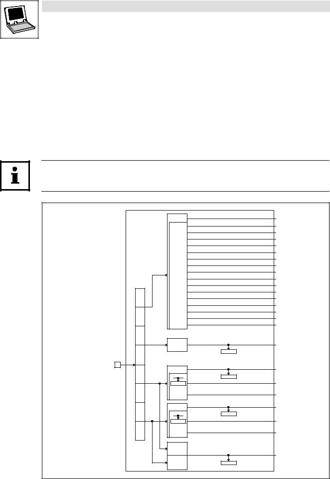
2.1.1Inputs_AIF1
This SB is used as an interface for input signals (e.g. setpoints/actual values) from attached fieldbus modules (e.g. INTERBUS, PROFIBUS−DP).
·The process image is
–created in the cyclic task in a fixed time interval of 10 ms.
–created in an interval task within the time set for this task.
–read at the beginning of the task and written at its end.
Tip!
Please observe the Operating Instructions for the attached fieldbus module.
Inputs_AIF1
16 Bit
16 binary signals
Controlword |
Byte |
1 |
|
|
Byte |
|
2 |
Byte |
|
|
3 |
|
|
|
16 Bit |
|
Byte |
|
|
4 |
|
|
Automation |
|
|
Interface |
|
|
Byte |
16 Bit |
|
|
||
5 |
|
|
|
C0855/1 |
|
Byte |
16 binary |
|
signals |
||
6 |
||
|
||
Byte |
16 Bit |
|
|
||
7 |
|
|
|
C0855/2 |
|
Byte |
16 binary |
|
signals |
||
8 |
||
|
||
|
16 Bit |
|
|
LowWord |
|
|
16 Bit |
|
|
HighWord |
AIF1_wDctrlCtrl
AIF1_bCtrlB0_b
AIF1_bCtrlB1_b
AIF1_bCtrlB2_b
AIF1_bCtrlQuickstop_b
AIF1_bCtrlB4_b
AIF1_bCtrlB5_b
AIF1_bCtrlB6_b
AIF1_bCtrlB7_b
AIF1_bCtrlDisable_b
AIF1_bCtrlCInhibit_b
AIF1_bCtrlTripSet_b
AIF1_bCtrlTripReset_b
AIF1_bCtrlB12_b
AIF1_bCtrlB13_b
AIF1_bCtrlB14_b
AIF1_bCtrlB15_b
AIF1_nInW1_a
C0856/1
AIF1_nInW2_a
C0856/2
AIF1_bInB0_b
… AIF1_bInB15_b
AIF1_nInW3_a
C0856/3
AIF1_bIn16_b
…
AIF1_bIn31_b
AIF1_dnInD1_p
C0857
Fig. 2−1 |
Inputs_AIF1 |
2−10 |
9300 Servo PLC EN 5.1 |
L |

|
9300 Servo PLC |
|
System blocks |
2.1 |
AIF1_IO_AutomationInterface (node number 41) |
System variables
Variable |
Data type |
Signal type |
Address |
Display |
Display |
Note |
|
|
|
|
code |
format |
|
|
|
|
|
|
|
|
AIF1_wDctrlCtrl |
Word |
− |
%IX41.0 |
C0136/3 |
hex |
|
|
|
|
|
|
|
|
AIF1_bCtrlB0_b |
|
|
%IX41.0.0 |
|
|
|
AIF1_bCtrlB1_b |
|
|
%IX41.0.1 |
|
|
|
|
|
|
|
|
|
|
AIF1_bCtrlB2_b |
|
|
%IX41.0.2 |
|
|
|
AIF1_bCtrlQuickstop_b |
|
|
%IX41.0.3 |
|
|
|
AIF1_bCtrlB4_b |
|
|
%IX41.0.4 |
|
|
|
|
|
|
|
|
|
|
AIF1_bCtrlB5_b |
|
|
%IX41.0.5 |
|
|
|
AIF1_bCtrlB6_b |
|
|
%IX41.0.6 |
|
|
|
AIF1_bCtrlB7_b |
Bool |
Binary |
%IX41.0.7 |
C0136/3 |
bin |
|
|
|
|
||||
AIF1_bCtrlDisable_b |
%IX41.0.8 |
|
||||
|
|
|
|
|
||
AIF1_bCtrlCInhibit_b |
|
|
%IX41.0.9 |
|
|
|
|
|
|
|
|
|
|
AIF1_bCtrlTripSet_b |
|
|
%IX41.0.10 |
|
|
|
AIF1_bCtrlTripReset_b |
|
|
%IX41.0.11 |
|
|
|
AIF1_bCtrlB12_b |
|
|
%IX41.0.12 |
|
|
|
|
|
|
|
|
|
|
AIF1_bCtrlB13_b |
|
|
%IX41.0.13 |
|
|
|
AIF1_bCtrlB14_b |
|
|
%IX41.0.14 |
|
|
|
AIF1_bCtrlB15_b |
|
|
%IX41.0.15 |
|
|
|
|
|
|
|
|
|
|
AIF1_nInW1_a |
|
|
%IW41.1 |
C0856/1 |
|
|
AIF1_nInW2_a |
Integer |
Analog |
%IW41.2 |
C0856/2 |
dec [%] |
|
AIF1_nInW3_a |
|
|
%IW41.3 |
C0856/3 |
|
|
|
|
|
|
|
|
|
AIF1_bInB0_b |
|
|
%IX41.2.0 |
|
|
|
... |
|
|
... |
C0855/1 |
|
|
AIF1_bInB15_b |
Bool |
Binary |
%IX41.2.15 |
|
hex |
|
AIF1_bInB16_b |
%IX41.3.0 |
|
|
|||
|
|
|
|
|
||
... |
|
|
... |
C0855/2 |
|
|
AIF1_bInB31_b |
|
|
%IX41.3.15 |
|
|
|
AIF1_dnInD1_p |
Double integer |
Position |
%ID41.1 |
C0857 |
dec [inc] |
|
L
9300 Servo PLC EN 5.1 |
2−11 |

2.1 |
9300 Servo PLC
System blocks
AIF1_IO_AutomationInterface (node number 41)
User data
The received 8 bytes of user data are assigned to several variables of different data types simultaneously. Thus the data can be evaluated in the PLC program as
·binary information (1 bit)
·control word/quasi−analog value (16 bits)
·phase information (32 bits)
according to the requirements.
Byte |
|
|
Variable (1 bit) |
Variable (16 bits) |
Variable (32 bits) |
|
|
|
|
|
|
1, 2 |
|
|
AIF1_bInB0_b |
|
|
|
|
|
AIF1_bInB1_b |
|
|
|
|
|
AIF1_bInB2_b |
|
|
|
|
AIF1_bCtrlQuickstop_b |
|
|
|
|
|
|
AIF1_bInB4_b |
|
|
|
|
... |
|
|
|
|
|
|
AIF1_bInB7_b |
AIF1_wDctrlCtrl |
|
|
|
AIF1_bCtrlDisable_b |
|
||
|
|
|
|
||
|
|
AIF1_bCtrlCInhibit_b |
|
|
|
|
|
AIF1_bCtrlTripSet_b |
|
|
|
|
|
AIF1_bCtrlTripReset_b |
|
|
|
|
|
|
AIF1_bInB12_b |
|
|
|
|
... |
|
|
|
|
|
|
AIF1_bInB15_b |
|
|
|
Notes: |
|
Drive PLC: |
|
|
|
|
|
All variables assigned to byte 1/2 can be freely used in the PLC program. |
|
|
|
|
|
9300 Servo PLC: |
|
|
|
|
|
The assignment of the controller−internal control word to byte 1/2 is not a fixed assignment. |
||
|
|
|
· Byte 1/2 can, however, be used to write the signals for the quick stop (QSP), DISABLE, CINH, TRIP−SET and |
||
|
|
|
TRIP−RESET functions to the SB DCTRL_DriveControl. |
|
|
|
|
|
– To do this, connect the variable AIF1_wDctrlCtrl with the variable DCTRL_wAIF1Ctrl of the SB |
||
|
|
|
DCTRL_DriveControl. |
|
|
|
|
|
· The signals can also be read and processed via the following variables: |
|
|
|
|
|
– AIF1_bCtrlQuickstop_b |
|
|
|
|
|
– AIF1_bCtrlDisable_b |
|
|
|
|
|
– AIF1_bCtrlCInhibit_b |
|
|
|
|
|
– AIF1_bCtrlTripSet_b |
|
|
|
|
|
– AIF1_bCtrlTripReset_b |
|
|
3, 4 |
|
|
|
|
|
|
|
|
|
AIF1_nInW1_a |
|
|
|
|
|
|
|
5, 6 |
|
|
AIF1_bInB0_b |
|
|
|
|
... |
AIF1_nInW2_a |
|
|
|
|
|
AIF1_bInB15_b |
|
AIF1_dnInD1_p |
7, 8 |
|
|
AIF1_bInB16_b |
|
|
|
|
|
|
||
|
|
... |
AIF1_nInW3_a |
|
|
|
|
|
AIF1_bInB31_b |
|
|
2−12 |
9300 Servo PLC EN 5.1 |
L |
|
9300 Servo PLC |
|
System blocks |
2.1 |
AIF1_IO_AutomationInterface (node number 41) |
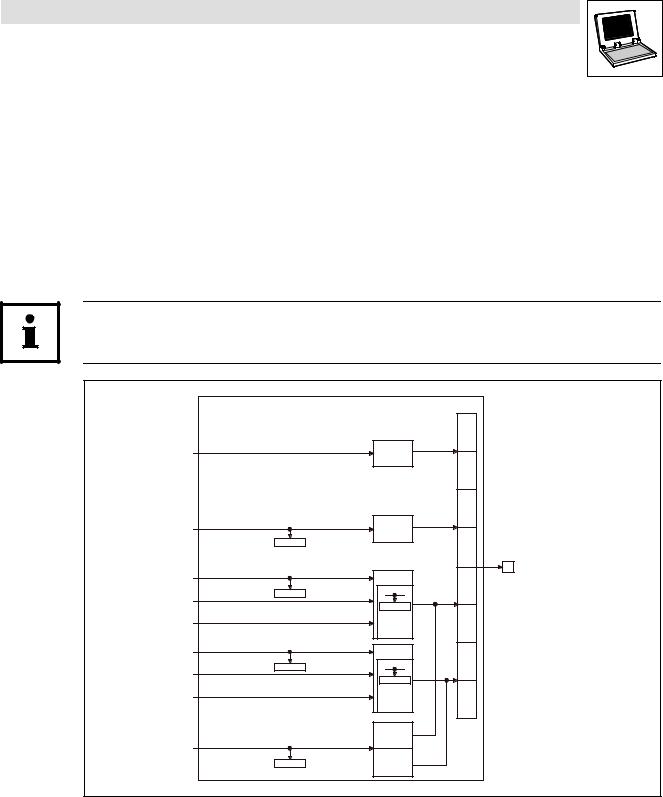
2.1.2Outputs_AIF1
This SB is used as an interface for output signals (e.g. setpoints/actual values) to attached fieldbus modules (e.g. INTERBUS, PROFIBUS−DP).
·The process image is
–created in the cyclic task in a fixed time interval of 10 ms.
–created in an interval task within the time set for this task.
–read at the beginning of the task and written at its end.
Tip!
Please observe the Operating Instructions for the attached fieldbus module.
AIF1_wDctrlStat
AIF1_nOutW1_a
C0858/1
AIF1_nOutW2__a
AIF1_bFDO0_b C0858/2
…
AIF1_bFDO15_b
AIF1_nOutW3_a
AIF1_bFDO16_b C0858/3
…
AIF1_bFDO31_b
AIF1_dnOutD1_p
C0859
|
Outputs_AIF1 |
|
|
Byte |
|
|
1 |
|
16 Bit |
|
|
|
Byte |
|
|
2 |
|
|
Byte |
|
|
3 |
|
16 Bit |
|
|
|
Byte |
|
|
4 |
|
|
Automation |
|
|
Interface |
|
16 Bit |
Byte |
|
|
||
|
5 |
|
C0151/4 |
|
|
16 binary |
Byte |
|
signals |
6 |
|
16 Bit |
Byte |
|
|
||
|
7 |
|
C0151/4 |
|
|
16 binary |
Byte |
|
signals |
||
8 |
||
|
||
16 Bit |
|
|
LowWord |
|
|
16 Bit |
|
|
HighWord |
|
Fig. 2−2 |
Outputs_AIF1 |
L
9300 Servo PLC EN 5.1 |
2−13 |

2.1 |
9300 Servo PLC
System blocks
AIF1_IO_AutomationInterface (node number 41)
System variables
Variable |
Data type |
Signal type |
Address |
Display |
Display |
Note |
|
|
|
|
|
code |
format |
|
|
|
|
|
|
|
|
|
|
AIF1_wDctrlStat |
Word |
− |
%QW41.0 |
− |
− |
|
|
|
|
|
|
|
|
|
|
AIF1_nOutW1_a |
|
|
%QW41.1 |
C0858/1 |
|
|
|
AIF1_nOutW2_a |
Integer |
Analog |
%QW41.2 |
C0858/2 |
dec [%] |
|
|
AIF1_nOutW3_a |
|
|
%QW41.3 |
C0858/3 |
|
|
|
AIF1_bFDO0_b |
|
|
%QX41.2.0 |
|
|
|
|
.. |
|
|
... |
|
|
|
|
AIF1_bFDO15_b |
Bool |
Binary |
%QX41.2.15 |
C0151/4 |
hex |
Display code in hex |
|
AIF1_bFDO16_b |
%QX41.3.0 |
as double word |
|||||
|
|
|
|
||||
.. |
|
|
... |
|
|
|
|
AIF1_bFDO31_b |
|
|
%QX41.3.15 |
|
|
|
|
AIF1_dnOutD1_p |
Double integer |
Position |
%QD41.1 |
C0859 |
dec [inc] |
|
User data
The 8 bytes of user data to be sent can be written to via several variables of different data types simultaneously. Thus the data can be transferred by the PLC program as
·binary information (1 bit)
·status word/quasi−analog value (16 bits)
·phase information (32 bits)
according to the requirements.
Byte |
|
Variable (1 bit) |
Variable (16 bits) |
|
Variable (32 bits) |
|
1, 2 |
|
|
|
|
|
|
|
|
|
AIF1_wDctrlStat |
|
|
|
|
|
|
|
|
|
|
|
Notes: |
Drive PLC: |
|
|
|
|
|
|
All variables assigned to byte 1/2 can be written to by the PLC program. |
|
|
||
|
|
9300 Servo PLC: |
|
|
|
|
|
|
Bytes 1 and 2 can be used to transfer the status word from the SB DCTRL_DriveControl. |
|
|
||
|
|
· To do this, connect the variable DCTRL_wStat of the SB DCTRL_DriveControl with the variable AIF1_wDctrlStat. |
||||
|
|
· In addition to signals such as IMP and CINH, the SB DCTRL_DriveControl status word contains some freely |
||||
|
|
assignable signals which can be written to via the variables DCTRL_bStateB.._b of the SB DCTRL_DriveControl. |
||||
3, 4 |
|
|
|
|
|
|
|
|
|
AIF1_nOutW1_a |
|
|
|
|
|
|
|
|
|
|
5, 6 |
|
AIF1_bFDO0_b |
|
|
|
|
|
|
... |
AIF1_nOutW2_a |
|
|
|
|
|
AIF1_bFDO15_b |
|
|
AIF1_dnOutD1_p |
|
7, 8 |
|
AIF1_bFDO16_b |
|
|
||
|
|
|
|
|
||
|
|
... |
AIF1_nOutW3_a |
|
|
|
|
|
AIF1_bFDO31_b |
|
|
|
|
|
|
|
|
|
|
|
Tip!
Avoid simultaneous overwriting via different variable types to ensure data consistency.
·Thus bytes 5 and 6 should only be written to
–by the variable AIF1_dnOutD1_p,
–by the variable AIF1_nOutW2_a or
–by the variables AIF1_bFDO0_b ... AIF1_bFDO15_b.
2−14 |
9300 Servo PLC EN 5.1 |
L |
|
9300 Servo PLC |
|
System blocks |
2.2 |
AIF2_IO_AutomationInterface (node number 42) |
2.2AIF2_IO_AutomationInterface (node number 42)
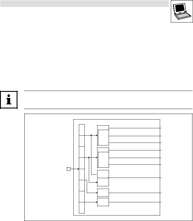
2.2.1Inputs_AIF2
Automation interface (node number 42)
This SB is used as an interface for input signals (e.g. setpoints/actual values) from attached fieldbus modules (e.g. INTERBUS, PROFIBUS−DP).
·The process image is
–created in the cyclic task in a fixed time interval of 10 ms.
–created in an interval task within the time set for this task.
–read at the beginning of the task and written at its end.
Tip!
Please observe the Operating Instructions for the attached fieldbus module.
Inputs_AIF2
16 Bit
Byte
1
16 binary
signals
Byte 2
16 Bit
Byte
3
16 binary
signals
Byte 4
Automation
Interface
16 Bit
Byte  LowWord
5
16 Bit
HighWord
Byte
6
16 Bit
Byte
7
16 Bit
Byte
8
AIF2_nInW1_a
AIF2_bInB0_b
...
AIF2_bInB15_b
AIF2_nInW2_a
AIF2_bInB16_b
...
AIF2_bInB31_b
AIF2_dnInD1_p
AIF2_nInW3_a
AIF2_nInW4_a
Fig. 2−3 |
Inputs_AIF2 |
L
9300 Servo PLC EN 5.1 |
2−15 |

2.2 |
9300 Servo PLC
System blocks
AIF2_IO_AutomationInterface (node number 42)
System variables
Variable |
Data type |
Signal type |
Address |
Display code |
Display |
Note |
|
|
|
|
|
format |
|
|
|
|
|
|
|
|
AIF2_nInW1_a |
|
|
%IW42.0 |
|
|
|
|
|
|
|
|
|
|
AIF2_nInW2_a |
Integer |
Analog |
%IW42.1 |
|
|
|
AIF2_nInW3_a |
%IW42.2 |
|
|
|
||
|
|
|
|
|
||
|
|
|
|
|
|
|
AIF2_nInW4_a |
|
|
%IW42.3 |
|
|
|
|
|
|
|
|
|
|
AIF2_bInB0_b |
|
|
%IX42.0.0 |
|
|
|
... |
|
|
... |
|
|
|
AIF2_bInB15_b |
Bool |
Binary |
%IX42.0.15 |
|
|
|
AIF2_bInB16_b |
%IX42.1.0 |
|
|
|
||
|
|
|
|
|
||
... |
|
|
... |
|
|
|
AIF2_bInB31_b |
|
|
%IX42.1.15 |
|
|
|
AIF2_dnInD1_p |
Double integer |
Position |
%ID42.0 |
|
|
|
User data
The 4 first bytes of the received 8 bytes of user data are assigned to several variables of different data types simultaneously. Thus the data can be evaluated in the PLC program as
·binary information (1 bit)
·quasi−analog value (16 bits)
·angle information (32 bits)
according to the requirements.
Byte |
Variable (1 bit) |
Variable (16 bits) |
Variable (32 bits) |
1, 2 |
AIF2_bInB0_b |
|
|
|
... |
AIF2_nInW1_a |
|
|
AIF2_bInB15_b |
|
AIF2_dnInD1_p |
3, 4 |
AIF2_bInB16_b |
|
|
|
|
||
|
... |
AIF2_nInW2_a |
|
|
AIF2_bInB31_b |
|
|
5, 6 |
|
|
|
|
|
AIF2_nInW3_a |
|
|
|
|
|
7, 8 |
|
|
|
|
|
AIF2_nInW4_a |
|
|
|
|
|
2−16 |
9300 Servo PLC EN 5.1 |
L |

|
9300 Servo PLC |
|
System blocks |
2.2 |
AIF2_IO_AutomationInterface (node number 42) |
2.2.2Outputs_AIF2
This SB is used as an interface for output signals (e.g. setpoints/actual values) to attached fieldbus modules (e.g. INTERBUS, PROFIBUS−DP).
·The process image is
–created in the cyclic task in a fixed time interval of 10 ms.
–created in an interval task within the time set for this task.
–read at the beginning of the task and written at its end.
Tip!
Please observe the Operating Instructions for the attached fieldbus module.
AIF2_nOutW1_a
AIF2_bFDO0_b
...
AIF2_bFDO15_b
AIF2_nOutW2_a
AIF2_bFDO16_b
...
AIF2_bFDO31_b
AIF2_dnOutD1_p
AIF2_nOutW3_a
AIF2_nOutW4_a
Outputs_AIF2
|
|
|
|
|
|
|
|
|
|
|
16 Bit |
|
|
|
|
|
Byte |
|
|
|
|
|
|
|
|
|
|
|
|
|||
|
|
|
|
|
|
|
1 |
|
|
|
16 binary |
|
|
|
|
|
|
|
|
|
|
|
|
|
|
|
|
|
|
|
|
|
signals |
|
|
|
|
|
|
Byte |
|
|
|
|
|
|
|
|
|
|
|
|||
|
|
|
|
|
|
|
2 |
|
|
|
|
|
|
|
|
|
|
|
|
|
|
|
|
|
|
|
|
|
|
|
|
|
|
|
|
|
|
|
|
|
|
||
16 Bit |
|
|
|
|
|
Byte |
|
|
|
|
|
|
|
|
|
|
|
|
|||
|
|
|
|
|
|
|
3 |
|
|
|
16 binary |
|
|
|
|
|
|
|
|
|
|
|
|
|
|
|
|
|
|
|
||
signals |
|
|
|
|
|
Byte |
|
|
|
|
|
|
|
|
|
|
|
|
|||
|
|
|
|
|
|
|
4 |
|
|
|
|
|
|
|
|
|
|
|
|
|
Automation |
|
|
|
|
|
|
|
|
|
|
|
|
|
|
|
|
|
|
|
|
|
Interface |
16 Bit |
|
|
|
|
Byte |
|
|
|
||
LowWord |
|
|
|
|
|
|
||||
|
|
|
|
|
|
|
|
|||
|
|
|
|
5 |
|
|
|
|||
|
|
|
|
|
|
|
|
|
|
|
16 Bit |
|
|
|
|
|
|
|
|
|
|
|
|
|
|
|
||||||
HighWord |
|
|
|
|
|
Byte |
|
|
|
|
|
|
|
|
|
|
|
|
|||
|
|
|
|
|
|
|
|
|||
|
|
|
|
|
|
|
6 |
|
|
|
|
|
|
|
|
|
|
|
|
|
|
16 Bit |
|
|
|
|
|
|
|
|
|
|
|
|
|
|
|
Byte |
|
|
|
||
|
|
|
|
|
|
|
|
|||
|
|
|
|
|
|
|
|
|||
|
|
|
|
|
|
|
7 |
|
|
|
16 Bit |
|
|
|
|
Byte |
|
|
|
||
|
|
|
|
|
|
|
|
|||
|
|
|
|
|
|
|
|
|||
|
|
|
|
|
|
|
|
|
|
|
|
|
|
|
|
|
|
8 |
|
|
|
|
|
|
|
|
|
|
|
|
|
|
Fig. 2−4 |
Outputs_AIF2 |
L
9300 Servo PLC EN 5.1 |
2−17 |

2.2 |
9300 Servo PLC
System blocks
AIF2_IO_AutomationInterface (node number 42)
System variables
Variable |
Data type |
Signal type |
Address |
Display code |
Display |
Note |
|
|
|
|
|
format |
|
|
|
|
|
|
|
|
AIF2_nOutW1_a |
|
|
%QW42.0 |
|
|
|
|
|
|
|
|
|
|
AIF2_nOutW2_a |
Integer |
Analog |
%QW42.1 |
|
|
|
AIF2_nOutW3_a |
%QW42.2 |
|
|
|
||
|
|
|
|
|
||
|
|
|
|
|
|
|
AIF2_nOutW4_a |
|
|
%QW42.3 |
|
|
|
|
|
|
|
|
|
|
AIF2_bFDO0_b |
|
|
%QX42.0.0 |
|
|
|
... |
|
|
... |
|
|
|
AIF2_bFDO15_b |
Bool |
Binary |
%QX42.0.15 |
|
|
|
AIF2_bFDO16_b |
%QX42.1.0 |
|
|
|
||
|
|
|
|
|
||
... |
|
|
... |
|
|
|
AIF2_bFDO31_b |
|
|
%QX42.1.15 |
|
|
|
AIF2_dnOutD1_p |
Double integer |
Position |
%QD42.0 |
|
|
|
User data
The first 4 bytes of the 8 bytes of user data to be sent can be written to via several variables of different data types at the same time. Data can therefore be transferred by the PLC program as
·binary information (1 bit)
·quasi−analog value (16 bits)
·angle information (32 bits)
according to the requirements.
Byte |
Variable (1 bit) |
Variable (16 bits) |
Variable (32 bits) |
|
1, 2 |
AIF2_bFDO0_b |
|
|
|
|
... |
AIF2_nOutW1_a |
|
|
|
AIF2_bFDO15_b |
|
AIF2_dnOutD1_p |
|
3, 4 |
AIF2_bFDO16_b |
|
||
|
|
|
||
|
... |
AIF2_nOutW2_a |
|
|
|
AIF2_bFDO31_b |
|
|
|
5, 6 |
|
|
|
|
|
|
AIF2_nOutW3_a |
|
|
|
|
|
|
|
7, 8 |
|
|
|
|
|
|
AIF2_nOutW4_a |
|
|
|
|
|
|
|
|
|
|
|
|
Tip!
Avoid simultaneous overwriting via different variable types to ensure data consistency.
·Thus bytes 1 and 2 should only be written to
–by the variable AIF2_dnOutD1_p,
–by the variable AIF2_nOutW1_a or
–by the variables AIF2_bFDO0_b ... AIF2_bFDO15_b.
2−18 |
9300 Servo PLC EN 5.1 |
L |
|
9300 Servo PLC |
|
System blocks |
2.3 |
AIF3_IO_AutomationInterface (node number 43) |
2.3AIF3_IO_AutomationInterface (node number 43)
2.3.1Inputs_AIF3
This SB is used as an interface for input signals (e.g. setpoints/actual values) from attached fieldbus modules (e.g. INTERBUS, PROFIBUS−DP).
·The process image is
–created in the cyclic task in a fixed time interval of 10 ms.
–created in an interval task within the time set for this task.
–read at the beginning of the task and written at its end.
Tip!
Please observe the Operating Instructions for the attached fieldbus module.
Inputs_AIF3
16 Bit
Byte
1
16 binary
signals
Byte 2
16 Bit
Byte
3
16 binary
signals
Byte 4
Automation
Interface
16 Bit
Byte  LowWord
5
16 Bit
HighWord
Byte
6
16 Bit
Byte
7
16 Bit
Byte
8
AIF3_nInW1_a
AIF3_bInB0_b
...
AIF3_bInB15_b
AIF3_nInW2_a
AIF3_bInB16_b
...
AIF3_bInB31_b
AIF3_dnInD1_p
AIF3_nInW3_a
AIF3_nInW4_a
Fig. 2−5 |
Inputs_AIF3 |
L
9300 Servo PLC EN 5.1 |
2−19 |

2.3 |
9300 Servo PLC
System blocks
AIF3_IO_AutomationInterface (node number 43)
System variables
Variable |
Data type |
Signal type |
Address |
Display code |
Display |
Note |
|
|
|
|
|
format |
|
|
|
|
|
|
|
|
AIF3_nInW1_a |
|
|
%IW43.0 |
|
|
|
|
|
|
|
|
|
|
AIF3_nInW2_a |
Integer |
Analog |
%IW43.1 |
|
|
|
AIF3_nInW3_a |
%IW43.2 |
|
|
|
||
|
|
|
|
|
||
|
|
|
|
|
|
|
AIF3_nInW4_a |
|
|
%IW43.3 |
|
|
|
|
|
|
|
|
|
|
AIF3_bInB0_b |
|
|
%IX43.0.0 |
|
|
|
... |
|
|
... |
|
|
|
AIF3_bInB15_b |
Bool |
Binary |
%IX43.0.15 |
|
|
|
AIF3_bInB16_b |
%IX43.1.0 |
|
|
|
||
|
|
|
|
|
||
... |
|
|
... |
|
|
|
AIF3_bInB31_b |
|
|
%IX43.1.15 |
|
|
|
AIF3_dnInD1_p |
Double integer |
Position |
%ID43.0 |
|
|
|
User data
The 4 first bytes of the received 8 bytes of user data are assigned to several variables of different data types simultaneously. Thus the data can be evaluated in the PLC program as
·binary information (1 bit)
·quasi−analog value (16 bits)
·angle information (32 bits)
according to the requirements.
Byte |
Variable (1 bit) |
Variable (16 bits) |
Variable (32 bits) |
1, 2 |
AIF3_bInB0_b |
|
|
|
... |
AIF3_nInW1_a |
|
|
AIF3_bInB15_b |
|
AIF3_dnInD1_p |
3, 4 |
AIF3_bInB16_b |
|
|
|
|
||
|
... |
AIF3_nInW2_a |
|
|
AIF3_bInB31_b |
|
|
5, 6 |
|
|
|
|
|
AIF3_nInW3_a |
|
|
|
|
|
7, 8 |
|
|
|
|
|
AIF3_nInW4_a |
|
|
|
|
|
2−20 |
9300 Servo PLC EN 5.1 |
L |
|
9300 Servo PLC |
|
System blocks |
2.3 |
AIF3_IO_AutomationInterface (node number 43) |
2.3.2Outputs_AIF3
This SB is used as an interface for output signals (e.g. setpoints/actual values) to attached fieldbus modules (e.g. INTERBUS, PROFIBUS−DP).
·The process image is
–created in the cyclic task in a fixed time interval of 10 ms.
–created in an interval task within the time set for this task.
–read at the beginning of the task and written at its end.
Tip!
Please observe the Operating Instructions for the attached fieldbus module.
AIF3_nOutW1_a
AIF3_bFDO0_b
...
AIF3_bFDO15_b
AIF3_nOutW2_a
AIF3_bFDO16_b
...
AIF3_bFDO31_b
AIF3_dnOutD1_p
AIF3_nOutW3_a
AIF3_nOutW4_a
Outputs_AIF3
|
|
|
|
|
|
|
|
|
|
|
16 Bit |
|
|
|
|
|
Byte |
|
|
|
|
|
|
|
|
|
|
|
|
|||
|
|
|
|
|
|
|
1 |
|
|
|
16 binary |
|
|
|
|
|
|
|
|
|
|
|
|
|
|
|
|
|
|
|
|
|
signals |
|
|
|
|
|
|
Byte |
|
|
|
|
|
|
|
|
|
|
|
|||
|
|
|
|
|
|
|
2 |
|
|
|
|
|
|
|
|
|
|
|
|
|
|
|
|
|
|
|
|
|
|
|
|
|
|
|
|
|
|
|
|
|
|
||
16 Bit |
|
|
|
|
|
Byte |
|
|
|
|
|
|
|
|
|
|
|
|
|||
|
|
|
|
|
|
|
3 |
|
|
|
16 binary |
|
|
|
|
|
|
|
|
|
|
|
|
|
|
|
|
|
|
|
||
signals |
|
|
|
|
|
Byte |
|
|
|
|
|
|
|
|
|
|
|
|
|||
|
|
|
|
|
|
|
4 |
|
|
|
|
|
|
|
|
|
|
|
|
|
Automation |
|
|
|
|
|
|
|
|
|
|
|
|
|
|
|
|
|
|
|
|
|
Interface |
16 Bit |
|
|
|
|
Byte |
|
|
|
||
LowWord |
|
|
|
|
|
|
||||
|
|
|
|
|
|
|
|
|||
|
|
|
|
5 |
|
|
|
|||
|
|
|
|
|
|
|
|
|
|
|
16 Bit |
|
|
|
|
|
|
|
|
|
|
|
|
|
|
|
||||||
HighWord |
|
|
|
|
|
Byte |
|
|
|
|
|
|
|
|
|
|
|
|
|||
|
|
|
|
|
|
|
|
|||
|
|
|
|
|
|
|
6 |
|
|
|
|
|
|
|
|
|
|
|
|
|
|
16 Bit |
|
|
|
|
|
|
|
|
|
|
|
|
|
|
|
Byte |
|
|
|
||
|
|
|
|
|
|
|
|
|||
|
|
|
|
|
|
|
|
|||
|
|
|
|
|
|
|
7 |
|
|
|
16 Bit |
|
|
|
|
Byte |
|
|
|
||
|
|
|
|
|
|
|
|
|||
|
|
|
|
|
|
|
|
|||
|
|
|
|
|
|
|
|
|
|
|
|
|
|
|
|
|
|
8 |
|
|
|
|
|
|
|
|
|
|
|
|
|
|
Fig. 2−6 |
Outputs_AIF3 |
L
9300 Servo PLC EN 5.1 |
2−21 |

2.3 |
9300 Servo PLC
System blocks
AIF3_IO_AutomationInterface (node number 43)
System variables
Variable |
Data type |
Signal type |
Address |
Display code |
Display |
Note |
|
|
|
|
|
format |
|
|
|
|
|
|
|
|
AIF3_nOutW1_a |
|
|
%QW43.0 |
|
|
|
|
|
|
|
|
|
|
AIF3_nOutW2_a |
Integer |
Analog |
%QW43.1 |
|
|
|
AIF3_nOutW3_a |
%QW43.2 |
|
|
|
||
|
|
|
|
|
||
|
|
|
|
|
|
|
AIF3_nOutW4_a |
|
|
%QW43.3 |
|
|
|
|
|
|
|
|
|
|
AIF3_bFDO0_b |
|
|
%QX43.0.0 |
|
|
|
... |
|
|
... |
|
|
|
AIF3_bFDO15_b |
Bool |
Binary |
%QX43.0.15 |
|
|
|
AIF3_bFDO16_b |
%QX43.1.0 |
|
|
|
||
|
|
|
|
|
||
... |
|
|
... |
|
|
|
AIF3_bFDO31_b |
|
|
%QX43.1.15 |
|
|
|
AIF3_dnOutD1_p |
Double integer |
Position |
%QD43.0 |
|
|
|
User data
The first 4 bytes of the 8 bytes of user data to be sent can be written to via several variables of different data types at the same time. Data can therefore be transferred by the PLC program as
·binary information (1 bit)
·quasi−analog value (16 bits)
·angle information (32 bits)
according to the requirements.
Byte |
Variable (1 bit) |
Variable (16 bits) |
Variable (32 bits) |
|
1, 2 |
AIF3_bFDO0_b |
|
|
|
|
... |
AIF3_nOutW1_a |
|
|
|
AIF3_bFDO15_b |
|
AIF3_dnOutD1_p |
|
3, 4 |
AIF3_bFDO16_b |
|
||
|
|
|
||
|
... |
AIF3_nOutW2_a |
|
|
|
AIF3_bFDO31_b |
|
|
|
5, 6 |
|
|
|
|
|
|
AIF3_nOutW3_a |
|
|
|
|
|
|
|
7, 8 |
|
|
|
|
|
|
AIF3_nOutW4_a |
|
|
|
|
|
|
|
|
|
|
|
|
Tip!
Avoid simultaneous overwriting via different variable types to ensure data consistency.
·Thus bytes 1 and 2 should only be written to
–by the variable AIF3_dnOutD1_p,
–by the variable AIF3_nOutW1_a or
–by the variables AIF3_bFDO0_b ... AIF3_bFDO15_b.
2−22 |
9300 Servo PLC EN 5.1 |
L |
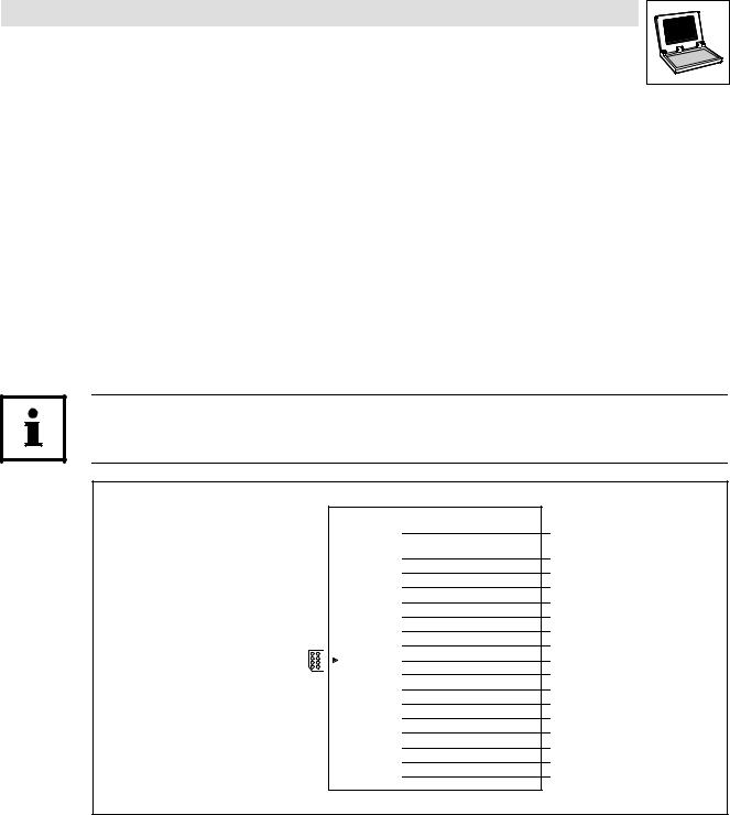
|
9300 Servo PLC |
|
System blocks |
2.4 |
AIF_IO_Management (node number 161) |
2.4AIF_IO_Management (node number 161)
2.4.1Inputs_AIF_Management
This SB monitors the communication of a communication module connected to the automation interface (AIF).
·In the event of an error, AIF_bCe0CommErr_b is set to TRUE and the communication error "CE0" (LECOM no. 61) is set. The response to this can be configured under C0126 (Lenze setting: off).
·New AIF communication modules (e.g. 2133 and 2175) also use
AIF_bFieldBusStateBit0_b ... AIF_bFieldBusStateBit15_b to transfer an error number from the communication module.
·C2121 displays the status.
Tip!
Please observe the documentation for the attached communication module.
|
|
|
|
Inputs_AIF_Management |
|
|
|
AIF |
AIF_bCe0CommErr_b |
|
|
|
Communication |
|
|
|
|
|
|
|
|
|
Error |
|
|
|
|
|
AIF_bFieldBusStateBit0_b |
|
|
|
|
|
|
|
|
|
AIF_bFieldBusStateBit1_b |
|
|
|
|
AIF_bFieldBusStateBit2_b |
|
|
|
|
AIF_bFieldBusStateBit3_b |
|
|
|
|
AIF_bFieldBusStateBit4_b |
|
|
|
|
AIF_bFieldBusStateBit5_b |
|
|
|
|
AIF_bFieldBusStateBit6_b |
|
|
AIF |
AIF_bFieldBusStateBit7_b |
|
Automation |
|
|
||
interface |
|
Fieldbus State |
AIF_bFieldBusStateBit8_b |
|
|
|
|
|
AIF_bFieldBusStateBit9_b |
|
|
|
|
AIF_bFieldBusStateBit10_b |
|
|
|
|
AIF_bFieldBusStateBit11_b |
|
|
|
|
AIF_bFieldBusStateBit12_b |
|
|
|
|
AIF_bFieldBusStateBit13_b |
|
|
|
|
AIF_bFieldBusStateBit14_b |
|
|
|
|
AIF_bFieldBusStateBit15_b |
|
|
|
|
|
Fig. 2−7 |
System block "Inputs_AIF_Management" |
L
9300 Servo PLC EN 5.1 |
2−23 |

2.4 |
9300 Servo PLC
System blocks
AIF_IO_Management (node number 161)
System variables
Variable |
Data type |
Signal type |
Address |
Display code |
Display |
Notes |
|
|
|
|
|
format |
|
|
|
|
|
|
|
|
AIF_bCe0CommErr_b |
|
|
%IX161.0.0 |
|
|
Communication error "CE0" |
|
|
|
|
|
|
|
AIF_bFieldBusStateBit0_b |
|
|
%IX161.1.0 |
|
|
Error number − bit 0 |
AIF_bFieldBusStateBit1_b |
|
|
%IX161.1.1 |
|
|
Error number − bit 1 |
|
|
|
|
|
|
|
AIF_bFieldBusStateBit2_b |
|
|
%IX161.1.2 |
|
|
Error number − bit 2 |
|
|
|
|
|
|
|
AIF_bFieldBusStateBit3_b |
|
|
%IX161.1.3 |
|
|
Error number − bit 3 |
AIF_bFieldBusStateBit4_b |
|
|
%IX161.1.4 |
|
|
Error number − bit 4 |
|
|
|
|
|
|
|
AIF_bFieldBusStateBit5_b |
|
|
%IX161.1.5 |
|
|
Error number − bit 5 |
AIF_bFieldBusStateBit6_b |
|
|
%IX161.1.6 |
|
|
Error number − bit 6 |
AIF_bFieldBusStateBit7_b |
Bool |
binary |
%IX161.1.7 |
|
|
Error number − bit 7 |
AIF_bFieldBusStateBit8_b |
|
|
%IX161.1.8 |
|
|
Error number − bit 8 |
AIF_bFieldBusStateBit9_b |
|
|
%IX161.1.9 |
|
|
Error number − bit 9 |
|
|
|
|
|
|
|
AIF_bFieldBusStateBit10_b |
|
|
%IX161.1.10 |
|
|
Error number − bit 10 |
|
|
|
|
|
|
|
AIF_bFieldBusStateBit11_b |
|
|
%IX161.1.11 |
|
|
Error number − bit 11 |
AIF_bFieldBusStateBit12_b |
|
|
%IX161.1.12 |
|
|
Error number − bit 12 |
|
|
|
|
|
|
|
AIF_bFieldBusStateBit13_b |
|
|
%IX161.1.13 |
|
|
Error number − bit 13 |
AIF_bFieldBusStateBit14_b |
|
|
%IX161.1.14 |
|
|
Error number − bit 14 |
AIF_bFieldBusStateBit15_b |
|
|
%IX161.1.15 |
|
|
Error number − bit 15 |
Codes
Code |
LCD |
Possible settings |
|
Info |
||
|
|
Lenze |
Selection |
|
|
|
|
|
|
|
|
|
|
C0126 |
MONIT CE0 |
3 |
|
|
|
Configuration for communication |
|
|
|
|
|
|
error "CE0" with automation |
|
|
|
|
|
|
interface |
|
|
|
0 |
TRIP |
|
|
|
|
|
2 |
Warning |
|
|
|
|
|
3 |
Off |
|
|
C2121 |
AIF: state |
G |
|
|
|
AIF−CAN: Status |
|
|
|
|
|
|
· Detailed information can be |
|
|
|
|
|
|
found in the documentation for |
|
|
|
|
|
|
the corresponding |
|
|
|
|
|
|
communication module. |
|
|
|
0 |
{dec} |
255 |
|
|
|
|
Decimal value is bit−coded: |
|
|
|
|
|
|
Bit 0 XCAN1_IN monitoring time |
|
|
|
|
|
|
Bit 1 XCAN2_IN monitoring time |
|
|
|
|
|
|
Bit 2 XCAN3_IN monitoring time |
|
|
|
|
|
|
Bit 3 |
XCAN bus−off |
|
|
|
|
|
Bit 4 |
XCAN operational |
|
|
|
|
|
Bit 5 |
XCAN pre−operational |
|
|
|
|
|
Bit 6 |
XCAN warning |
|
|
|
|
|
Bit 7 |
Internally assigned |
|
|
2−24 |
9300 Servo PLC EN 5.1 |
L |
Loading...