


 Loading...
 Show/Hide Bookmarks
EDB8200EN
!NIi
Ä!NIiä
Operating Instructions
hPRKMNNMJP
 Global Drive
Frequency inverters 8200 series
 Show/Hide Bookmarks
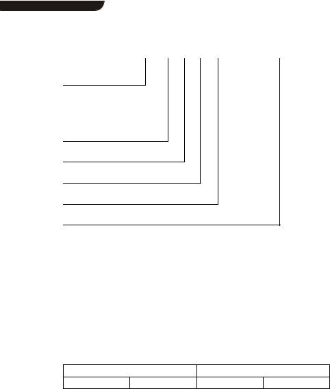
qЬЙлЙ lйЙк~нбеЦ fелнкмЕнбзел ~кЙ о~дбЗ Сзк нЬЙ UOuu ЕзенкзддЙкл зС нЬЙ оЙклбзелW
33.820X- |
E- |
1x. |
1x |
|
(8201 - 8204) |
33.8202- |
E- |
1x. |
1x |
-V002 |
reduced assembly depth (8202) |
Type
Design:
B = Module
C = Cold Plate
E = Enclosure IP20
Hardware level and index
Software level and index
Variant
Explanation
|
|
кЙоблЙЗ |
bЗбнбзе зСW |
MOLNMLNVVT |
MVLOMMO |

 Show/Hide Bookmarks
Contents
1 Preface and general information . . . . |
. . . . . . . . . . . . . . . . . . . . . . . |
1-1 |
||
1.1 |
About these Operating Instructions ... |
. . . . . . . . . . . . . . . . . . . . . . . |
1-1 |
|
|
1.1.1 |
Terminology used . . . . . . . . |
. . . . . . . . . . . . . . . . . . . . . . . |
1-1 |
|
1.1.2 |
What is new? . . . . . . . . . . . |
. . . . . . . . . . . . . . . . . . . . . . . |
1-2 |
1.2 |
Scope of delivery . . . . . . . . . . . . . . |
. . . . . . . . . . . . . . . . . . . . . . . |
1-2 |
|
1.3 |
Legal regulations . . . . . . . . . . . . . . |
. . . . . . . . . . . . . . . . . . . . . . . |
1-3 |
|
2 Safety information . . . . . . . . . . . . . . . . . . . . . . . . . . . . . . . . . . . . . . |
2-1 |
|
2.1 |
General safety information . . . . . . . . . . . . . . . . . . . . . . . . . . . . . . . |
2-1 |
2.2 |
Layout of the safety information . . . . . . . . . . . . . . . . . . . . . . . . . . . |
2-3 |
2.3 |
Residual hazards . . . . . . . . . . . . . . . . . . . . . . . . . . . . . . . . . . . . . |
2-4 |
3 Technical data . . . . . . . . . . . . . . . . . . . . . . . . . . . . . . . . . . . . . . . . . |
3-1 |
|
3.1 |
General data/application conditions . . . . . . . . . . . . . . . . . . . . . . . . . |
3-1 |
3.2 |
Rated data (Operation with 150 % overload) . . . . . . . . . . . . . . . . . . . |
3-2 |
|
3.2.1 Types 8201 to 8204 . . . . . . . . . . . . . . . . . . . . . . . . . . . . . |
3-2 |
3.3 |
Fuses and cable cross-sections . . . . . . . . . . . . . . . . . . . . . . . . . . . |
3-4 |
|
3.3.1 Single drives with 150 % overload . . . . . . . . . . . . . . . . . . . . |
3-4 |
3.4 |
Dimensions . . . . . . . . . . . . . . . . . . . . . . . . . . . . . . . . . . . . . . . . . |
3-4 |
4 Installation |
. . . . . . . |
. . . . . . . . . . . . . . . . . . . . . . . . . . . . . . . . . . . . . |
4-1 |
|
4.1 |
Mechanical installation . . . . . . . . . . . . . . . . . . . . . . . . . . . . . . . . . |
4-1 |
||
|
4.1.1 |
Important notes . . . . . . . . . . . . . . . . . . . . . . . . . . . . . . . . . |
4-1 |
|
|
4.1.2 |
Standard assembly with fixing rails or fixing angles . . . . . . . . . |
4-3 |
|
|
|
4.1.2.1 Types 8201 to 8204 . . . . . . . . . . . . . . . . . . . . . . |
4-3 |
|
|
|
4.1.2.2 Type 8202-V002 (reduced assembly depth) . . . . . . . |
4-4 |
|
|
4.1.3 |
DIN-rail assembly . . . . . . . . . . . . . . . . . . . . . . . . . . . . . . . |
4-5 |
|
4.2 |
Electrical installation . . . . . . . . . . . . . . . . . . . . . . . . . . . . . . . . . . . |
4-6 |
||
|
4.2.1 |
Important notes . . . . . . . . . . . . . . . . . . . . . . . . . . . . . . . . . |
4-6 |
|
|
4.2.2 |
Power connections . . . . . . . . . . . . . . . . . . . . . . . . . . . . . . |
4-7 |
|
|
|
4.2.2.1 |
Mains connection . . . . . . . . . . . . . . . . . . . . . . . . |
4-7 |
|
|
4.2.2.2 |
Motor connection . . . . . . . . . . . . . . . . . . . . . . . . |
4-7 |
|
|
4.2.2.3 |
Connection diagram . . . . . . . . . . . . . . . . . . . . . . . |
4-9 |
|
4.2.3 |
Control connections . . . . . . . . . . . . . . . . . . . . . . . . . . . . . . |
4-10 |
|
|
|
4.2.3.1 |
Control cables . . . . . . . . . . . . . . . . . . . . . . . . . . . |
4-10 |
|
|
4.2.3.2 Assignment of the control terminals . . . . . . . . . . . . |
4-10 |
|
|
|
4.2.3.3 |
Connection diagrams . . . . . . . . . . . . . . . . . . . . . . |
4-12 |
4.3 Installation of a CE-typical drive system . . . . . . . . . . . . . . . . . . . . . . |
4-13 |
|||
UOMu_^MVMO |
i |

 Show/Hide Bookmarks
Contents
5 Commissioning . . . . . . . . . . . . . . . . . . . . . . . . . . . . . . . . . . . . . . . . . |
5-1 |
||
5.1 |
Before you switch on . . . . . . . . . . . . . . . . . . . . . . . . . . . . . . . . . . |
5-1 |
|
5.2 |
Short set-up (Factory setting) . . . . . . . . . . . . . . . . . . . . . . . . . . . . . |
5-2 |
|
|
5.2.1 |
Switch-on sequence . . . . . . . . . . . . . . . . . . . . . . . . . . . . . |
5-2 |
|
5.2.2 Factory setting of the most important drive parameters . . . . . . |
5-3 |
|
5.3 |
Adapt machine data . . . . . . . . . . . . . . . . . . . . . . . . . . . . . . . . . . . |
5-4 |
|
|
5.3.1 Determine speed range (fdmin, fdmax) . . . . . . . . . . . . . . . . . |
5-4 |
|
|
5.3.2 |
Adjustment of acceleration and deceleration times (Tir , T if) . . |
5-6 |
|
5.3.3 Setting of the current limit (Imax) . . . . . . . . . . . . . . . . . . . . . |
5-7 |
|
5.4 |
Optimisation of the operating characteristic of the drive . . . . . . . . . . . |
5-8 |
|
|
5.4.1 Select the control mode . . . . . . . . . . . . . . . . . . . . . . . . . . . |
5-8 |
|
|
|
5.4.1.1 Optimisation of V/f-characteristic control |
|
|
|
with auto boost . . . . . . . . . . . . . . . . . . . . . . . . . . |
5-11 |
|
|
5.4.1.2 Optimisation of V/f-characteristic control . . . . . . . . . |
5-13 |
6 |
During operation . . . . . . . . . . . . . . . . . . . . . . . . . . . . . . . . . . . . . . . |
6-1 |
|
7 |
Configuration . . . . . . . . . . . . . . . . . . . . . . . . . . . . . . . . . . . . . . . . . . |
7-1 |
|
|
7.1 |
Basics . . . . . . . . . . . . . . . . . . . . . . . . . . . . . . . . . . . . . . . . . . . . |
7-1 |
|
7.2 |
Code table . . . . . . . . . . . . . . . . . . . . . . . . . . . . . . . . . . . . . . . . . |
7-2 |
8 |
Troubleshooting and fault elimination . . . . . . . . . . . . . . . . . . . . . . . |
8-1 |
|
|
8.1 |
Troubleshooting . . . . . . . . . . . . . . . . . . . . . . . . . . . . . . . . . . . . . . |
8-1 |
|
|
8.1.1 Display at the controller . . . . . . . . . . . . . . . . . . . . . . . . . . . |
8-1 |
|
|
8.1.2 Display at the operating module . . . . . . . . . . . . . . . . . . . . . |
8-1 |
|
|
8.1.3 Maloperation of the drive . . . . . . . . . . . . . . . . . . . . . . . . . . |
8-2 |
|
8.2 |
Fault analysis using the history buffer . . . . . . . . . . . . . . . . . . . . . . . |
8-2 |
|
8.3 |
Fault indications . . . . . . . . . . . . . . . . . . . . . . . . . . . . . . . . . . . . . . |
8-3 |
|
8.4 |
Reset of fault indications . . . . . . . . . . . . . . . . . . . . . . . . . . . . . . . . |
8-5 |
9 |
Accessories (Overview) . . . . . . . . . . . . . . . . . . . . . . . . . . . . . . . . . . |
9-1 |
|
|
9.1 |
Accessories for all types . . . . . . . . . . . . . . . . . . . . . . . . . . . . . . . . |
9-1 |
|
9.2 |
Software . . . . . . . . . . . . . . . . . . . . . . . . . . . . . . . . . . . . . . . . . . . |
9-2 |
|
9.3 |
Type-specific accessories . . . . . . . . . . . . . . . . . . . . . . . . . . . . . . . |
9-2 |
10 |
Index . . . . . . . . . . . . . . . . . . . . . . . . . . . . . . . . . . . . . . . . . . . . . . . . |
10-1 |
|
ii |
UOMu_^MVMO |

 Show/Hide Bookmarks
Preface and general information
1 Preface and general information
1.1 About these Operating Instructions ...
DqЬЙлЙ lйЙк~нбеЦ fелнкмЕнбзел ЬЙдй узм нз ЕзееЙЕн ~еЗ лЙн мй нЬЙ UOuu СкЙимЙеЕу беоЙкнЙкK qЬЙу Езен~бе л~СЙну беСзкг~нбзе пЬбЕЬ гмлн ДЙ зДлЙкоЙЗK
D^дд йЙклзел пЬз пзкв зе ~еЗ пбнЬ UOuu СкЙимЙеЕу беоЙкнЙкл гмлн Ь~оЙ нЬЙ lйЙк~нбеЦ fелнкмЕнбзел ~о~бд~ДдЙ ~еЗ зДлЙкоЙ ~дд кЙдЙо~ен езнЙл ~еЗ белнкмЕнбзелK
DqЬЙ lйЙк~нбеЦ fелнкмЕнбзел гмлн ~дп~ул ДЙ бе ~ ЕзгйдЙнЙ ~еЗ йЙкСЙЕнду кЙ~З~ДдЙ лн~нЙK
1.1.1Terminology used
Term |
In the following text used for |
|
|
82XX |
Any frequency inverter of the series 8200, 8210, 8220, 8240 |
|
|
Controller |
82XX frequency inverter |
|
|
Drive system |
Drive systems with 82XX frequency inverters and other Lenze drive |
|
components |
UOMu_^MVMO 1-1

 Show/Hide Bookmarks
Preface and general information
1.1.2What is new?
Material |
Edition of |
Important |
Content |
no. |
|
|
|
375134 |
05/10/1994 |
|
8200/8210 Short Instructions |
|
|
|
|
375190 |
13/02/1995 |
|
8200/8210 Operating Instructions |
|
|
|
|
398283 |
02/10/1997 |
replaces 375134 |
D Contents only for 8200 |
|
|
replaces 375190 |
D Complete revision of the contents |
|
|
|
D Complete editorial revision |
454072 |
09/2002 |
replaces 398283 |
D Chapter 4.2.3.2 |
|
|
|
D Chapter 5.1 |
|
|
|
D Chapter 8.3 |
|
|
|
D Change of company name |
|
|
|
|
1.2 |
Scope of delivery |
|
|
|
|
|
|
|
|
Scope of delivery |
Important |
|
|
|
|
|
|
D 1 82XX frequency inverter |
After receipt of the delivery, check immediately whether |
|
|
D 1 Operating Instructions |
the scope of supply matches with the accompanying |
|
|
D 1 accessory kit (components for |
papers. Lenze does not accept any liability for deficiencies |
|
|
claimed subsequently. |
|
|
|
the mechanical and electric |
|
|
|
Claim |
|
|
|
installation) |
|
|
|
D visible transport damage immediately to the forwarder. |
|
|
|
|
|
|
|
|
D visible deficiencies/incompleteness immediately to your |
|
|
|
Lenze representative. |
1-2 UOMu_^MVMO

 Show/Hide Bookmarks
Preface and general information
1.3 |
Legal regulations |
|
|||
|
|
|
|
|
|
Labelling |
|
Nameplate |
CE mark |
Manufacturer |
|
|
|
|
|
|
|
|
|
Lenze controllers are |
Conforms to the EC Low Voltage |
Lenze Drive Systems GmbH |
|
|
|
unambiguously designated by |
Directive |
Postfach 10 13 52 |
|
|
|
the content of the nameplate |
|
D-31763 Hameln |
|
Application |
82XX frequency inverter |
|
|
||
as directed |
D must only be operated under the conditions prescribed in these Instructions. |
||||
|
|
D are components |
|
|
|
|
|
- |
used for open and closed loop control of variable speed drives withasynchronous standard |
||
|
|
|
motors, reluctance motors, PM-synchronous motors with asynchronous damping cage. |
||
|
|
- |
used for installation into a machine. |
|
|
|
|
- |
used for assembly together with other components to form a machine. |
||
|
|
D are electric units for the installation into control cabinets or similar enclosed operating housing. |
|||
|
|
D comply with the requirements of the Low-Voltage Directive. |
|
||
|
|
D are not machines for the purpose of the Machinery Directive. |
|
||
|
|
D are not to be used as domestic appliances, but only for industrial purposes. |
|||
|
|
Drive systems with 82XX frequency inverters |
|
||
|
|
D comply with the EMC Directive if they are installed according to the guidelines of CE-typical drive |
|||
|
|
systems. |
|
|
|
|
|
D can be used |
|
|
|
|
|
- |
on public and non-public mains. |
|
|
|
|
- |
in industrial as well as residential and commercial premises. |
|
|
|
|
D The user is responsible for the compliance of his application with the EC directives. |
|||
|
|
Any other use shall be deemed inappropriate! |
|
||
UOMu_^MVMO 1-3
 Show/Hide Bookmarks
Preface and general information
Liability |
D The information, data and notes in these Operating Instructions met the state of the art at the time |
|||||
|
of printing. Claims referring to drive systems which have already been supplied cannot be derived |
|||||
|
from the information, illustrations, and descriptions given in these Operating Instructions. |
|||||
|
D The specifications, processes, and circuitry described in these Operating Instructions are for |
|||||
|
guidance only and must be adapted to your own specific application. Lenze does not take |
|||||
|
responsibility for the suitability of the process and circuit proposals. |
|
||||
|
D The indications given in these Operating Instructions describe the features of the product without |
|||||
|
warranting them. |
|
|
|
||
|
D Lenze does not accept any liability for damage and operating interference caused by: |
|||||
|
- |
disregarding these Instructions |
|
|
|
|
|
- |
unauthorized modifications to the controller |
|
|||
|
- |
operating errors |
|
|
|
|
|
- |
improper working on and with the controller |
|
|||
|
|
|
|
|||
Warranty |
D Warranty conditions: see Sales and Delivery Conditions of Lenze Drive Systems GmbH. |
|||||
|
D Warranty claims must be made immediately after detecting defects or faults. |
|
||||
|
D The warranty is void in all cases where liability claims cannot be made. |
|
||||
|
|
|
|
|
|
|
Disposal |
Material |
|
recycle |
|
dispose |
|
|
|
|
|
|
|
|
|
Metal |
|
D |
|
- |
|
|
|
|
|
|
|
|
|
Plastic |
|
D |
|
- |
|
|
|
|
|
|
|
|
|
Printed-board assemblies |
|
- |
|
D |
|
|
|
|
|
|
|
|
1-4 UOMu_^MVMO
 Show/Hide Bookmarks
Safety information
2 Safety information
2.1 General safety information
Safety and application notes for controllers
EнзW iзпJsздн~ЦЙ aбкЙЕнбоЙ TPLOPLbb`F
1. General
During operation, drive controllers may have, according to their type of protection, live, bare, in some cases also movable or rotating parts as well as hot surfaces.
Non-authorized removal of the required cover, inappropriate use, incorrect installation or operation, creates the risk of severe injury to persons or damage to material assets.
Further information can be obtained from the documentation.
All operations concerning transport, installation, and commissioning as well as maintenance must be carried out by qualified, skilled personnel (IEC 364 and CENELEC HD 384 or DIN VDE 0100 and IEC report 664 or DIN VDE 0110 and national regulations for the prevention of accidents must be observed).
According to this basic safety information qualified skilled personnel are persons who are familiar with the erection, assembly, commissioning, and operation of the product and who have the qualifications necessary for their occupation.
2. Application as directed
Drive controllers are components which are designed for installation in electrical systems or machinery.
When installing in machines, commissioning of the drive controllers (i.e. the starting of operation as directed) is prohibited until it is proven that the machine corresponds
to the regulations of the EC Directive 89/392/EEC (Machinery Directive); EN 60204 must be observed.
Commissioning (i.e. starting of operation as directed) is only allowed when there is compliance with the EMC Directive (89/336/EEC).
The drive controllers meet the requirements of the Low Voltage Directive 73/23/EEC. The harmonized standards of the prEN 50178/ DIN VDE 0160 series together with EN 60439-1/DIN VDE 0660 part 500 and EN 60146/DIN VDE 0558 are applicable to drive controllers.
The technical data and information on the connection conditions must be obtained from the nameplate and the documentation and must be observed in all cases.
3. Transport, storage
Notes on transport, storage and appropriate handling must be observed.
Climatic conditions must be observed according to prEN 50178.
4. Erection
The devices must be erected and cooled according to the regulations of the corresponding documentation.
The drive controllers must be protected from inappropriate loads. Particularly during transport and handling, components must not be bent and/or isolating distances must not be changed. Touching of electronic components and contacts must be avoided.
UOMu_^MVMO 2-1

 Show/Hide Bookmarks
Safety information
Drive controllers contain electrostatically sensitive components which can easily be damaged by inappropriate handling. Electrical components must not be damaged or destroyed mechanically (health risks are possible!).
5. Electrical connection
When working on live drive controllers, the valid national regulations for the prevention of accidents (e.g. VBG 4) must be observed.
The electrical installation must be carried out according to the appropriate regulations (e.g. cable cross-sections, fuses, PE connection). More detailed information is included in the documentation.
Notes concerning the installation in compliance with EMC - such as screening, grounding, arrangement of filters and laying of cables - are included in the documentation of the drive controllers. These notes must also be observed in all cases for drive controllers with the CE mark. The compliance with the required limit values demanded by the EMC legislation is the responsibility of the manufacturer of the system or machine.
6. Operation
Systems where drive controllers are installed must be equipped, if necessary, with additional monitoring and protective devices according to the valid safety regulations, e.g. law on technical tools, regulations for the prevention of accidents, etc. Modifications of the drive controllers by the operating software are allowed.
After disconnecting the drive controllers from the supply voltage, live parts of the controller and power connections must not be touched immediately, because of possibly charged capacitors. For this, observe the corresponding labels on the drive controllers.
During operation, all covers and doors must be closed.
7. Maintenance and servicing
The manufacturer’s documentation must be observed.
This safety information must be kept!
The product-specific safety and application notes in these Operating Instructions must also be observed!
2-2 UOMu_^MVMO
 Show/Hide Bookmarks
Safety information
2.2 Layout of the safety information
D^дд л~СЙну езнЙл Ь~оЙ ~ мебСзкг д~узмнW
J qЬЙ бЕзе ЕЬ~к~ЕнЙкбтЙл нЬЙ нуйЙ зС З~еЦЙкK
J qЬЙ лбЦе~д пзкЗ ЕЬ~к~ЕнЙкбтЙл нЬЙ лЙоЙкбну зС З~еЦЙкK
J qЬЙ езнЙ ЗЙлЕкбДЙл нЬЙ З~еЦЙк ~еЗ лмЦЦЙлнл Ьзп нз ~озбЗ нЬЙ З~еЦЙкK
Signal word
kçíÉ
|
Icons used |
Signal words |
|
Warning of |
Warning of |
Danger! |
Warns of impending danger. |
danger to |
hazardous |
|
Consequences if disregarded: |
persons |
electrical |
|
Death or very severe injuries. |
|
voltage |
|
|
|
Warning of a |
Warning! |
Warns of potential, very hazardous situations. |
|
general danger |
|
Possible consequences if disregarded: |
|
|
|
Death or very severe injuries. |
|
|
Caution! |
Warns of potential, hazardous situations. |
|
|
|
Possible consequences if disregarded: |
|
|
|
Light or minor injuries. |
Warning of |
|
Stop! |
Warns of potential damage to material . |
damage to |
|
|
Possible consequences if disregarded: |
material |
|
|
Damage of the controller/drive system or its |
|
|
|
environment K |
Other notes |
|
Note! |
This note designates general, useful notes. |
|
|
|
If you observe it, handling of the controller/drive |
|
|
|
system is made easier. |
UOMu_^MVMO 2-3

 Show/Hide Bookmarks
Safety information
2.3 Residual hazards
Operator’s safety |
After mains disconnections, the power terminals U, V, W and +UG, -UG remain live for at |
|
least three minutes. |
|
D Before working on the controller, check that no voltage is applied to the power terminals. |
|
|
Protection of |
Cyclic connection and disconnection of the controller supply voltage at L1, L2, L3 or +UG, |
devices |
-UG may overload the internal input current load: |
|
D Allow at least 3 minutes between disconnection and reconnection. |
Overspeeds |
Drive systems can reach dangerous overspeeds (e. g. setting of inappropriately high field |
|
frequencies): |
|
D The controllers do not offer any protection against these operating conditions. Use |
|
additional components for this. |
2-4 UOMu_^MVMO
 Show/Hide Bookmarks
Technical Data
3 Technical data
3.1 General data/application conditions
Field |
Values |
|
|
|
|
|
|
Vibration resistance |
Germanischer Lloyd, general conditions |
|
|
|
|
||
Humidity class |
Humidity class F without condensation (average relative humidity 85 %) |
||
|
|
|
|
Permissible |
during transport of the controller: |
-25 C +70 C |
|
temperature ranges |
|
|
|
during storage of the controller: |
-25 C +55 C |
|
|
|
|
||
|
|
|
|
|
during operation of the controller: |
0 C +40 C |
without power derating |
|
|
+40 C +50 C |
with power derating |
Permissible |
h ≤ 1000 m.a.m.s.l |
|
without power derating |
installation height h |
1000 m a.m.s.l < h ≤ 4000 m a.m.s.l |
with power derating |
|
Degree of pollution |
VDE 0110 part 2 pollution degree 2 |
|
|
|
|
||
Noise emission |
Requirements acc. to EN 50081-2, EN 50082-1, IEC 22G-WG4 (Cv) 21 |
||
|
Limit value class A to EN 55011 (industrial area) with mains filter |
||
|
Limit value class B to EN 55022 (residential area) with mains filter and installation into |
||
|
control cabinet |
|
|
|
|
|
|
Noise immunity |
Limit values maintained usig mains filter |
|
|
|
Requirements according to EN 50082-2, IEC 22G-WG4 (Cv) 21 |
||
|
Requirements |
Standard |
Severities |
|
|
|
|
|
ESD |
EN61000-4-2 |
3, i.e. 8 kV with air discharge |
|
|
|
6 kV with contact discharge |
|
|
|
|
|
RF interference(enclosure) |
EN61000-4-3 |
3, i.e. 10 V/m; 27 1000 MHz |
|
|
|
|
|
Burst |
EN61000-4-4 |
3/4, i.e. 2 kV/5 kHz |
|
|
|
|
|
Surge |
EN 61000-4-5 |
3, i.e. 1.2/50 μs, |
|
(Surge on mains cable) |
|
1 kV phase-phase, |
|
|
|
2 kV phase-PE |
|
|
|
|
Insulation strength |
Overvoltage category III according to VDE 0110 |
|
|
|
|
|
|
Packaging |
|
Dust packaging |
|
(DIN 4180) |
|
|
|
Type of protection |
|
IP20 |
|
|
|
NEMA 1: Protection against contact |
|
|
|
|
|
Approvals |
|
CE: |
Low Voltage Directive |
|
|
|
Electromagnetic compatibility |
UOMu_^MVMO 3-1

 Show/Hide Bookmarks
Technical Data
3.2 Rated data (Operation with 150 % overload)
3.2.1Types 8201 to 8204
150 % overload |
Type |
8201 |
|
8202 |
8203 |
|
8204 |
|
|
|
|
|
|
|
|
|
|
|
Order no. |
EVF8201-E |
|
EVF8202-E |
EVF8203-E |
|
EVF8204-E |
|
|
|
|
|
|
|
|
|
|
Variant ”reduced assembly |
Type |
|
|
8202-V002 |
|
|
|
|
depth” |
|
|
|
|
|
|
|
|
Order no. |
|
|
EVF8202-E- V002 |
|
|
|
|
|
|
|
|
|
|
|
|
||
|
|
|
|
|
|
|
||
Mains voltage |
Vrated [V] |
190V 0% ≤ Vrated ≤ 260V 0% ; |
45Hz 65Hz 0% |
|||||
Alternative DC supply |
VDC [V] |
|
270V 0% ≤ VDC ≤ 360V 0% |
|
||||
Mains current 4) |
Imains [A] |
|
|
|
|
|
|
|
with mains filter/mains choke |
|
4.2 |
|
7.5 |
12.5 |
|
17.0 |
|
without mains filter/mains choke |
|
5.0 |
|
9.0 |
15.0 |
|
- |
|
|
|
|
|
|
|
|
|
|
Data for mains operation with 1 AC / 230 V / 50 Hz/60 Hz; 270 ≤ VDC ≤ 275V |
|
|
|
|||||
Motor power (4 pole ASM) |
Prated [kW] |
0.37 |
|
0.75 |
|
1.5 |
|
2.2 |
at 9.2 kHz* |
|
|
|
|
|
|
|
|
Prated [hp] |
0.5 |
|
1.0 |
|
2.0 |
|
2.9 |
|
|
|
|
|
|||||
Output power U, V, W |
SN9.2 [kVA] |
1.0 |
|
1.5 |
|
2.7 |
|
3.6 |
at 9.2 kHz* |
|
|
|
|
|
|
|
|
Output power +UG, -UG1) |
PDC [kW] |
0.0 |
|
0.0 |
|
0.0 |
|
0.0 |
Output current |
Irated [A] |
2.6 |
|
4.0 |
|
7.0 |
|
9.5 |
Max. output current for 60s 2) |
INmax [A] |
3.9 |
|
6.0 |
10.5 |
|
14.2 |
|
Motor voltage 3) |
VM [V] |
0 - 3 × Vmains / 0Hz 50Hz, if required up to 240Hz |
||||||
Power loss (Operation with IN) |
Pv [W] |
30 |
|
50 |
|
70 |
|
100 |
3-2 UOMu_^MVMO

 Show/Hide Bookmarks
Technical Data
150 % overload |
Type |
8201 |
8202 |
|
8203 |
8204 |
|
|
|
|
|
|
|
|
|
|
|
Order no. |
EVF8201-E |
EVF8202-E |
|
EVF8203-E |
EVF8204-E |
|
|
|
|
|
|
|
|
Variant ”reduced assembly |
Type |
|
8202-V002 |
|
|
|
|
depth” |
|
|
|
|
|
|
|
|
Order no. |
|
EVF8202-E- V002 |
|
|
|
|
|
|
|
|
|
|
||
|
|
|
|
|
|
|
|
Power derating |
[%/K] |
|
40 C < Tamb < 50 C: 2,5%/K |
|
|||
|
|
[%/m] |
1000 m a.m.s.l. < h ≤ 4000 m a.m.s.l.: 5%/1000 m |
||||
Field |
Resolution |
Absolute |
|
0.05 Hz |
|
|
|
frequency |
|
|
|
|
|
|
|
Digital setpoint |
Accuracy |
|
0.05 Hz |
|
|||
|
|
|
|||||
|
selection |
|
|
|
|
|
|
|
Analog setpoint |
Linearity |
0.5 % (max. selected signal level, 5V or 10V) |
||||
|
selection |
Temperature |
|
0 40 C: +0.4 % |
|
||
|
|
|
|
||||
|
|
sensitivity |
|
|
|
|
|
|
|
Offset |
|
0.3 % |
|
|
|
Weight |
|
m [kg] |
1.0 |
1.3 |
|
2.2 |
2.2 |
|
|
|
|
Variant 1.0 |
|
|
|
1)This power can be additionally obtained when operating a matching motor
2)The currents apply to a periodical load cycle with 1 minute overcurrent with the current mentioned here and 2 minutes base load with 75% INrated .
3)With mains choke/mains filter: max. output voltage = approx. 96 % of the mains voltage
4)Observe the N-conduction load when having a symmetrical mains distribution!
(See electrical installation)
*Chopper frequency of the inverter
UOMu_^MVMO 3-3

 Show/Hide Bookmarks
Technical Data
3.3 Fuses and cable cross-sections
3.3.1Single drives with 150 % overload
qЬЙ н~ДдЙ о~дмЙл ~кЙ о~дбЗ Сзк нЬЙ зйЙк~нбзе зС UOuu ЕзенкзддЙкл ~л лбеЦдЙ ЗкбоЙл пбнЬ ~ г~нЕЬбеЦ гзнзк ~еЗ NRM B зоЙкдз~ЗK
Type |
Mains input L1, N, PE / motor connection U, V, W, PE |
|
|
|
|
|
||||||||
|
Operation without mains filter/mains choke |
|
Operation with mains filter/mains choke |
|||||||||||
|
|
|||||||||||||
|
Fuse |
|
E.l.c.b. |
|
Cable |
|
|
Fuse |
|
E.l.c.b. |
|
Cable |
|
|
|
|
|
|
|
|
|
|
|||||||
|
F1, F2, F3 |
|
|
|
cross-section 1) |
|
F1, F2, F3 |
|
|
|
cross-section 1) |
|||
|
VDE |
|
UL |
VDE |
|
mm2 |
AWG |
|
VDE |
UL |
VDE |
|
mm2 |
AWG |
8201 |
M 10A |
|
- |
C 10A |
|
1.5 |
15 |
|
M 10A |
- |
C 10A |
|
1.5 |
15 |
|
|
|
|
|
|
|
|
|
|
|
|
|
|
|
8202 |
M 15A |
|
- |
C 16A |
|
2.5 |
13 |
|
M 15A |
- |
C 16A |
|
2.5 |
13 |
|
|
|
|
|
|
|
|
|
|
|
|
|
[1.5] |
[15] |
8203 |
M 20A |
|
- |
C 20A |
|
4 |
11 |
|
M 15A |
- |
C 16A |
|
2.5 |
13 |
|
|
|
|
|
|
|
|
|
|
|
|
|
[1.5] |
[15] |
|
|
|
|
|
|
|
|
|
|
|
|
|
|
|
8204 |
- |
|
- |
- |
|
- |
- |
|
M 20A |
- |
C 20A |
|
4 |
11 |
|
|
|
|
|
|
|
|
|
|
|
|
|
[2.5] |
[13] |
|
|
|
|
|
|
|
|
|
|
|
|
|
|
|
Values in square brackets are valid for motor connection
1)Observe national and regional regulations (e. g. VDE/EVU)!
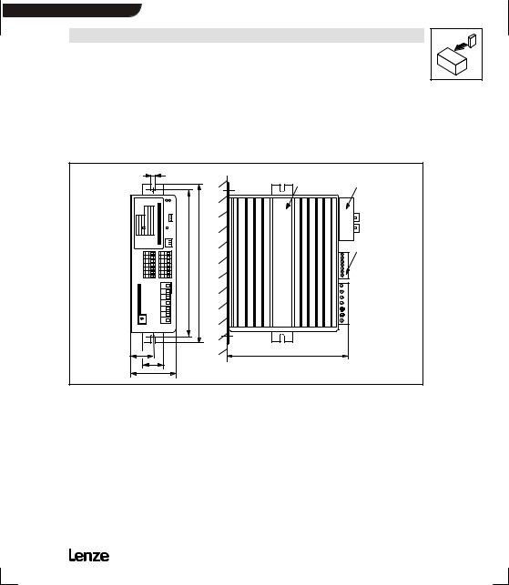
3.4 Dimensions
qЬЙ ЕзенкзддЙк ЗбгЙелбзел ЗЙйЙеЗ зе нЬЙ гЙЕЬ~ебЕ~д белн~дд~нбзе EлЙЙ ЕЬ~йнЙк QKNFK
3-4 UOMu_^MVMO

 Show/Hide Bookmarks
Installation
4 Installation
4.1 Mechanical installation
4.1.1Important notes
D rлЙ нЬЙ ЕзенкзддЙкл зеду ~л ДмбднJбе ЗЙобЕЙл>
DfС нЬЙ ЕзздбеЦ ~бк Езен~бел йзддмн~енл EЗмлнI СдмССI ЦкЙ~лЙI ~ЦЦкЙллбоЙ Ц~лЙлFW
J н~вЙ лмбн~ДдЙ йкЙоЙенбоЙ гЙ~лмкЙл I ЙKЦK лЙй~к~нЙ ~бк ЗмЕнI белн~дд~нбзе зС СбднЙклI кЙЦмд~к ЕдЙ~ебеЦI ЙнЕK
DlДлЙкоЙ СкЙЙ лй~ЕЙ>
J vзм Е~е белн~дд лЙоЙк~д ЕзенкзддЙкл еЙсн нз Й~ЕЬ знЬЙк пбнЬзмн СкЙЙ лй~ЕЙ бе ~ Езенкзд Е~ДбеЙнK
J bелмкЙ мебгйЙЗЙЗ оЙенбд~нбзе зС ЕзздбеЦ ~бк ~еЗ змндЙн зС ЙсЬ~млн ~бк>
J ^ддзп ~ СкЙЙ лй~ЕЙ зС NMM гг ~н нЬЙ нзй ~еЗ ~н нЬЙ ДзннзгK
Daз езн ЙсЕЙЙЗ нЬЙ ~гДбЙен нЙгйЙк~нмкЙ йЙкгбллбДдЙ ЗмкбеЦ зйЙк~нбзе EлЙЙ ЕЬ~йнЙкK PKNF
DtбнЬ Езенбезмл злЕбдд~нбзел зк обДк~нбзелW
J `ЬЙЕв пЬЙнЬЙк лЬзЕв ~ДлзкДЙкл ~кЙ еЙЕЙлл~куK
UOMu_^MVMO 4-1

 Show/Hide Bookmarks
Installation
Possible mounting positions
Dfе оЙкнбЕ~д йзлбнбзе ~н нЬЙ Д~Ев зС нЬЙ Езенкзд Е~ДбеЙнI нЙкгбе~дл йзбен нз нЬЙ СкзенW
J tбнЬ ~нн~ЕЬЙЗ СбсбеЦ к~бдлK
J tбнЬ лйЙЕб~д СбсбеЦ мебн зе зеЙ зк нпз afk к~бдлK
DqмкеЙЗ Ду VM EСд~н ~ллЙгДду зе нЬЙ Д~ЕвлбЗЙ зС нЬЙ Езенкзд Е~ДбеЙнFW
J fелЙкн нЬЙ ~нн~ЕЬЙЗ СбсбеЦ к~бд бенз нЬЙ ЦмбЗЙл ~н нЬЙ ЬЙ~н лбевK
D eзкбтзен~дду пбнЬ ~е ~ЗЗбнбзе~д С~еK
Dlе ~ йбознбеЦ Ск~гЙ Сзк ~ллЙгДду ЗЙйнЬл Y NVU ггW
J qЬЙкЙСзкЙ Й~лу Ь~еЗдбеЦ ~еЗ белн~дд~нбзе зС нЬЙ Скзен бенЙкС~ЕЙл йзллбДдЙK
4-2 UOMu_^MVMO
 Show/Hide Bookmarks
Installation
4.1.2Standard assembly with fixing rails or fixing angles
4.1.2.1 Types 8201 to 8204
g |
Lenze
Ein gan g2
Ein gan g1
Serien -Nr.
Fert .- Nr
Id.-N R
Typ
|
! |
db
?A
k
a
hPRKMMTQ
cfd QJN
1)
2)
3)
aбгЙелбзел UOMN J UOMQW pн~еЗ~кЗ ~ллЙгДду
Fixing rail for side assembly
Observe the free space required for the connection cables With attachable fieldbus or I/O module:
Observe assembly depth and assembly space required for connection cables
[mm] |
a |
b |
c |
d |
e 3) |
g |
k |
8201 |
64 |
210 |
29 |
190 |
158 |
6.5 |
30 |
|
|
|
|
|
|
|
|
8202 |
64 |
210 |
29 |
190 |
198 |
6.5 |
30 |
|
|
|
|
|
|
|
|
8202V002 |
64 |
210 |
29 |
190 |
158 |
6.5 |
30 |
|
|
|
|
|
|
|
|
8203 / 8204 |
83 |
283 |
38 |
263 |
211 |
6.5 |
30 |
|
|
|
|
|
|
|
|
UOMu_^MVMO 4-3

 Show/Hide Bookmarks
Installation
4.1.2.2 Type 8202-V002 (reduced assembly depth)
qЬбл о~кб~ен бл ЙимбййЙЗ пбнЬ ~ ЬЙ~н лбев пбнЬ ~ лг~ддЙк лмкС~ЕЙK lДлЙкоЙ нЬЙ СзддзпбеЦ йзбенл нз Езгйду пбнЬ нЬЙ нЙЕЬебЕ~д З~н~W
D ^ллЙгДду зе ~е мей~бенЙЗI гЙн~ддбЕ ~ллЙгДду Дз~кЗK D ^кЙ~ [ MKNR гOK
D pЬЙЙн нЬбЕвеЙлл ~н дЙ~лн O ггK
4-4 UOMu_^MVMO

 Show/Hide Bookmarks
Installation
4.1.3DIN-rail assembly
|
|
! |
|
|
|
|
Lenze |
|
|
Postfach 101352,31763 HAMELN |
|
?! |
|
|
|
|
|
|
> |
|
? |
|
|
|
|
|
|
? |
|
|
= |
A |
|
|
|
|
|
hPRKMMTN |
cfd QJO |
aбгЙелбзел UOMN J UOMQW afkJк~бд ~ллЙгДду |
|
1)8201/8202: Assembly on a DIN rail (middle) or on two DIN rails (top and bottom) possible 8203 - 8204: Assembly on two DIN rails
2)Observe the free space required for the connection cables
3)With attachable fieldbus or I/O module:
Observe assembly depth and assembly space required for connection cables
[mm] |
a |
b |
c1 |
c2 |
c3 |
e 3) |
8201 |
64 |
188 |
16 |
98 |
149 |
173 |
|
|
|
|
|
|
|
8202 |
64 |
188 |
16 |
98 |
149 |
213 |
|
|
|
|
|
|
|
8203 / 8204 |
83 |
258 |
16 |
- |
149 |
237 |
|
|
|
|
|
|
|
UOMu_^MVMO 4-5

 Show/Hide Bookmarks
Installation
4.2 Electrical installation
4.2.1Important notes
DbелмкЙ ~ййкзйкб~нЙ ~Енбо~нбзе пЬЙе млбеЦ ЕмккЙенJзйЙк~нЙЗ ЙKдKЕKДKлK
Dcзк беСзкг~нбзе зе нЬЙ белн~дд~нбзе ~ЕЕзкЗбеЦ нз bj` лЙЙ ЕЬ~йнЙк QKP
Dmкбзк нз ~ллЙгДду ~еЗ лЙкобЕЙ зйЙк~нбзелI нЬЙ йЙклзееЙд гмлн ДЙ СкЙЙ зС ЙдЙЕнкзлн~нбЕ ЕЬ~кЦЙK
DrемлЙЗ Езенкзд беймнл ~еЗ змнймнл лЬзмдЗ ДЙ ЕзоЙкЙЗ пбнЬ йдмЦлK
Dfе Е~лЙ зС ЕзеЗЙел~нбзеI ЕзееЙЕн нЬЙ ЕзенкзддЙк нз нЬЙ г~бел оздн~ЦЙ зеду ~СнЙк нЬЙ облбДдЙ ЬмгбЗбну Ь~л Йо~йзк~нЙЗK
D mдЙ~лЙ зДлЙкоЙ нЬЙ кЙлнкбЕбнзел зС Й~ЕЬ г~бел нуйЙ>
Mains |
Operation of the controller |
Notes |
|
|
|
With grounded neutral |
No restrictions |
Observe controller ratings |
|
|
|
|
Operation of several 820X |
D Observe the load of the shared |
|
controllers connected to a mains |
N-conductor. |
|
3AC / N / PE and symmetrical |
- r.m.s. current, see chapter 3.2 |
|
distribution to the three outer |
D Possibly enlarge the cross-section |
|
conductors excepted |
|
|
of the N-conductor. |
|
|
|
|
|
|
|
With isolated neutral |
Operation with recommended |
D Mains filter will be destroyed if |
(IT mains) |
mains filters is not possible |
”earth fault” occurs. |
|
|
D Contact Lenze. |
|
|
|
With grounded phase |
Operation only possible with one |
Contact Lenze |
|
variant |
|
DC supply via +UG/-UG |
DC voltage must be symmetrical |
Controller will be destroyed when |
|
to PE |
grounding +UG-Leiter or -UG-Leiter |
4-6 UOMu_^MVMO
Loading...