


 Loading...
ThinkSystem SR250
Maintenance Manual
Machine Types: 7Y51, 7Y52, 7Y72 and 7Y73
Note
Before using this information and the product it supports, be sure to read and understand the safety information and the safety instructions, which are available at: http://thinksystem.lenovofiles.com/help/topic/safety_documentation/pdf_files.html
In addition, be sure that you are familiar with the terms and conditions of the Lenovo warranty for your server, which can be found at:
http://datacentersupport.lenovo.com/warrantylookup
First Edition (November 2018)
© Copyright Lenovo 2018.
LIMITED AND RESTRICTED RIGHTS NOTICE: If data or software is delivered pursuant to a General Services Administration (GSA) contract, use, reproduction, or disclosure is subject to restrictions set forth in Contract No. GS-35F- 05925.

Contents
Safety . . . . . . . |
. . . . . . . . . . .iii |
Safety inspection checklist |
. . . . . . . . . . . iv |
Chapter 1. Introduction . . . . . . . . . 1 |
|
Specifications . . . . . |
. . . . . . . . . . . 1 |
Firmware updates . . . . . . . . . . . . . . . 5
Configuring the LAN over USB interface
manually . . . . . . . . . . . . . . . . . 8
Installing the LAN over USB Windows device
driver . . . . . . . . . . . . . . . . . . 9
Tech Tips . . . . . . . . . . . . . . . . . . 9
Security advisories . . . . . . . . . . . . . |
10 |
Power on the server . . . . . . . . . . . . . |
10 |
Power off the server . . . . . . . . . . . . . |
10 |
Chapter 2. Server components . . . . |
11 |
Front view . . . . . . . . . . . . . . . . . |
12 |
Front operator panel . . . . . . . . . . . |
14 |
Rear view . . . . . . . . . . . . . . . . . |
15 |
System-board switches, jumpers, and buttons. . . 16
System-board LEDs . . . . . . . . . . . |
16 |
System-board connectors . . . . . . . . . |
17 |
System-board jumpers and buttons . . . . . |
19 |
RAID adapters and the NVMe switch card . . . . |
20 |
Backplates and backplanes . . . . . . . . . . |
21 |
PCIe riser assembly . . . . . . . . . . . . . |
23 |
Internal cable routing. . . . . . . . . . . . . |
24 |
Front VGA cable . . . . . . . . . . . . . |
24 |
Fan cable . . . . . . . . . . . . . . . |
26 |
Power supply . . . . . . . . . . . . . . |
27 |
Flash power module . . . . . . . . . . . |
29 |
3.5-inch simple-swap drive model . . . . . . |
30 |
Four 3.5-inch hot-swap drive model . . . . . |
32 |
Eight 2.5-inch hot-swap drive model . . . . . |
34 |
Ten 2.5-inch hot-swap drive model . . . . . |
36 |
Parts list. . . . . . . . . . . . . . . . . . |
38 |
Power cords . . . . . . . . . . . . . . |
45 |
Chapter 3. Hardware replacement procedures . . . . . . . . . . . . . . . 47
Installation Guidelines . . . . . . . . . . . . |
47 |
System reliability guidelines . . . . . . . . |
48 |
Working inside the server with the power on . . 49 |
|
Handling static-sensitive devices . . . . . . |
49 |
Adapter replacement. . . . . . . . . . . . . |
49 |
Remove an adapter . . . . . . . . . . . |
49 |
Install an adapter . . . . . . . . . . . . |
50 |
Air baffle replacement . . . . . . . . . . . . |
51 |
Remove the air baffle . . . . . . . . . . . |
51 |
Install the air baffle . . . . . . . . . . . . |
52 |
Backplane replacement. . . . . . . . . . . . |
53 |
Remove the hot-swap drive backplane . . . . 53 |
|
Install the hot-swap drive backplane . . . . . |
54 |
Backplate replacement . . . . . . . . . . . . |
56 |
Remove the backplate . . . . . . . . . . |
56 |
Install the backplate . . . . . . . . . . . |
57 |
CMOS battery replacement . . . . . . . . . . |
58 |
Remove the CMOS battery . . . . . . . . |
58 |
Install the CMOS battery (CR2032) . . . . . |
59 |
DIMM replacement . . . . . . . . . . . . . |
61 |
Remove a DIMM. . . . . . . . . . . . . |
61 |
Install a DIMM . . . . . . . . . . . . . |
63 |
Drive replacement . . . . . . . . . . . . . . |
65 |
Remove a simple-swap drive . . . . . . . . |
65 |
Install a simple-swap drive . . . . . . . . . |
66 |
Remove a hot-swap drive . . . . . . . . . |
66 |
Install a hot-swap drive . . . . . . . . . . |
67 |
Fan replacement . . . . . . . . . . . . . . |
68 |
Remove a fan . . . . . . . . . . . . . . |
68 |
Install a fan . . . . . . . . . . . . . . . |
70 |
Flash power module replacement . . . . . . . . |
72 |
Remove the flash power module . . . . . . |
72 |
Install the flash power module . . . . . . . |
74 |
Front operator panel replacement. . . . . . . . |
75 |
Remove the front operator panel (2.5-inch |
|
HDD model) . . . . . . . . . . . . . . |
75 |
Install the front operator panel (2.5-inch HDD |
|
model) . . . . . . . . . . . . . . . . |
77 |
Remove the front operator panel (3.5-inch |
|
HDD model) . . . . . . . . . . . . . . |
79 |
Install the front operator panel (3.5-inch HDD |
|
model) . . . . . . . . . . . . . . . . |
81 |
Heat sink replacement . . . . . . . . . . . . |
83 |
Remove the heat sink. . . . . . . . . . . |
83 |
Install the heat sink. . . . . . . . . . . . |
85 |
M.2 drive replacement . . . . . . . . . . . . |
86 |
Remove the M.2 drive . . . . . . . . . . |
86 |
Install the M.2 drive . . . . . . . . . . . |
88 |
PCIe riser assembly replacement . . . . . . . . |
90 |
Remove the PCIe riser assembly . . . . . . |
90 |
Install the PCIe riser assembly . . . . . . . |
91 |
Power supply unit replacement . . . . . . . . . |
93 |
Remove the fixed power supply unit . . . . . 93 |
|
Install the fixed power supply unit . . . . . . |
95 |
© Copyright Lenovo 2018 |
i |
Remove a hot-swap power supply unit . |
. . |
. |
97 |
Install a hot-swap power supply unit . . |
. . |
. |
99 |
Power interface board replacement . . . . |
. . |
. |
101 |
Remove the power interface board . . |
. . |
. |
101 |
Install the power interface board . . . |
. . |
. |
104 |
Processor replacement . . . . . . . . . . . . 107
Remove the processor . . . . . |
. . . . . 107 |
Install the processor . . . . . . |
. . . . . 108 |
Rack latches replacement . . . . . . |
. . . . . 110 |
Remove the rack latches . . . . |
. . . . . 110 |
Install the rack latches . . . . . |
. . . . . 112 |
RAID adapter replacement . . . . . |
. . . . . 114 |
Remove the RAID adapter . . . . |
. . . . . 114 |
Install the RAID adapter . . . . . |
. . . . . 115 |
Security bezel replacement . . . . . |
. . . . . 117 |
Remove the security bezel . . . . |
. . . . . 117 |
Install the security bezel . . . . . |
. . . . . 118 |
System board replacement . . . . . |
. . . . . 119 |
Remove the system board . . . . |
. . . . . 119 |
Install the system board . . . . . |
. . . . . 121 |
Update the Universal Unique Identifier
(UUID). . . . . . . . . . . . . . . . . 124
Update the DMI/SMBIOS data . . . . |
. . |
. |
125 |
Enable TPM . . . . . . . . . . . |
. . |
. |
127 |
Enable UEFI Secure Boot . . . . . . |
. . |
. |
131 |
Top cover replacement . . . . . . . . . |
. . |
. |
131 |
Remove the top cover . . . . . . . |
. . |
. |
132 |
Install the top cover . . . . . . . . |
. . |
. |
133 |
TPM card (for China only) replacement . . . |
. . |
. |
134 |
Remove the TPM card (for China only) . |
. . |
. |
134 |
Install the TPM card (for China only) . . |
. . |
. |
135 |
VGA cable replacement. . . . . . . . . |
. . |
. |
136 |
Remove the VGA cable (2.5-inch HDD |
|
|
|
model) . . . . . . . . . . . . . |
. . |
. |
136 |
Install the VGA cable (2.5-inch HDD |
|
|
|
model) . . . . . . . . . . . . . |
. . |
. |
137 |
Remove the VGA cable (3.5-inch HDD |
|
|
|
model) . . . . . . . . . . . . . |
. . |
. |
138 |
Install the VGA cable (3.5-inch HDD |
|
|
|
model) . . . . . . . . . . . . . |
. . |
. |
140 |
Complete the parts replacement . . . . . |
. . |
. |
142 |
Chapter 4. Problem
determination . . . . . . . . . . . . .143
Event logs . . . . . . . . . . . . . . . . |
. |
143 |
The front operator panel and error LEDs . . . . |
. |
145 |
Power supply LEDs . . . . . . . . . . |
. |
146 |
System-board LEDs . . . . . . . . . . |
. |
147 |
General problem determination procedures . . . |
. |
148 |
Resolving suspected power problems . . . |
. |
148 |
Resolving suspected Ethernet controller |
|
|
problems . . . . . . . . . . . . . . |
. |
149 |
Troubleshooting by symptom . . . . . . . . |
. |
149 |
Power on and power off problems . . . . . |
. |
150 |
Memory problems . . . . . . . . . . . |
. |
151 |
Hard disk drive problems . . . . . . . . |
. |
152 |
Monitor and video problems . . . . . . . |
. |
154 |
Keyboard, mouse, or USB-device |
|
|
problems . . . . . . . . . . . . . . |
. |
155 |
Optional-device problems . . . . . . . . |
. |
156 |
Serial-device problems . . . . . . . . . |
. |
158 |
Intermittent problems. . . . . . . . . . |
. |
158 |
Power problems . . . . . . . . . . . . . 159 Network problems . . . . . . . . . . . . 159 Observable problems. . . . . . . . . . . 160 Software problems . . . . . . . . . . . . 162
Appendix A. Getting help and
technical assistance . . . . . . . . . .165
Before you call . . . . . . . . . . . . . . . 165 Collecting service data . . . . . . . . . . . . 166 Contacting Support . . . . . . . . . . . . . 167
Appendix B. Notices. . . . . . . . . .169
Trademarks . . . . . . . . . . . . . . . . 170 Important notes . . . . . . . . . . . . . . . 170 Particulate contamination . . . . . . . . . . . 170 Telecommunication regulatory statement . . . . . 171 Electronic emission notices . . . . . . . . . . 171
Taiwan BSMI RoHS declaration . . . . . . . 172 Taiwan import and export contact information . . . 172
Index . . . . . . . . . . . . . . . . . .173
ii ThinkSystem SR250 Maintenance Manual
Safety
Before installing this product, read the Safety Information.
Antes de instalar este produto, leia as Informações de Segurança.
Safety Information
Læs sikkerhedsforskrifterne, før du installerer dette produkt.
Lees voordat u dit product installeert eerst de veiligheidsvoorschriften.
Ennen kuin asennat tämän tuotteen, lue turvaohjeet kohdasta Safety Information. Avant d'installer ce produit, lisez les consignes de sécurité.
Vor der Installation dieses Produkts die Sicherheitshinweise lesen.
Prima di installare questo prodotto, leggere le Informazioni sulla Sicurezza.
Les sikkerhetsinformasjonen (Safety Information) før du installerer dette produktet.
Antes de instalar este produto, leia as Informações sobre Segurança.
© Copyright Lenovo 2018 |
iii |
Antes de instalar este producto, lea la información de seguridad.
Läs säkerhetsinformationen innan du installerar den här produkten.
Safety inspection checklist
Use the information in this section to identify potentially unsafe conditions with your server. As each machine was designed and built, required safety items were installed to protect users and service technicians from injury.
Important: Electrical grounding of the server is required for operator safety and correct system function. Proper grounding of the electrical outlet can be verified by a certified electrician.
S041
CAUTION:
•This equipment must be installed or serviced by trained personnel, as defined by IEC 60950-1 and IEC 62368-1, the Standard for Safety of audio/video, information and communication technology equipment.
•Access to the equipment is by the use of a tool, lock and key, or other means of security, and is controlled by the authority responsible for the location.
Make sure all power cords are disconnected from the system when reading the following step in this manual: Turn off the server. Disconnect the power cords and all external cables
Use the following checklist to verify that there are no potentially unsafe conditions:
1.Make sure that the power is off and the power cord is disconnected.
2.Check the power cord.
iv ThinkSystem SR250 Maintenance Manual
•Make sure that the third-wire ground connector is in good condition. Use a meter to measure thirdwire ground continuity for 0.1 ohm or less between the external ground pin and the frame ground.
•Make sure that the power cord is the correct type.
To view the power cords that are available for the server:
a.Go to: http://dcsc.lenovo.com/#/
b.In the Customize a Model pane:
1) Click Select Options/Parts for a Model |
. |
2)Enter the machine type and model for your server. c. Click the Power tab to see all line cords.
•Make sure that the insulation is not frayed or worn.
3.Check for any obvious non-Lenovo alterations. Use good judgment as to the safety of any non-Lenovo alterations.
4.Check inside the server for any obvious unsafe conditions, such as metal filings, contamination, water or other liquid, or signs of fire or smoke damage.
5.Check for worn, frayed, or pinched cables.
6.Make sure that the power-supply cover fasteners (screws or rivets) have not been removed or tampered with.
© Copyright Lenovo 2018 |
v |
vi ThinkSystem SR250 Maintenance Manual
Chapter 1. Introduction
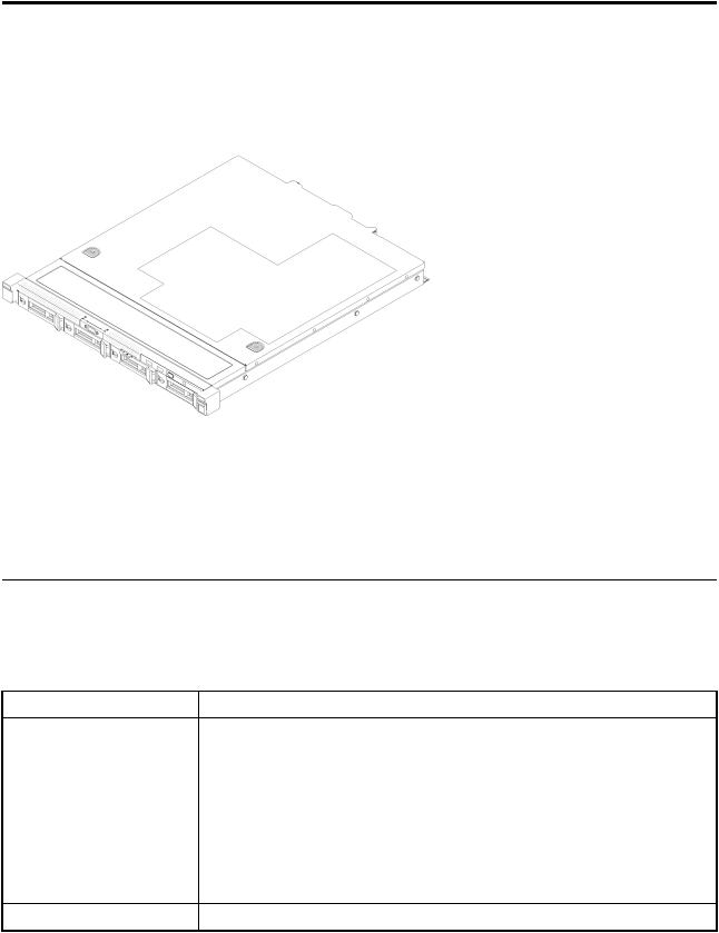
The ThinkSystem SR250 server is a 1U rack server designed for high-volume network transaction processing. This high-performance, multi-core server is ideally suited for networking environments that require superior processor performance, input/output (I/O) flexibility, and high manageability.
Figure 1. SR250
The server comes with a limited warranty. For details about the warranty, see: https://support.lenovo.com/us/en/solutions/ht503310
For details about your specific warranty, see:
http://datacentersupport.lenovo.com/warrantylookup
Specifications
The following information is a summary of the features and specifications of the server. Depending on the model, some features might not be available, or some specifications might not apply.
Table 1. Server Specifications |
|
Specification |
Description |
Size |
1U rack |
|
• Height: 43.0 mm (1.7 inches) |
|
• Width: 434.4 mm (17.1 inches) |
|
– With rack handles: 481.7 mm (18.9 inches) |
|
– Without rack handles: 434.4 mm (17.1 inches) |
|
• Depth: 497.8 mm (19.6 inches) |
|
Note: The depth is measured from the front mounting flange of the rack to the |
|
rear of the server. |
Weight |
Maximum: 12.3 kg (27.1 lbs) |
© Copyright Lenovo 2018 |
1 |

Table 1. Server Specifications (continued)
Specification |
Description |
Processor (depending on the |
One Intel® multi-core processor from Core™, Pentium®, Celeron® or Xeon® E |
model) |
processor family |
Notes:
1.Use the Setup utility to determine the type and speed of the processors in the node.
2.For a list of supported processors, see http://www.lenovo.com/us/en/ serverproven/.
3.If the 95 W processor is used, the server only supports the eight 2.5-inch hotswap drive backplane.
Memory
Drive bays (depending on the model)
M.2 drive
•Slots: 4 DIMM slots
•Minimum: 8 GB (1 x 8GB DIMM)
•Maximum: 64 GB (4 x 16GB DIMM)
•Type:
–PC4-21300, 2666 MT/s, error correcting code (ECC), double-data-rate 4 (DDR4) unbuffered DIMM (UDIMM)
Note: For a list of supported processors, see http://www.lenovo.com/us/en/ serverproven/.
•2.5-inch models:
–Supports up to four simple-swap SAS/SATA drive bays.
–Supports up to eight hot-swap SAS/SATA drive bays.
–Supports up to ten hot-swap SAS/SATA drive bays with two NVMe drive bays.
•3.5-inch models:
–Supports up to four simple-swap SAS/SATA drive bays.
–Supports up to four hot-swap SAS/SATA drive bays.
Notes:
1.When the eighth SATA drive is installed, the M.2 drive is disabled.
2.When all eight storage drives have been installed, and the system has been set to software RAID mode in the UEFI settings, regardless if the disks are configured as an array or as separate disks, drives 6 and 7 cannot be used to install the Windows operating system.
3.If the M.2 drive has been installed, and the system has been set to software RAID mode in the UEFI settings, regardless if the disks are configured as an array or as separate disks, the M.2 drive cannot be used to install the Windows operating system.
Supports 2 different physical sizes of M.2 drives:
•42 mm (2242)
•80 mm (2280)
Notes:
1.When the eighth SATA drive is installed, the M.2 drive is disabled.
2.If the M.2 drive has been installed, and the system has been set to software RAID mode in the UEFI settings, regardless if the disks are configured as an array or as separate disks, the M.2 drive cannot be used to install the Windows operating system.
2 ThinkSystem SR250 Maintenance Manual
Table 1. Server Specifications (continued)
 Specification
PCIe riser cards and expansion slots
Integrated functions
RAID controllers (depending on the model)
 Description
Up to two expansion slots (depending on the sever configuration):
•Slot 1-2: PCI Express 3.0 for PCIe -card with the following slots available depending on the card installed:
1.x16 PCIe (full-height, half-length) kit provides:
–Slot 1: Not available
–Slot 2: PCI Express 3.0 x16
2.x8/x8 butterfly card:
–Slot 1: PCI Express 3.0 x8 (x8, x4, x1), low profile
–Slot 2: PCI Express 3.0 x8 (x8, x4, x1), full-height, half-length
•Slot 4 (on-board): PCI Express 3.0 x8 (x4, x1), low-profile
Notes:
1.PCIe slot 1 and slot 2 do not support ARI and SR-IOV.
2.PCIe slot 4 supports ARI and SR-IOV.
3.QLogic QL41262 PCIe 25Gb 2-Port SFP28 Ethernet Adapter does not support shared storage V3700 V2/XP and V5030 V2 configurations.
•Lenovo XClarity Controller, which provides service processor control and monitoring functions, video controller, and remote keyboard, video, mouse, and remote drive capabilities.
•Light-path diagnostics
•Front standard connectors (front of server):
–One USB 2.0 connector
–One USB 3.1 Gen 1 connector
–One front operator panel
–One VGA connector (optional)
•Rear standard connectors (rear of server):
–Two USB 3.1 Gen 2 connectors
–Two Ethernet connectors
–One Lenovo XClarity Controller network connector
–One VGA connector
–One serial connector
Hardware RAID: Additional RAID levels supported when an optional RAID controller is installed. The hardware RAID controller supports RAID levels 0, 1, 5, and 10.
Software RAID: A software RAID controller is integrated on the system board. The software RAID controller supports RAID levels 0, 1, 5, and 10.
Video controller (integrated |
Matrox G200 |
|
into Lenovo XClarity |
• ASPEED |
|
Controller) |
||
• SVGA compatible video controller |
||
|
||
|
• Avocent Digital Video Compression |
|
|
• 16 MB of video memory (not expandable) |
|
|
Note: Maximum video resolution is 1600 x 1200 at 75 Hz. |
Chapter 1. Introduction 3
Table 1. Server Specifications (continued)
Specification |
Description |
Fans |
Four internal system fans (40mm x 28mm) |
Power supplies |
One fixed power supply: 300-watt ac 80 PLUS Gold |
|
Supports up to two power supplies for redundancy support: 450-watt ac 80 PLUS |
|
Platinum |
Acoustical noise emissions (base configuration)
Heat output
•Operation:
–Minimum: 5.3 bels
–Typical: 5.4 bels
–Maximum: 5.7 bels
•Idle
–Minimum: 4.9 bels
–Typical: 5.0 bels
–Maximum: 5.4 bels
Notes:
1.These sound power levels are measured in controlled acoustical environments according to procedures specified by ISO 7779 and are reported in accordance with ISO 9296.
2.The declared acoustic noise levels are based on specified configurations, which may change slightly depending on configurations/conditions.
3.The options supported in this server vary in function, power consumption, and required cooling. Any increase in cooling required by these options will increase the fan speed and generated sound level. The actual sound pressure levels measured in your installation depend upon a variety of factors, including: the number of racks in the installation; the size, materials, and configuration of the room; the noise levels of other equipment; the room ambient temperature and barometric pressure; and the location of employees in relation to the equipment.
Approximate heat output:
•Minimum configuration: 287.46 BTU per hour (84.25 watts)
•Maximum configuration : 783.02 BTU per hour (229.49 watts)
4 ThinkSystem SR250 Maintenance Manual
Table 1. Server Specifications (continued)
Specification |
Description |
Electrical input |
Sine-wave input (50–60 Hz) required |
|
• 300-Watt power supply: |
|
100-127 V ac /200-240 V ac, 4/2A |
|
• 450-Watt power supply: |
|
100-127 V ac /200-240 V ac, 5.8/2.9A |
Environment |
The ThinkSystem SR250 complies with ASHRAE class A2 specifications. System |
|
performance may be impacted when operating temperature is outside ASHRAE A2 |
|
specification or fan failed condition. |
|
The ThinkSystem SR250 is supported in the following environment: |
|
• Air temperature: |
|
– Server on: |
|
– (ASHRAE Class A2): 10°C to 35°C (50°F to 95°F); decrease the maximum |
|
ambient temperature by 1°C for every 300 m (984 ft) increase in altitude |
|
above 900 m (2,953 ft). |
|
– Sever off: 5°C to 45°C (41°F to 113°F) |
|
– Shipping/storage: -40 - 60°C (-40 - 140°F) |
|
• Maximum altitude: 3050 m (10 000 ft) |
|
• Relative Humidity (non-condensing): |
|
– Operating: |
|
– ASHRAE Class A2: 8% - 80%, maximum dew point : 21°C (70°F) |
|
– Shipment/storage: 8% to 90% |
|
• ASHRAE A3 is supported for the eight 2.5-inch hot-swap drive configuration with |
|
80W processor only. |
|
• Particulate contamination: |
|
Airborne particulates and reactive gases acting alone or in combination with other |
|
environmental factors such as humidity or temperature might pose a risk to the |
|
solution. For information about the limits for particulates and gases, see |
|
“Particulate contamination” on page 170. |
Firmware updates
Several options are available to update the firmware for the server.
You can use the tools listed here to update the most current firmware for your server and the devices that are installed in the server.
Note: Lenovo typically releases firmware in bundles called UpdateXpress System Packs (UXSPs). To ensure that all of the firmware updates are compatible, you should update all firmware at the same time. If you are updating firmware for both the Lenovo XClarity Controller and UEFI, update the firmware for Lenovo XClarity Controller first.
Best practices related to updating firmware is available at the following location:
http://lenovopress.com/LP0656
Chapter 1. Introduction 5

Important terminology
•In-band update The installation or update is performed using a tool or application within. an operating system that is executing on the server’s core CPU.
•Out-of-band update The installation or update is performed by the Lenovo XClarity Controller. collecting the update and then directing the update to the target subsystem or device. Out-of-band updates have no dependency on an operating system executing on the core CPU. However, most out-of-band operations do require the server to be in the S0 (Working) power state.
•On-Target update. The installation or update is initiated from an Operating System executing on the server’s operating system.
•Off-Target update. The installation or update is initiated from a computing device interacting directly with the server’s Lenovo XClarity Controller.
• UpdateXpress System Packs (UXSPs) UXSPs are bundled updates designed and tested to provide the |
. |
interdependent level of functionality, performance, and compatibility. UXSPs are server machine-type |
|
specific and are built (with firmware and device driver updates) to support specific Windows Server, Red |
|
Hat Enterprise Linux (RHEL) and SUSE Linux Enterprise Server (SLES) operating system distributions. |
|
Machine-type-specific firmware-only UXSPs are also available. |
|
See the following table to determine the best Lenovo tool to use for installing and setting up the firmware: |
|
Note: The server UEFI settings for option ROM must be set to Auto or UEFI to update firmware using |
|
Lenovo XClarity Administrator or Lenovo XClarity Essentials. For more information, see the following Tech |
|
Tip: |
|
https://datacentersupport.lenovo.com/us/en/solutions/ht506118
|
|
Out-of- On- |
Off- |
Graphical |
|
|
|
|
In-band |
band |
target |
target |
user |
Command- |
Supports |
Tool |
update |
update |
update |
update |
interface |
line interface |
UXSPs |
Lenovo XClarity |
√ |
|
|
√ |
√ |
|
√ |
Provisioning |
|
|
|
|
|
|
|
Manager |
|
|
|
|
|
|
|
Limited to core system |
|
|
|
|
|
|
|
firmware only. |
|
|
|
|
|
|
|
Lenovo XClarity |
|
√ |
|
√ |
√ |
√ |
|
Controller |
|
|
|
|
|
|
|
Supports core system |
|
|
|
|
|
|
|
firmware and most |
|
|
|
|
|
|
|
advanced I/O option |
|
|
|
|
|
|
|
firmware updates |
|
|
|
|
|
|
|
Lenovo XClarity |
√ |
√ |
|
|
|
√ |
√ |
Essentials OneCLI
Supports all core system firmware, I/O firmware, and installed operating system driver updates
6 ThinkSystem SR250 Maintenance Manual

|
|
Out-of- On- |
Off- |
Graphical |
|
|
|
|
In-band |
band |
target |
target |
user |
Command- |
Supports |
Tool |
update |
update |
update |
update |
interface |
line interface |
UXSPs |
Lenovo XClarity |
√ |
√ |
|
|
√ |
|
√ |
Essentials |
|
|
|
|
|
|
|
UpdateXpress |
|
|
|
|
|
|
|
Supports all core |
|
|
|
|
|
|
|
system firmware, I/O |
|
|
|
|
|
|
|
firmware, and installed |
|
|
|
|
|
|
|
operating system |
|
|
|
|
|
|
|
driver updates |
|
|
|
|
|
|
|
Lenovo XClarity |
√ |
|
|
|
√ |
√ |
√ |
Essentials Bootable |
|
|
|
|
|
|
|
Media Creator |
|
|
|
|
|
|
|
Supports core system |
|
|
|
|
|
|
|
firmware and I/O |
|
|
|
|
|
|
|
firmware updates. You |
|
|
|
|
|
|
|
can update the |
|
|
|
|
|
|
|
Microsoft Windows |
|
|
|
|
|
|
|
operating system, but |
|
|
|
|
|
|
|
device drivers are not |
|
|
|
|
|
|
|
included on the |
|
|
|
|
|
|
|
bootable image |
|
|
|
|
|
|
|
Lenovo XClarity |
√ |
√ |
|
√ |
√ |
|
|
Administrator |
|
|
|
|
|
|
|
Supports core system firmware and I/O firmware updates
The latest firmware can be found at the following site:
http://datacentersupport.lenovo.com/us/en/products/servers/system-x/system-x3850-x6/6241/downloads
•Lenovo XClarity Provisioning Manager
From Lenovo XClarity Provisioning Manager, you can update the Lenovo XClarity Controller firmware, the UEFI firmware, and the Lenovo XClarity Provisioning Manager software.
Note: By default, the Lenovo XClarity Provisioning Manager Graphical User Interface is displayed when you press F1. If you have changed that default to be the text-based system setup, you can bring up the Graphical User Interface from the text-based system setup interface.
Additional information about using Lenovo XClarity Provisioning Manager to update firmware is available at:
http://sysmgt.lenovofiles.com/help/topic/LXPM/platform_update.html
•Lenovo XClarity Controller
If you need to install a specific update, you can use the Lenovo XClarity Controller interface for a specific server.
Notes:
–To perform an in-band update through Windows or Linux, the operating system driver must be installed and the Ethernet-over-USB (sometimes called LAN over USB) interface must be enabled.
Additional information about configuring Ethernet over USB is available at:
Chapter 1. Introduction 7
http://sysmgt.lenovofiles.com/help/topic/com.lenovo.systems.management.xcc.doc/NN1ia_c_ configuringUSB.html
–If you update firmware through the Lenovo XClarity Controller, make sure that you have downloaded and installed the latest device drivers for the operating system that is running on the server.
Specific details about updating firmware using Lenovo XClarity Controller are available at:
http://sysmgt.lenovofiles.com/help/topic/com.lenovo.systems.management.xcc.doc/NN1ia_c_ manageserverfirmware.html
•Lenovo XClarity Essentials OneCLI
Lenovo XClarity Essentials OneCLI is a collection of command line applications that can be used to manage Lenovo servers.Its update application can be used to update firmware and device drivers for your servers. The update can be performed within the host operating system of the server (in-band) or remotely through the BMC of the server (out-of-band).
Specific details about updating firmware using Lenovo XClarity Essentials OneCLI is available at: http://sysmgt.lenovofiles.com/help/topic/toolsctr_cli_lenovo/onecli_c_update.html
•Lenovo XClarity Essentials UpdateXpress
Lenovo XClarity Essentials UpdateXpress provides most of OneCLI update functions through a graphical user interface (GUI). It can be used to acquire and deploy UpdateXpress System Pack (UXSP) update packages and individual updates. UpdateXpress System Packs contain firmware and device driver updates for Microsoft Windows and for Linux.
You can obtain Lenovo XClarity Essentials UpdateXpress from the following location: https://datacentersupport.lenovo.com/solutions/lnvo-xpress
•Lenovo XClarity Essentials Bootable Media Creator
You can use Lenovo XClarity Essentials Bootable Media Creator to create bootable media that is suitable for applying firmware updates, running preboot diagnostics, and deploying Microsoft Windows operating systems.
You can obtain Lenovo XClarity Essentials BoMC from the following location: https://datacentersupport.lenovo.com/solutions/lnvo-bomc
•Lenovo XClarity Administrator
If you are managing multiple servers using the Lenovo XClarity Administrator, you can update firmware for all managed servers through that interface. Firmware management is simplified by assigning firmwarecompliance policies to managed endpoints. When you create and assign a compliance policy to managed endpoints, Lenovo XClarity Administrator monitors changes to the inventory for those endpoints and flags any endpoints that are out of compliance.
Specific details about updating firmware using Lenovo XClarity Administrator are available at: http://sysmgt.lenovofiles.com/help/topic/com.lenovo.lxca.doc/update_fw.html
Configuring the LAN over USB interface manually
To perform a firmware update through the operating system using Lenovo XClarity Essentials OneCLI, the Lenovo XClarity Controller must be configured to use the LAN over USB interface. The firmware update package attempts to perform the setup automatically, if needed. If the automatic setup fails or if you prefer to set up the LAN over USB manually, use one of the following procedures.
Additional information about using the Lenovo XClarity Controller to enable LAN over USB is available at:
8 ThinkSystem SR250 Maintenance Manual

http://sysmgt.lenovofiles.com/help/topic/com.lenovo.systems.management.xcc.doc/NN1ia_c_ configuringUSB.html
Installing the LAN over USB Windows device driver
When you install a Windows operating system, there might be an unknown RNDIS device in the Device Manager. Lenovo provides a Windows INF file that identifies this device.
Complete the following steps to install ibm_rndis_server_os.inf |
: |
Note: You only have to perform these steps if the compute node is running a Windows operating system and the ibm_rndis_server_os.inf file has not been previously installed. The file only has to be installed once. It
is required by Windows operating systems to detect and use the LAN over USB functionality.
Step 1. Click Administrative Tools Computer Management Device Manager and find the RNDIS |
|
|||
|
Device. Click Properties Driver Reinstall driver |
Point the server to the \Windows\inf |
. |
|
|
directory where it can find the ibm_rndis_server_os.inf file and install the device. |
|
|
|
Step 2. |
Click Administrative Tools Device Manager Right-click Network adapters and select Scan |
|
||
|
for hardware changes A small pop-up confirms that the Ethernet device is found and installed. |
. |
||
|
The New Hardware Wizard starts automatically. |
|
|
|
Step 3. |
When you are prompted Can Windows connect to Windows Update to search for software? select No, |
|
||
|
not this time Click Next to continue. |
. |
|
|
Step 4. |
When you are prompted What do you want the wizard to do? select Install from a list or specific, |
|
||
|
location (Advanced) Click Next to continue. |
|
|
|
Step 5. When you are prompted Please choose your search and installation options, select Don't search. I |
|
|||
|
will choose the driver to install Click Next to continue. |
. |
|
|
Step 6. |
When you are prompted Select a hardware type, and then click Next select Network, |
adapters |
|
|
|
Click Next to continue. |
|
|
|
Step 7. |
When you are prompted with the statement Completing the Found New Hardware Wizard click Finish |
|
||
|
A new local area connection appears. If the message This connection has limited or no |
|
||
|
connectivity is displayed, ignore this message. |
|
|
|
Step 8. Return to the Device Manager. Lenovo USB Remote NDIS Network Device appears under |
|
|||
|
Network Adapters |
|
|
. |
Step 9. Use the Lenovo XClarity Controller interface to view or set the IP address for the LAN adapter.
Additional information about using the Lenovo XClarity Controller to configure LAN over USB is available at:
http://sysmgt.lenovofiles.com/help/topic/com.lenovo.systems.management.xcc.doc/NN1ia_c_ configuringUSB.html
Tech Tips
Lenovo continually updates the support website with the latest tips and techniques that you can use to solve issues that you might have with your server. These Tech Tips (also called retain tips or service bulletins) provide procedures to work around issues related to the operation of your server.
To find the Tech Tips available for your server:
1.Go to http://datacentersupport.lenovo.com and navigate to the support page for your server.
2.Click How-tos & Solutions
Expand Symptom to choose a category for the type is problem that you are having.
Chapter 1. Introduction 9

Security advisories
Lenovo is committed to developing products and services that adhere to the highest security standards in order to protect our customers and their data. When potential vulnerabilities are reported, it is the responsibility of the Lenovo Product Security Incident Response Team (PSIRT) to investigate and provide information to our customers so they may put mitigation plans in place as we work toward providing solutions.
The list of current advisories is available at the following site:
https://datacentersupport.lenovo.com/product_security/home
Power on the server
After the server performs a short self-test (power status LED flashes quickly) when connected to input power, it enters a standby state (power status LED flashes once per second).
The server can be turned on (power LED on) in any of the following ways:
•You can press the power button.
•The server can restart automatically after a power interruption.
•The server can respond to remote power-on requests sent to the Lenovo XClarity Controller.
For information about powering off the server, see “Power off the server” on page 10.
Power off the server
The server remains in a standby state when it is connected to a power source, allowing the Lenovo XClarity Controller to respond to remote power-on requests. To remove all power from the server (power status LED off), you must disconnect all power cables.
To place the server in a standby state (power status LED flashes once per second):
Note: The Lenovo XClarity Controller can place the server in a standby state as an automatic response to a critical system failure.
•Start an orderly shutdown using the operating system (if supported by your operating system).
•Press the power button to start an orderly shutdown (if supported by your operating system).
•Press and hold the power button for more than 4 seconds to force a shutdown.
When in a standby state, the server can respond to remote power-on requests sent to the Lenovo XClarity Controller. For information about powering on the server, see “Power on the server” on page 10.
10 ThinkSystem SR250 Maintenance Manual
Chapter 2. Server components
Use the information in this section to learn about each of the components associated with your server.
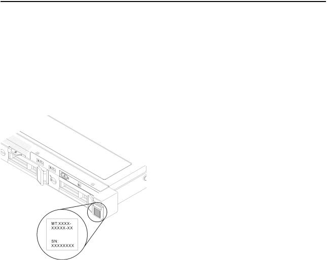
Identifying your server
When you contact Lenovo for help, the machine type, model, and serial number information helps support technicians to identify your server and provide faster service.
The model number and serial number are on the ID label on the front of the server. The following illustration shows the location of the ID label containing the machine type, model, and serial number.
Figure 2. Location of the machine type, model, and serial number
Network access tag
The network access tag can be found on the front of the server. You can pull way the network access tag to paste your own label for recording some information such as the hostname, the system name and the inventory bar code. Please keep the network access tag for future reference.
© Copyright Lenovo 2018 |
11 |
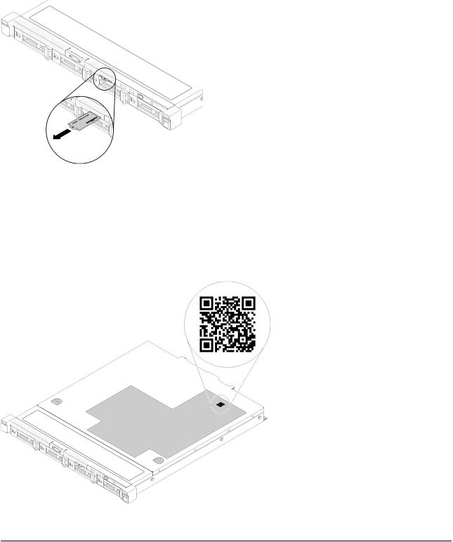
Figure 3. Network access tag
QR code
In addition, the system Service Card that is located on the top cover of the server, provides a quick reference (QR) code for mobile access to service information. You can scan the QR code with a mobile device using a QR code reader application and get quick access to the Service Information web page. The Service Information web page provides additional information for parts installation and replacement videos, and error codes for server support.
Figure 4. SR250 QR code
Front view
The front view of the server varies by the model.
12 ThinkSystem SR250 Maintenance Manual
Front view of the server
Figure 5. Four simple-swap drives model front view
Table 2. Components on the four simple-swap drives model front view
1 |
VGA connector (optional) |
4 |
Front operator panel |
2 |
USB 2.0 connector |
5 |
Four simple-swap drive bays (0-3) |
3 |
USB 3.1 Gen 1 connector |
6 |
Rack release latches |
Figure 6. Four hot-swap drives model front view
Table 3. Components on the four hot-swap drives model front view
1 |
VGA connector (optional) |
4 |
Front operator panel |
2 |
USB 2.0 connector |
5 |
Four hot-swap drive bays (0-3) |
3 |
USB 3.1 Gen 1 connector |
6 |
Rack release latches |
Figure 7. Eight 2.5-inch hot-swap drives model front view
Table 4. Components on the eight 2.5-inch hot-swap drives model front view
1 |
USB 2.0 connector |
4 |
VGA connector (optional) |
2 |
USB 3.1 Gen 1 connector |
5 |
Eight 2.5-inch hot-swap drive bays (0-7) |
3 |
Front operator panel |
6 |
Rack release latches |
Chapter 2. Server components 13
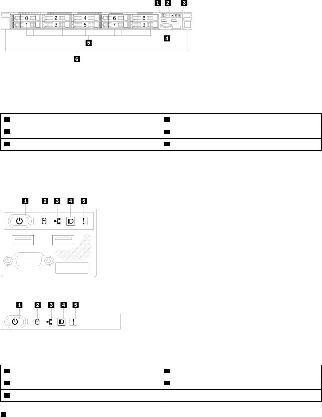
Figure 8. Ten 2.5-inch hot-swap drives model front view
Note: The last two drive bays may not be supported if only the eight-bay backplane is installed.
Table 5. Components on the ten 2.5-inch hot-swap drives model front view
1 |
USB 2.0 connector |
4 |
VGA connector (optional) |
2 |
USB 3.1 Gen 1 connector |
5 |
Ten 2.5-inch hot-swap drive bays (0-9) |
3 |
Front operator panel |
6 |
Rack release latches |
Front operator panel
The front operator information panel of the server provides controls, connectors, and LEDs. The front operator panel varies by model.
Figure 9. 2.5-inch drive chassis front I/O assembly
Figure 10. 3.5-inch drive chassis front operator panel |
|
|
|
Table 6. Front operator panel controls and indicators |
|
|
|
1 |
Power button and power LED (green) |
4 |
System ID button/LED (blue) |
2 |
Drive activity LED (green) |
5 |
System-error LED (yellow) |
3 |
Network activity LED (green) |
|
|
1 Power button and power LED (green): Press this button to turn the server on and off manually. The states of the power LED are as follows:
Off: Power is not present or the power supply, or the LED itself has failed.
14 ThinkSystem SR250 Maintenance Manual
Flashing rapidly (4 times per second): The server is turned off and is not ready to be turned on. The power button is disabled. This will last approximately 5 to 10 seconds.
Flashing slowly (once per second): The server is turned off and is ready to be turned on. You can press the power button to turn on the server.
On: The server is turned on.
2Drive activity LED (green): Each hot-swap drive comes with an activity LED. If the LED is lit, it indicates that the drive is powered, but not actively reading or writing data. If the LED is flashing, the drive is being accessed.
3Network activity LED (green): When this LED flickers, it indicates that the server is transmitting to or receiving signals from the Ethernet LAN.
4System ID button/LED (blue): Use this blue LED to visually locate the server among other servers. This LED is also used as a presence detection button. You can use Lenovo XClarity Administrator to light this LED remotely.
5System-error LED (yellow): When this yellow LED is lit, it indicates that a system error has occurred.
Rear view
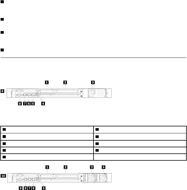
The rear of the server provides access to several components, including the power supplies, PCIe adapters, serial port, and Ethernet port.
Figure 11. Rear view - Non-redundant power supply model |
|
|
|
Table 7. Rear view - Non-redundant power supply model |
|
|
|
1 |
PCIe slot 1 |
6 |
Ethernet connector 1 (shared with XCC network port) |
2 |
PCIe slot 2 |
7 |
Dedicated XClarity Controller (XCC) network connector |
3 |
Power connector |
8 |
VGA connector |
4 |
USB 3.1 Gen 2 connectors |
9 |
Serial connector |
5 |
Ethernet connector 2 |
|
|
Figure 12. Rear view - Redundant power supply model
Chapter 2. Server components 15
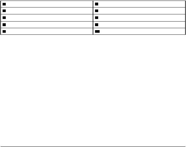
Table 8. Rear view - Redundant power supply model |
|
|
|
1 |
PCIe slot 1 |
6 Ethernet connector 2 |
|
2 |
PCIe slot 2 |
7 Ethernet connector 1 (shared with XCC network port) |
|
3 |
Power connector 1 |
8 Dedicated XClarity Controller (XCC) network connector |
|
4 |
Power connector 2 |
9 VGA connector |
|
5 |
USB 3.1 Gen 2 connectors |
10 Serial connector |
|
PCIe slot 1 and 2 Your server: has PCIe slots on the system board for you to install appropriate PCIe |
|
||
adapters. For information about the PCIe slots, see “PCIe riser assembly” on page 23. |
|
||
Power connector 1 and 2 Connect the: power cord to this component. |
|
||
USB 3.1 Gen 2 connectors Used to attach a device that requires a USB 3.1 connection, such as a |
|
||
keyboard, a mouse, or a USB flash drive. |
|
|
|
Ethernet connector 1 and 2 Used to attach: an Ethernet cable for a LAN. Each Ethernet connector has two |
|
||
status LEDs to help you identify the Ethernet connectivity and activity. If the LOM adapter is not installed, |
|
||
Ethernet connector 1 can be set as XClarity Controller Network connector. To set Ethernet connector 1 as |
|
||
XClarity Controller Network connector, start Setup Utility and select BMC Settings Network Settings |
|
||
Network Settings Network Interface Port : Shared Then, click Shared NIC on and select Onboard Port |
. |
||
1 |
. |
|
|
Dedicated XClarity Controller (XCC) network connector : Used to attach an Ethernet cable to manage the |
|
||
system using XClarity Controller. |
|
|
|
VGA connector : Used to attach a VGA-compatible video device, such as a VGA monitor. |
|
||
Serial connector Connect a 9-pin serial device to this connector. The serial port is shared with the XCC. |
: |
||
The XCC can take control of the shared serial port to redirect serial traffic, using Serial over LAN (SOL). |
|
||
System-board switches, jumpers, and buttons
The illustrations in this section provide information about the switches, jumpers, and buttons that are available on the system board.
For more information about the LEDs that are available on the system board, see “System-board LEDs” on page 16.
System-board LEDs
The following illustrations show the light-emitting diodes (LEDs) on the system board.
16 ThinkSystem SR250 Maintenance Manual
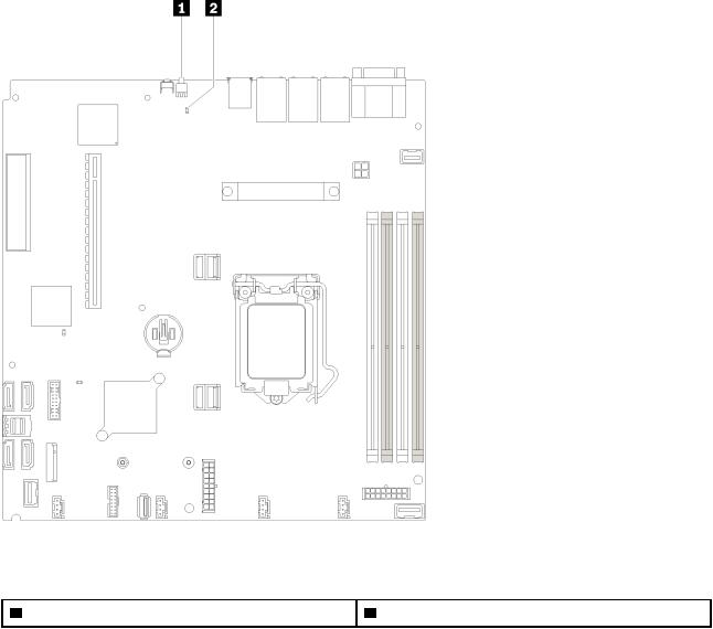
Figure 13. System-board LEDs |
|
Table 9. System-board LEDs |
|
1 Rear identification LED (blue) |
2 System error LED (yellow) |
System-board connectors
The following illustrations show the connectors on the system board.
Chapter 2. Server components 17

Figure 14. System-board connectors |
|
|
|
Table 10. System-board connectors |
|
|
|
1 |
USB 3.1 Gen 1 connector |
15 |
Fan 3 connector |
2 |
Lan 2 connector |
16 |
Internal USB 3.1 Gen 1 connector |
3 |
Lan 1 connector (shared with XCC) |
17 |
TPM card/TPM connector |
4 |
Dedicated XClarity Controller (XCC) network connector |
18 |
M.2 backplane connector |
5 |
VGA and serial port connector |
19 |
Fan 4 connector |
6 |
Processor power connector |
20 |
Front panel connector |
7 |
Front VGA connector |
21 |
SATA connector 6 |
8 |
DIMM slot 1-4 |
22 |
SATA connector 7 |
9 |
Processor |
23 |
SATA connector 0-3 |
10 Backplane power connector |
24 |
SATA connector 4 |
|
11 PIB signal connector |
25 |
SATA connector 5 |
|
12 Fan 1 connector |
26 |
CMOS battery - CR2032 |
|
13 Fan 2 connector |
27 |
slot |
|
14 System power connector |
28 |
PCIe3x 8 (4,1) - slot 4 |
|
18 ThinkSystem SR250 Maintenance Manual
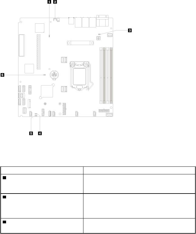
System-board jumpers and buttons
The following illustrations show the location of the jumpers and buttons on the server.
Note: If there is a clear protective sticker on the top of the switch blocks, you must remove and discard it to access the switches.
Figure 15. System-board jumpers and buttons
The following table describes the jumpers and buttons on the system board.
Table 11. System-board jumpers and buttons |
|
Jumper and button name |
Jumper setting / Button function |
1 Force XCC update jumper |
• Pins 1 and 2: Normal (default). |
|
2Force NMI button
3NCSI functional header jumper
•Pins 2 and 3: Force the Lenovo XClarity Controller to update to the latest version.
This button is on the rear of the server. Press this button to force a nonmaskable interrupt to the processor. You might have to use a pen or the end of a straightened paper clip to press the button. You can also use it to force a blue-screen memory dump (use this button only when you are directed to do so by Lenovo Support).
•Pins 1 and 2: Normal (default).
•Pins 2 and 3: Disable
Chapter 2. Server components 19
Table 11. System-board jumpers and buttons (continued)
 Jumper and button name
4Power permission override jumper
5Clear CMOS jumper
6TPM/TPM card physical presence jumper
 Jumper setting / Button function
•Pins 1 and 2: Normal (default).
•Pins 2 and 3: Override the power-on permission.
•Pins 1 and 2: Normal (default).
•Pins 2 and 3: Clear the real-time clock (RTC) registry.
•Pins 1 and 2: Normal (default).
•Pins 2 and 3: TPM/TPM card physical presence is asserted.
Important:
1.Before you change any switch settings or move any jumpers, turn off the server; then, disconnect all power cords and external cables. Review the information in http://thinksystem.lenovofiles.com/help/topic/ safety_documentation/pdf_files.html, “Installation Guidelines” on page 47, “Handling static-sensitive devices” on page 49, and “Power off the server” on page 10.
2.Any system-board switch or jumper block that is not shown in the illustrations in this document are reserved.
RAID adapters and the NVMe switch card
Use this information to locate the connectors on the RAID adapters and the NVMe switch card.
20 ThinkSystem SR250 Maintenance Manual
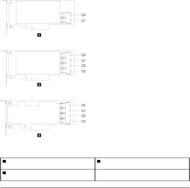
Connectors on RAID adapters and the NVMe switch card
Figure 16. Connectors on RAID adapters and the NVMe switch card
Table 12. Connectors on RAID adapters and the NVMe switch card
1SATA/SAS RAID adapter (8i) with two SATA/SAS connectors (C0, C1)
2SATA/SAS RAID adapter (16i) with four SATA/SAS connectors (C0, C1, C2, C3)
3 PCIe switch card with four connectors (C0, C1, C2, C3)
Backplates and backplanes
Use this information to identify the backplate or the backplane you use.
Chapter 2. Server components 21
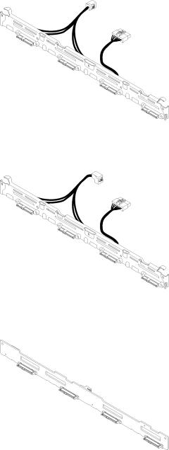
Backplate, four 3.5-inch simple-swap drives (connects to RAID adapter)
Figure 17. Backplate, four 3.5-inch simple-swap drives (connects to RAID adapter)
Backplate, four 3.5-inch simple-swap drives (connects to onboard connectors)
Figure 18. Backplate, four 3.5-inch simple-swap drives (connects to onboard connectors)
Backplane, four 3.5-inch hot-swap drives
Figure 19. Backplane, four 3.5-inch hot-swap drives
22 ThinkSystem SR250 Maintenance Manual
Loading...