


S20
Table of contents
 Loading...
ThinkStation
HardwareInstallationandReplacementGuide
MachineTypes:4105,4157,and4217

Note:Beforeusingthisinformationandtheproductitsupports,besuretoreadandunderstandthe
ThinkStationSafetyandWarrantyGuideforthisproductandAppendixB“Notices”onpage53.
SecondEdition(September2011)
©CopyrightLenovo2009,2011.
LIMITEDANDRESTRICTEDRIGHTSNOTICE:IfdataorsoftwareisdeliveredpursuantaGeneralServicesAdministration
“GSA”contract,use,reproduction,ordisclosureissubjecttorestrictionssetforthinContractNo.GS-35F-05925.

Contents
Figures................iii
Chapter1.Importantsafety
information...............1
Chapter2.Overview...........3
Additionalinformationresources........3
Handlingstatic-sensitivedevices........3
Locations..................4
Locatingcontrolsandconnectorsonthefront
ofyourcomputer.............4
Locatingconnectorsontherearofyour
computer................5
Locatinginternalcomponents........7
Identifyingpartsonthesystemboard.....8
Chapter3.Installingoptionsand
replacinghardware..........11
Installingexternaloptions..........11
Installinginternaloptions..........11
Removingthecomputercover.......11
Removingthefrontbezel.........12
Accessingsystemboardcomponents....13
Installingamemorymodule........13
Installinganadaptercard.........14
Installinginternaldrives.........16
Replacingthebattery............23
Replacingthepowersupplyassembly.....24
Replacinganadaptercard..........27
Replacingtheheatsinkandfanassembly....31
Replacingaharddiskdrive..........33
Replacingtheharddiskdrivefanassembly...34
Replacinganopticaldrive..........36
Replacingthediskettedriveorcardreader...37
Replacingthefrontpanelconnectorassembly..39
Replacingamemorymodule.........40
Replacingthefrontandrearfanassemblies...41
Replacingtheinternalspeaker........42
Replacingthekeyboard...........44
Replacingthemouse............44
Chapter4.Completingtheparts
replacement..............47
Obtainingdevicedrivers...........47
Chapter5.Securityfeatures.....49
Lockingdevices..............49
Passwordprotection............50
Erasingalostorforgottenpassword(clearing
CMOS)..................50
AppendixA.Systemmemoryspeed.51
AppendixB.Notices..........53
Televisionoutputnotice...........54
Trademarks................54
Index..................55
©CopyrightLenovo2009,2011
i

iiThinkStationHardwareInstallationandReplacementGuide

Figures
1.Frontcontrolsandconnectors.......4
2.Rearconnectorlocations.........5
3.Componentlocations...........7
4.Systemboardpartslocations.......8
5.Removingthecomputercover......12
6.Removingthefrontbezel........13
7.Openingtheretainingclips.......14
8.Installingthememorymodule......14
9.Installinganadaptercard........15
10.Drivebaylocations...........17
11.Installingtheretainerbracket.......18
12.Installinganopticaldrive........18
13.Connectingthedrive..........19
14.Installingtheretainerbracket.......19
15.Installinganewdiskettedriveorcard
reader................20
16.Installinga3.5-inchharddiskdriveintothe
bracket...............21
17.Installinga2.5-inchharddiskdriveintothe
bracket...............21
18.Installingtheharddiskdriveandbracketinto
thedrivebay.............22
19.Connectinga3.5-inchSA T Aharddisk
drive................22
20.Connectinga2.5-inchSA T Aharddisk
drive................23
21.Connectinga3.5-inchSASharddisk
drive................23
22.Removingtheoldbattery........24
23.Installingthenewbattery........24
24.Powersupplycableconnectors......25
25.Removingthepowersupplyretaining
screws...............26
26.Removingthepowersupply.......27
27.Installinganewadaptercard.......30
28.Removingtheheatsinkandfan
assembly..............32
29.Removingaharddiskdrive.......34
30.Removingtheharddiskdrivefan
assembly..............35
31.Installingtheharddiskdrivefan
assembly..............36
32.Removingtheopticaldrive........37
33.Retainerbracketforopticaldrive.....37
34.Removingthediskettedriveorcard
reader................38
35.Installingadiskettedriveorcardreader..39
36.Removingthefrontpanelconnector
assembly..............40
37.Removingamemorymodule.......41
38.Installingthememorymodule......41
39.Removingtherearfanassembly.....42
40.Removingtheinternalspeaker......43
41.Keyboardconnector..........44
42.Mouseconnector...........45
43.Lockingdevices............49
©CopyrightLenovo2009,2011
iii

ivThinkStationHardwareInstallationandReplacementGuide

Chapter1.Importantsafetyinformation
CAUTION:
Beforeusingthismanual,itisimportantthatyoureadandunderstandalltherelatedsafety
informationforthisproduct.RefertotheThinkStationSafetyandWarrantyGuidethatyoureceived
withthisproductforthelatestsafetyinformation.Readingandunderstandingthesafetyinformation
reducestheriskofpersonalinjuryandordamagetoyourproduct.
IfyounolongerhaveacopyoftheThinkStationSafetyandWarrantyGuide,youcanobtainaPortable
DocumentFormat(PDF)versionfromtheLenovo
http://support.lenovo.com
®
SupportWebsiteat:
©CopyrightLenovo2009,2011
1

2ThinkStationHardwareInstallationandReplacementGuide

Chapter2.Overview
ThisguideprovidesinformationaboutinstallingandorreplacingCustomerReplaceableUnits(CRUs).
However,thisguidedoesnotincludeproceduresforallparts.Itisexpectedthatcables,switches,andcertain
mechanicalpartsbereplacedbytrainedservicepersonnelwithouttheneedforstep-by-stepprocedures.
Note:UseonlypartsprovidedbyLenovo.
Thisguidecontainsinstructionsforinstallingorreplacingthefollowingparts:
•Battery
•Powersupply
•Adaptercard
•Heatsinkandfanassembly
•Harddiskdrive
•Harddiskdrivefanassembly
•Opticaldrive
•Diskettedriveorcardreader
•Frontpanelconnectorassembly
•Memorymodule
•Frontandrearfanassemblies
•Internalspeaker
•Keyboard
•Mouse
Additionalinformationresources
IfyouhaveInternetaccess,themostup-to-dateinformationforyourcomputerisavailableat:
http://support.lenovo.com
Youcannd:
•CRUremovalandinstallationinformation
•CRUremovalandinstallationvideos
•Downloadsanddrivers
•Linkstootherusefulsourcesofinformation
•Partsinformation
•Publications
•Supportphonelist
•T roubleshootinginformation
Handlingstatic-sensitivedevices
Donotopenthestatic-protectivepackagecontainingthenewpartuntilthedefectiveparthasbeenremoved
fromthecomputerandyouarereadytoinstallthenewpart.Staticelectricity,althoughharmlesstoyou,can
seriouslydamagecomputercomponentsandparts.
©CopyrightLenovo2009,2011
3
Whenyouhandlepartsandothercomputercomponents,taketheseprecautionstoavoidstatic-electricity
damage:
•Limityourmovement.Movementcancausestaticelectricitytobuilduparoundyou.
•Alwayshandlepartsandothercomputercomponentscarefully.Handleadaptercards,memorymodules,
systemboards,andmicroprocessorsbytheedges.Nevertouchanyexposedcircuitry.
•Preventothersfromtouchingthepartsandothercomputercomponents.
•Beforeyoureplaceanewpart,touchthestatic-protectivepackagecontainingtheparttoametal
expansion-slotcoverorotherunpaintedmetalsurfaceonthecomputerforatleasttwoseconds.This
reducesstaticelectricityinthepackageandyourbody.
•Whenpossible,removethenewpartfromthestatic-protectivepackaging,andinstallitdirectlyinthe
computerwithoutsettingthepartdown.Whenthisisnotpossible,placethestatic-protectivepackage
thatthepartcameinonasmooth,levelsurfaceandplacethepartonit.
•Donotplacethepartonthecomputercoverorothermetalsurface.
Locations
Thissectioncontainsillustrationstohelplocatethevariousconnectors,controls,andcomponentsofthe
computer.
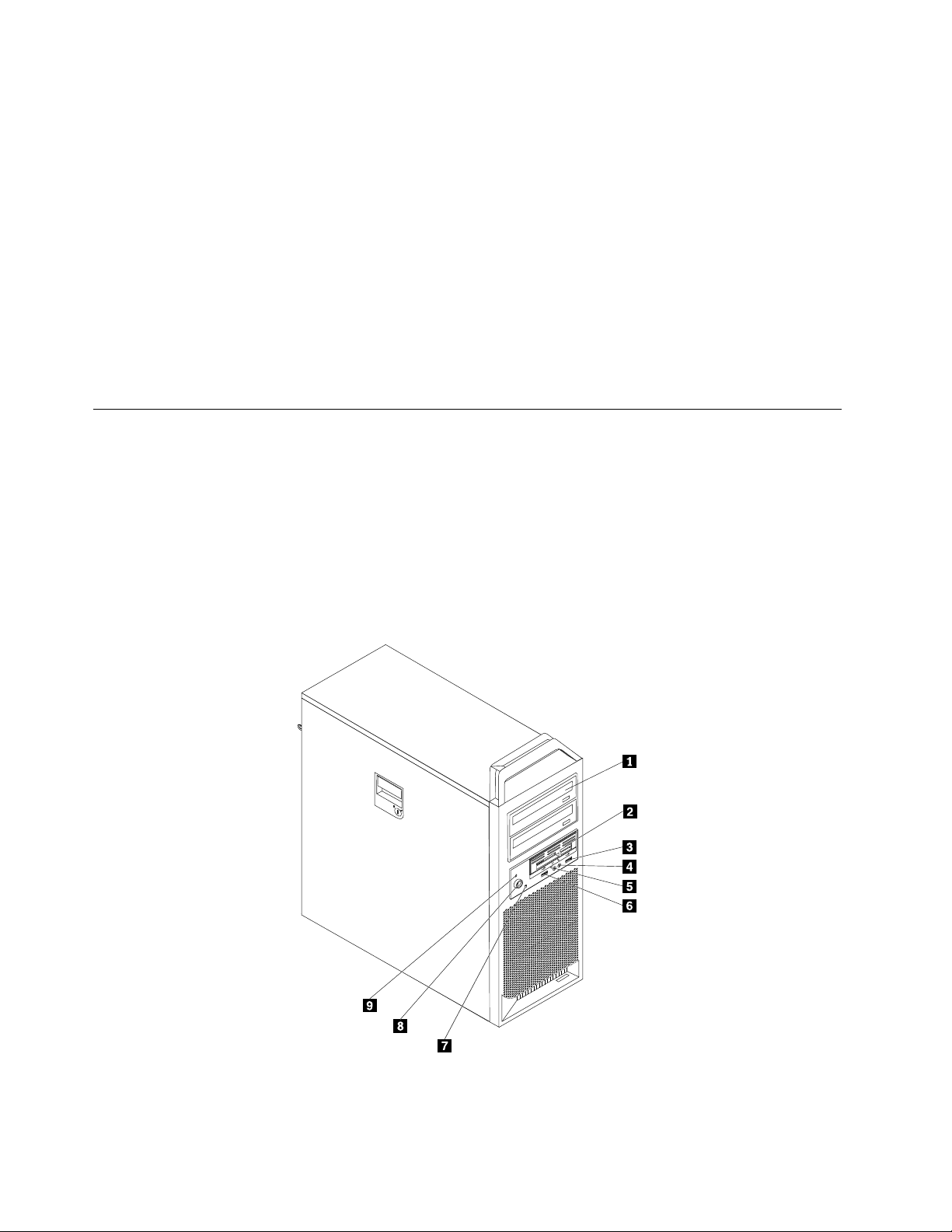
Locatingcontrolsandconnectorsonthefrontofyourcomputer
Figure1“Frontcontrolsandconnectors”onpage4showsthelocationoftheconnectorsonthefront
ofyourcomputer.
Note:Notallcomputermodelshavethefollowingcontrolsandconnectors.
Figure1.Frontcontrolsandconnectors
4ThinkStationHardwareInstallationandReplacementGuide

1Opticaldrive(somemodels)6USBconnector
23.5-inchdiskettedriveorcardreader(some
7Harddiskdriveactivitylight
models)
3USBconnector
4Microphoneconnector9Power-onindicator
5Headphoneconnector
8Powerbutton
Locatingconnectorsontherearofyourcomputer
Figure2“Rearconnectorlocations”onpage5showsthelocationoftheconnectorsontherearofyour
computer.Someconnectorsontherearofyourcomputerarecolor-codedtohelpyoudeterminewhereto
connectthecablesonyourcomputer.
Figure2.Rearconnectorlocations
1Powercordconnector9Microphoneconnector
2Serialport
3Ethernetconnector11Audioline-outsidespeakerconnector
4Serialport(somemodels)12USBconnectors(8)
5Audioline-outsubwoofer/centerspeaker
10Audioline-outrearspeakerconnector
13OpticalSPDIFinconnector
connector
6Audioline-inconnector
7Videoconnector(somemodels)15eSA T Aconnector
8Audioline-outfrontspeakerconnector
14OpticalSPDIFoutconnector
Chapter2.Overview5

ConnectorDescription
USBconnectorUsedtoattachadevicethatrequiresaUniversalSerialBus(USB)connector,
suchasaUSBkeyboard,aUSBmouse,aUSBscanner,oraUSBprinter.Ifyou
havemorethan10USBdevices,youcanpurchaseaUSBhub,whichyoucan
usetoconnectadditionalUSBdevices.
Ethernetconnector
Serialport
MicrophoneconnectorUsedtoattachamicrophonetoyourcomputerwhenyouwanttorecordsoundor
Audioline-inconnector
Audioline-outconnector(front
speakerconnector)
Audioline-outconnector
(subwoofer/centerspeaker
connector)
Audioline-outconnector(rear
speakerconnector)
Audioline-outconnector(side
speakerconnector)
OpticalSPDIFoutconnectorUsedtosend5.1digitalaudiosignalsfromacomputertoanexternaldevice(such
OpticalSPDIFinconnectorUsedtoreceive5.1digitalaudiosignalsfromexternalequipment(suchasa
eSATAconnectorUsethisexternalSerialAdvancedT echnologyAttachment(eSAT A)connector
UsedtoattachanEthernetcableforalocalareanetwork(LAN).
Note:TooperatethecomputerwithinFCCClassBlimits,useaCategory5
Ethernetcable.
Usedtoattachanexternalmodem,aserialprinter,orotherdevicesthatusea
9-pinserialport.
ifyouusespeech-recognitionsoftware.
Usedtoreceiveaudiosignalsfromanexternalaudiodevice,suchasastereo
system.Whenyouattachanexternalaudiodevicetoyourcomputer,connect
thecabletotheaudioline-outconnectorofthedeviceandtheaudioline-in
connectorofthecomputer.
Usedtosendaudiosignalsfromthecomputertoexternaldevices,such
aspoweredstereospeakers(speakerswithbuilt-inampliers),multimedia
keyboards,ortheaudioline-inconnectoronastereosystemorotherexternal
recordingdevices.
Whenusedwith5.1or7.1surroundspeakers,thisconnectorshouldbeattached
tothefrontleftandrightspeakers.
Whenusedwith5.1or7.1surroundspeakers,thisconnectorshouldbeattached
tothecenterspeakersandsubwoofer.
Whenusedwith5.1or7.1surroundspeakers,thisconnectorshouldbeattached
totherearleftandrightspeakers.
Whenusedwith7.1surroundspeakers,thisconnectorshouldbeattachedtothe
sideleftandrightspeakers.
asanamplierorareceiver)throughaTOSLINK(T oshibaLink)opticalcable.
receiverorothermultimediadevice)throughaTOSLINKopticalcable.
toattachanexternalharddiskdrive.
6ThinkStationHardwareInstallationandReplacementGuide
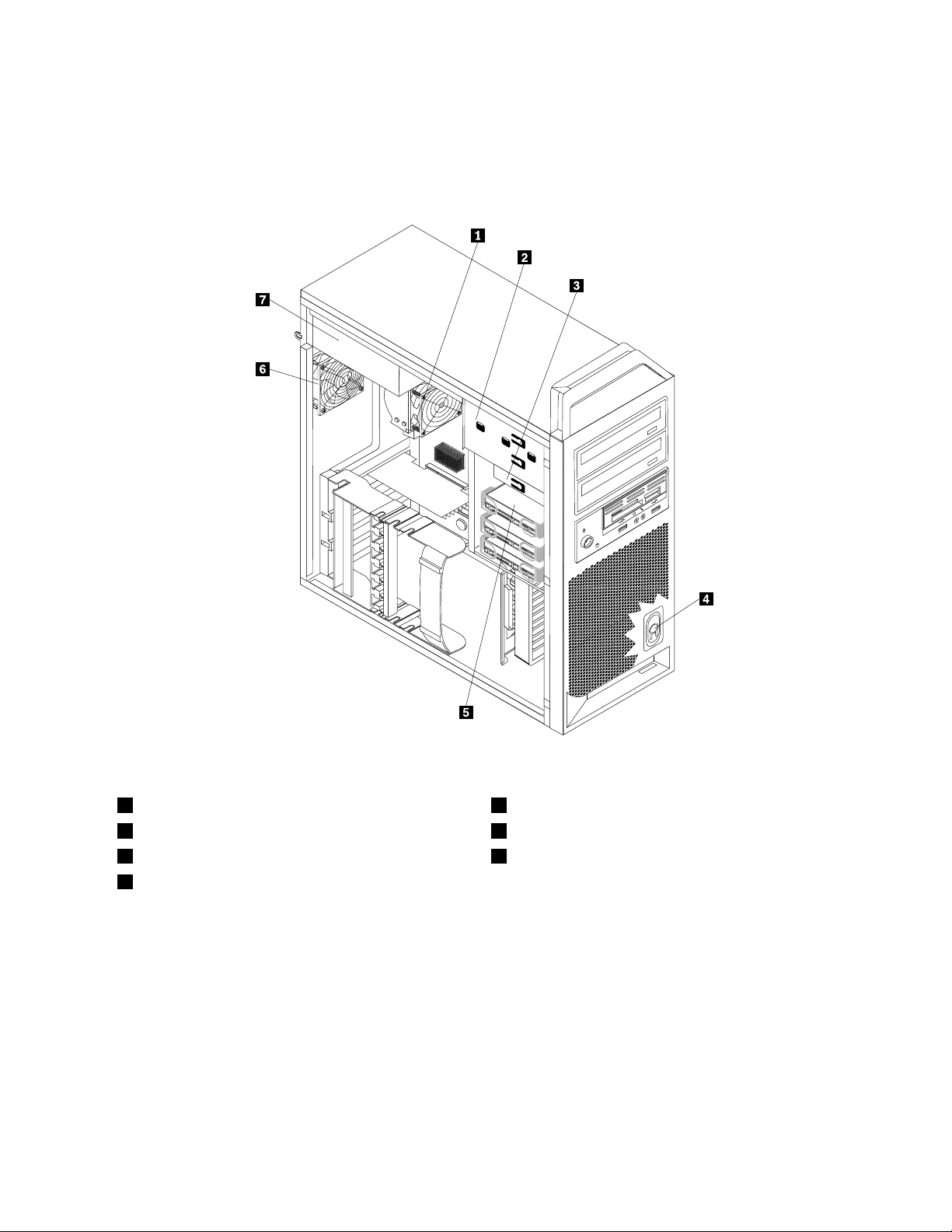
Locatinginternalcomponents
Toremovethecomputercover,see“Removingthecomputercover”onpage11.
Figure3“Componentlocations”onpage7
showsthelocationofthecomponentsinyourcomputer.
Figure3.Componentlocations
1Microprocessor,heatsink,andheatsinkfanassembly
2Opticaldrive
33.5-inchdiskettedriveorcardreader7Powersupplyassembly
4Internalspeaker
5Harddiskdrive
6Rearfanassembly
Chapter2.Overview7
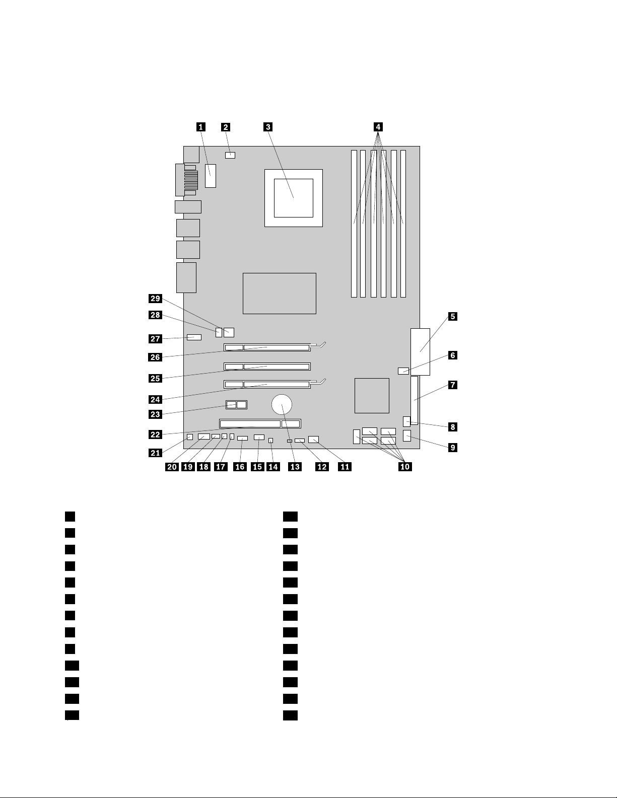
Identifyingpartsonthesystemboard
Figure4“Systemboardpartslocations”onpage8showsthelocationofthepartsonthesystemboard.
Figure4.Systemboardpartslocations
1Microprocessor12Vpowerconnector16Frontpanelconnector
2Microprocessorfanconnector
3Microprocessor18Thermalsensorconnector
4Memoryslots(6)19PS/2connector
524-pinsystempowerconnector20Frontaudioconnector
6Harddiskdrivefanassemblyconnector
7Diskettedriveconnector
8Cardreaderconnector23PCIExpressx1adaptercardslot
9FrontUSBconnector24PCIExpressx16graphicsadaptercardslot
10SA T Aconnectors(5)25PCIExpressx4adaptercardslot
11Adaptercardfanconnector
12SAS(SerialAttachedSCSI)LEDconnector27SecondCOMportconnector
13Battery
17Coverpresenceswitchconnector
21Internalspeakerconnector
22PCIadaptercardslot
26PCIExpressx16graphicsadaptercardslot
28Rearfanassemblyconnector
8ThinkStationHardwareInstallationandReplacementGuide

14ClearCMOS/Recoveryjumper
15AuxiliaryLEDconnector
29Auxiliary12Vpowerconnector
Chapter2.Overview9

10ThinkStationHardwareInstallationandReplacementGuide
Chapter3.Installingoptionsandreplacinghardware
Thischapterisanintroductiontothefeaturesandoptionsthatareavailableforyourcomputer.Youcan
expandthecapabilitiesofyourcomputerbyaddingmemorymodules,adaptercards,ordrives.When
installinganoption,usetheseinstructionsalongwiththeinstructionsthatcomewiththeoption.
Attention:Donotopenyourcomputerorattemptanyrepairbeforereadingandunderstandingthe“Importantsafety
information”intheThinkStationSafetyandWarrantyGuidethatcamewithyourcomputer.T oobtainacopyofthe
ThinkStationSafetyandWarrantyGuide,goto:
http://support.lenovo.com
Note:UseonlypartsprovidedbyLenovo.
Installingexternaloptions
Externalspeakers,aprinter,orascannercanbeconnectedtoyourcomputer.Forsomeexternaloptions,
youmustinstalladditionalsoftwareinadditiontomakingthephysicalconnection.Whenaddinganexternal
option,see“Locatingconnectorsontherearofyourcomputer”onpage5
connectorsonthefrontofyourcomputer”onpage4toidentifytherequiredconnector,andthenusethe
instructionsthatareincludedwiththeoptiontohelpyoumaketheconnectionandinstallanysoftware
ordevicedriversthatarerequiredfortheoption.
Installinginternaloptions
and“Locatingcontrolsand
Important:Read“Handlingstatic-sensitivedevices”onpage3beforeremovingthecomputercover.
Removingthecomputercover
CAUTION:
Turnoffthecomputerandwaitthreetoveminutestoletthecomputercoolbeforeremovingthe
computercover.
Toremovethecomputercover:
1.Removeanymediafromthedrivesandshutdownyouroperatingsystem.Turnoffallattacheddevices.
Turnoffthecomputer.
2.Unplugallpowercordsfromelectricaloutlets.
3.Disconnectthecablesattachedtothecomputer.Thisincludespowercords,input/output(I/O)cables,
andanyothercablesthatareconnectedtothecomputer.See“Locatingcontrolsandconnectorsonthe
frontofyourcomputer”onpage4and“Locatingconnectorsontherearofyourcomputer”onpage5.
4.Removeanylockingdevices,suchasacablelockorpadlockthatsecuresthecomputercover.Open
thekeylockifitisinthelockedposition.SeeChapter5“Securityfeatures”onpage49.
©CopyrightLenovo2009,2011
11
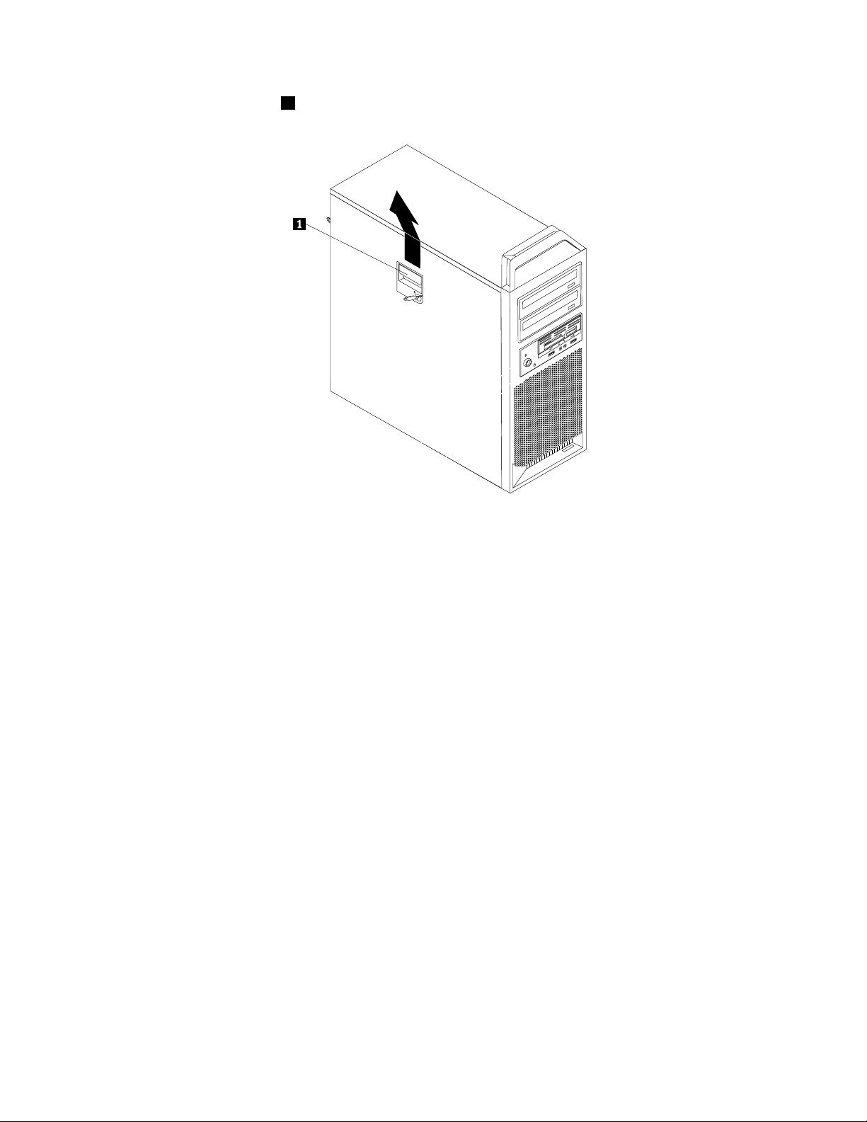
5.Disengagethecoverlatch1andremovethecover.Placethecoveronaatsurface.
Figure5.Removingthecomputercover
Removingthefrontbezel
Toremovethefrontbezel:
1.Removethecomputercover.See“Removingthecomputercover”onpage11.
12ThinkStationHardwareInstallationandReplacementGuide
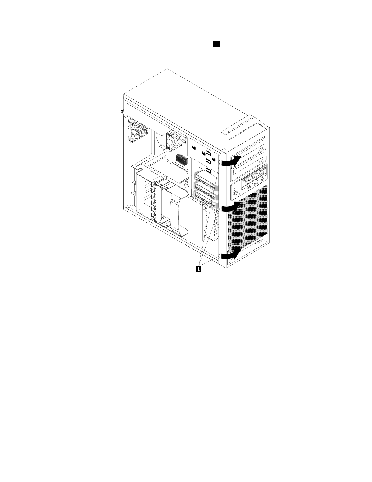
2.Removethefrontbezelbyreleasingthethreeplastictabs1ontheleftsideandpivotingthebezel
outward.
Figure6.Removingthefrontbezel
3.Laythefrontbezelonaatsurface.
4.Toreinstallthebezel,aligntheplastictabsontherightsideofthebezelwiththecorrespondingholesin
thechassis,thenpivotthebezelinwarduntilitsnapsintopositionontheleftside.
Accessingsystemboardcomponents
Toaccessthesystemboardcomponents:
1.Removethecomputercover.See“Removingthecomputercover”onpage11.
2.Unlatchandopentheadaptercardretainer.
3.Onsomemodels,youmightneedtoremovetheadaptercardstogaineasyaccesstosomeinternal
components.See“Replacinganadaptercard”onpage27.
Installingamemorymodule
YourcomputerhassixslotsforinstallingDDR3ECCUDIMMs(doubledatarate3errorcorrectioncode
unbuffereddualinlinememorymodules)thatprovideuptoamaximumof24GBofsystemmemory.
Wheninstallingmemorymodules,usethefollowingguidelines:
•Use1.8V ,240-pinDDR3ECCUDIMMs.
Chapter3.Installingoptionsandreplacinghardware13
•Use1GB,2GBor4GBmemorymodulesinanycombinationuptoamaximumof24GB.
•Installmemorymodulesintothebluecolormemoryslotsrst.
Note:OnlyDDR3ECCUDIMMscanbeused.
Toinstallamemorymodule:
1.Removethecomputercover.See“Removingthecomputercover”onpage11.
Note:Forthisprocedure,ithelpstolaythecomputeronitsside.
2.Locatethememoryslots.See“Identifyingpartsonthesystemboard”onpage8.
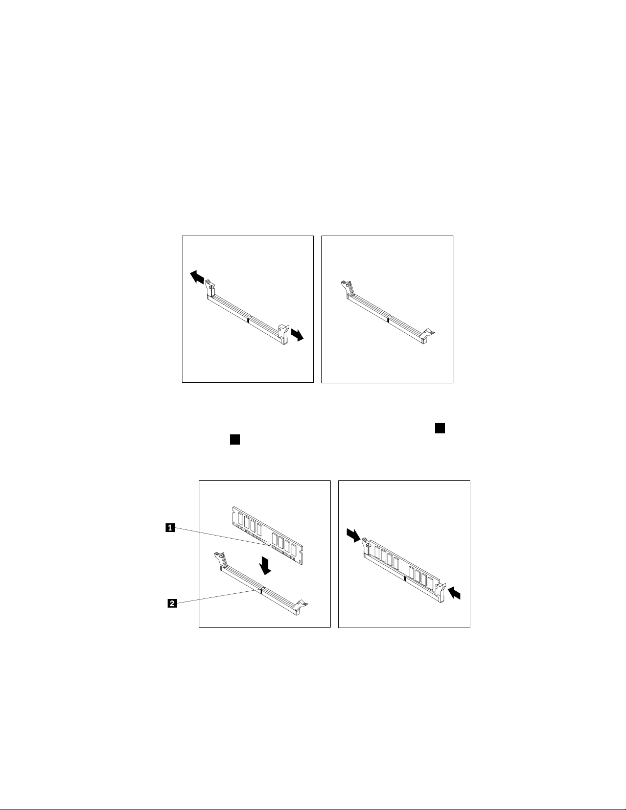
3.Opentheretainingclipsasshown.
Figure7.Openingtheretainingclips
4.Positionthenewmemorymoduleoverthememoryslot.Makesurethenotch1onthememorymodule
alignscorrectlywiththeslotkey
theslotuntiltheretainingclipsclose.
Figure8.Installingthememorymodule
5.GotoChapter4“Completingthepartsreplacement”onpage47.
2onthesystemboard.Pushthememorymodulestraightdowninto
Installinganadaptercard
Thissectionprovidesinformationandinstructionsforinstallinganadaptercard.
14ThinkStationHardwareInstallationandReplacementGuide
Loading...