


 Loading...
M920s User Guide and Hardware
Maintenance Manual
Energy Star Machine Types: 10SJ, 10SK, 10SL, 10TN, 10U2 and
10U3
Note: Before using this information and the product it supports, be sure to read and understand the
Important Product Information Guide and Appendix A “Notices” on page 65.
First Edition (June 2018)
© Copyright Lenovo 2018.
LIMITED AND RESTRICTED RIGHTS NOTICE: If data or software is delivered pursuant to a General Services Administration “GSA” contract, use, reproduction, or disclosure is subject to restrictions set forth in Contract No. GS- 35F-05925.

Contents
Chapter 1. Overview. . . . . . . . . . . 1
Front view . . . . . . . . . . . . . . . . . . 1
Rear view . . . . . . . . . . . . . . . . . . 3
System board . . . . . . . . |
. . |
. |
. . . . |
. |
5 |
Machine type and model label . . |
. . |
. |
. . . . |
. |
6 |
Chapter 2. Specifications . . . . . . . . 7 Chapter 3. Computer locks . . . . . . . 9
Enabling or disabling the E-lock . . . . . . . . |
. 9 |
Locking the computer cover . . . . . . . . . . |
10 |
Attaching a Kensington-style cable lock . . . . . |
10 |
Attaching a cable lock . . . . . . . . . . . . |
11 |
Chapter 4. Replacing hardware . . . . |
13 |
Before replacing hardware . . . . . . . . . . |
13 |
Knowing FRUs (including CRUs) . . . . . . . . |
13 |
Locating FRUs (including CRUs) . . . . . . . . |
14 |
Replacing the power cord . . . . . . . . . . . |
16 |
Replacing the external options . . . . . . . . . |
17 |
Removing the computer cover . . . . . . . . . |
19 |
Replacing the front bezel . . . . . . . . . . . |
20 |
Replacing the optical drive . . . . . . . . . . |
21 |
Pivoting the drive bay assembly upward and |
|
downward . . . . . . . . . . . . . . . . . |
23 |
Replacing the internal speaker . . . . . . . . . |
24 |
Replacing the illuminated red dot . . . . . . . . |
27 |
Replacing the thermal sensor . . . . . . . . . |
28 |
Replacing the front I/O options . . . . . . . . . |
31 |
Replacing the storage drive . . . . . . . . . . |
34 |
Replacing the memory module . . . . . . . . . |
40 |
Replacing the heat sink and fan assembly . . . . |
41 |
Replacing the microprocessor . . . . . . . . . |
43 |
Replacing a PCI Express card . . . . . . . . . |
45 |
Replacing the E-lock . . . . . . . . . . . . . |
46 |
Replacing the cover presence switch . . . . . . |
47 |
Replacing the Wi-Fi card . . . . . . . . . . . |
48 |
Replacing the Wi-Fi antennas . . . . . . . . . |
52 |
Replacing the coin-cell battery . . . . . . . . . |
54 |
Replacing the M.2 storage drive . . . . . . . . |
56 |
Replacing the M.2 storage drive bracket . . . . . |
58 |
Replacing the power supply assembly . . . . . . |
59 |
Replacing the system board . . . . . . . . . . |
61 |
Completing the parts replacement . . . . . . . |
62 |
Appendix A. Notices. . . . . . . . . . 65 |
|
Appendix B. Trademarks . . . . . . . |
67 |
© Copyright Lenovo 2018 |
i |
ii M920s User Guide and Hardware Maintenance Manual
Chapter 1. Overview
This chapter provides basic information to help you get familiar with your computer.
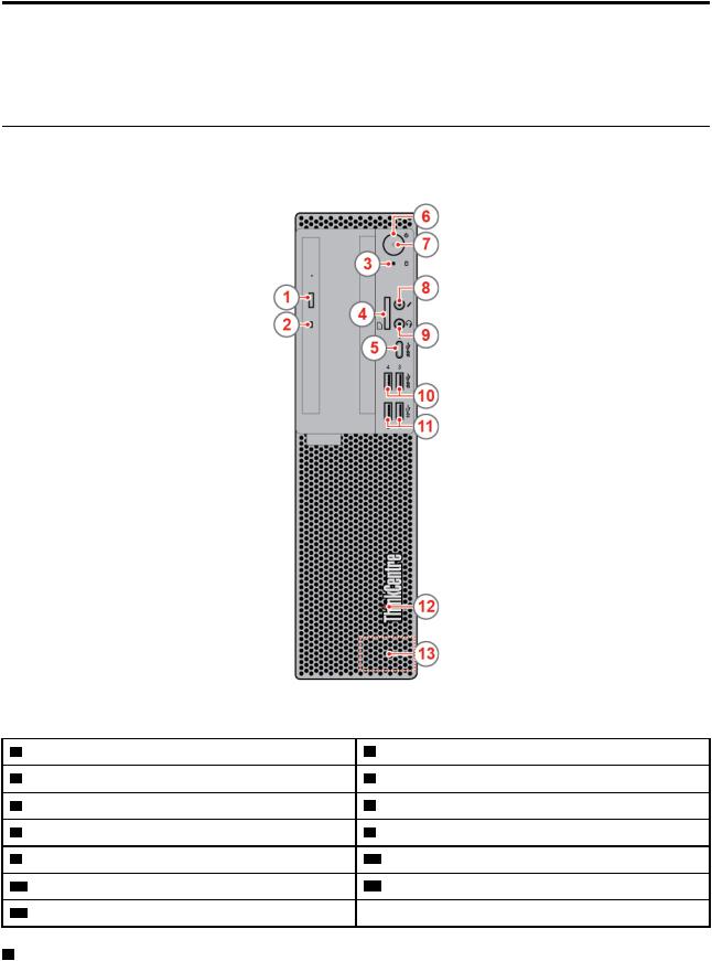
Front view
Note: Your computer model might look slightly different from the illustration.
Figure 1. Front view |
|
|
|
1 |
Optical drive eject/close button (optional) |
2 |
Optical drive status indicator (optional) |
3 |
Storage drive activity indicator |
4 |
Card reader (optional) |
5 |
USB 3.1 Gen 1 Type-C connector |
6 |
Power button |
7 |
Power indicator |
8 |
Microphone connector |
9 |
Headset connector |
10 USB 3.1 Gen 1 connectors (2) |
|
11 USB 3.1 Gen 2 connectors (2) |
12 Illuminated red dot |
||
13 Internal speaker |
|
|
|
1 Optical drive eject/close button
© Copyright Lenovo 2018 |
1 |

Used to eject the tray of the optical drive. After you insert a disc into the tray, press the eject/close button to close the tray.
2 Optical drive activity indicator
This indicator is on when the optical drive is in use.
3 Storage drive activity indicator
This indicator is on when the storage drive is in use.
4 Card reader slot
Used to read data from a supported memory card.
5 USB 3.1 Gen 1 Type-C connector
Used to connect a USB-compatible device, such as a USB keyboard, mouse, scanner, printer, or personal digital assistant (PDA). For optimal data transfer, connect a USB 3.1 Gen 1 device to a USB 3.1 Gen 1 connector instead of a USB 2.0 connector.
6 Power button
Used to turn on your computer. When you cannot shut down the computer from the operating system, press and hold the power button for four or more seconds to turn off the computer.
7 Power indicator
This indicator is on when the computer is on.
8 Microphone connector
Used to connect a microphone to your computer. You can use the microphone to record sounds or interact with the computer using speech-recognition software.
9 Headset connector
Used to connect headset to your computer.
10 USB 3.1 Gen 1 connectors
Used to connect a USB-compatible device. For optimal data transfer, connect a USB 3.1 Gen 1 device to a USB 3.1 Gen 2 or USB 3.1 Gen 1 connector instead of a USB 2.0 connector.
11 USB 3.1 Gen 2 connectors
Used to connect a USB-compatible device. For optimal data transfer, connect a USB 3.1 Gen 2 device to a USB 3.1 Gen 2 connector instead of a USB 3.1 Gen 1 or USB 2.0 connector.
12 Illuminated red dot
This indicator is on when the computer is on.
13 Internal speaker
Used to listen to the sounds from your computer without using a headset or headphones.
2 M920s User Guide and Hardware Maintenance Manual
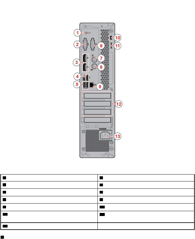
Rear view
Note: Your computer model might look slightly different from the illustration.
Figure 2. Rear view |
|
|
|
1 |
Audio line-out connector |
2 |
VGA-out connector |
3 |
DisplayPort® 1.2 out connector(2) |
4 |
USB 3.1 Gen 1 connector |
5 |
USB 3.1 Gen 1 connectors (3) |
6 |
Serial connector |
7 |
PS/2 mouse connector (optional) |
8 |
PS/2 keyboard connector (optional) |
9 |
Ethernet connector |
10 Security-lock slot |
|
11 Padlock loop |
12 PCI-Express card area (different cards provide |
||
|
|
different connectors) |
|
13 Power cord connector
1 Audio line-out connector
Used to send audio signals from the computer to external devices, such as powered stereo speakers, headphones, or multimedia keyboards. To connect a stereo system or other external recording device, connect a cable between the audio line-in connector of the device and the audio line-out connector of the computer.
Chapter 1. Overview 3

Note: If your computer has both an audio line-out connector and a headset or headphone connector, always use the headset connector or headphone connector for earphones, headphones, or a headset. The headphone connector does not support headset microphones.
2 VGA-out connector
Used to send video signals from the computer to another video device, such as a monitor.
3 DisplayPort 1.2 out connector
Used to send audio and video signals from the computer to another audio or video device, such as a highperformance monitor.
4 USB 3.1 Gen 1 connector
Used to connect a USB-compatible device. For optimal data transfer, connect a USB 3.1 Gen 1 device to a USB 3.1 Gen 2 or USB 3.1 Gen 1 connector instead of a USB 2.0 connector. This connector supports the smart power on feature that enables you to turn on the computer or wake it up from S4 hibernation mode by pressing Alt+P on the keyboard. You can enable or disable the smart power on feature from the Setup Utility program. For detailed information, see the Important Product Information Guide
5 USB 3.1 Gen 1 connectors
Used to connect a USB-compatible device. For optimal data transfer, connect a USB 3.1 Gen 1 device to a USB 3.1 Gen 2 or USB 3.1 Gen 1 connector instead of a USB 2.0 connector.
6 Serial connector
Used to connect an external modem, a serial printer, or other devices that use a serial connector.
7 PS/2 mouse connector
Used to connect a mouse, a trackball, or other pointing devices that use a PS/2 mouse connector.
8 PS/2 keyboard connector
Used to connect a keyboard that uses a Personal System/2 (PS/2) keyboard connector.
9 Ethernet connector
Used to connect an Ethernet cable for network access.
10 Security-lock slot
Used to secure a Kensington-style cable lock.
11 Padlock loop
Used to secure a padlock.
12 PCI-Express card area
To improve the operating performance of the computer, you can connect PCI-Express cards into this area. Depending on the computer model, the connectors in this area vary.
13 Power cord connector
4 M920s User Guide and Hardware Maintenance Manual

Used to connect the power cord to your computer for power supply.
System board
Note: See “Front view” on page 1 and “Rear view” on page 3 for additional component descriptions.
Figure 3. System board |
|
|
|
||
1 |
4-pin power connector |
2 |
Microprocessor fan connector |
||
3 |
Memory slot (DIMM1) |
4 |
Memory slot (DIMM2) |
||
5 |
Memory slot (DIMM3) |
6 |
Memory slot (DIMM4) |
||
7 |
Power button board connector |
8 |
Internal speaker connector |
||
9 |
10-pin power connector |
10 |
SATA power connector |
||
11 |
SATA power connector |
12 |
Auxiliary fan connector |
||
13 |
SATA 3.0 connector |
14 |
SATA 3.0 connector |
||
15 |
SATA 3.0 connector |
16 |
Clear CMOS jumper |
||
17 |
SATA 3.0 connector |
18 |
M.2 storage drive slot |
||
19 |
M.2 Wi-Fi card slot |
20 |
Thermal sensor connector |
||
21 |
Illuminated red dot connector |
22 |
Front USB 2.0 connector |
||
23 |
Front USB 2.0 connector |
24 |
Serial connector (optional) |
||
25 |
Thunderbolt connector |
26 |
PCI Express card slot (physical link width x16; |
||
|
|
|
negotiable link width x4, x1) |
||
27 |
PCI Express x1 card slot |
28 |
PCI Express x16 graphics card slot |
||
Chapter 1. Overview 5
29 |
E-lock connector |
30 |
System fan connector |
31 |
Cover presence switch |
32 |
Coin-cell battery |
33 |
Microprocessor socket |
34 |
PS/2 keyboard and mouse connector |
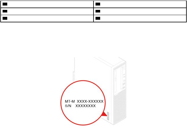
Machine type and model label
The machine type and model label identifies the computer. When you contact Lenovo for help, the machine type and model information helps support technicians to identify the computer and provide faster service. The machine type and model label is attached on the side of the computer as shown.
Figure 4. Machine type and model label
6 M920s User Guide and Hardware Maintenance Manual
Chapter 2. Specifications
Power supply
•180 watt automatic voltage-sensing power supply
•210 watt automatic voltage-sensing power supply
•260 watt automatic voltage-sensing power supply
Storage drives
Up to two SATA storage drives and one M.2 storage drive
Video features
•The integrated graphics card supports the following:
–DisplayPort-out connector
–VGA-out connector
•The optional discrete graphics card provides an enhanced video experience and extended capabilities.
Audio features
•The integrated audio card supports the following:
–Audio line-out connector
–Headset connector
–Internal speaker
–Microphone connector
•The optional discrete audio card provides an enhanced audio experience and extended capabilities.
Input/Output (I/O) features
•Audio connectors (audio line-out connector, headset connector, and microphone connector)
•Card reader slot (optional)
•Display connectors (DisplayPort-out connector and VGA-out connector)
•Ethernet connector
•PS/2 keyboard connector (optional)
•PS/2 mouse connector (optional)
•Serial connector
•USB connectors
Expansion
•Card reader (optional)
•Memory slot
•Optical drive (optional)
•PCI Express card slot (physical link width x16; negotiable link width x4, x1)
•PCI Express x1 card slot
•PCI Express x16 graphics card slot
•Storage drive bay
© Copyright Lenovo 2018 |
7 |
Network features
•Ethernet LAN
•Wireless LAN (optional)
•Bluetooth (optional)
Physical dimensions
•Width: 92.5 mm (3.6 inches)
•Height: 343.5 mm (13.5 inches)
•Depth: 290.5 mm (11.4 inches)
Weight (without the package)
Maximum configuration as shipped: 6.0 kg (13.2 lb)
8 M920s User Guide and Hardware Maintenance Manual
Chapter 3. Computer locks
This chapter provides instructions on how to lock your computer with the locking devices to keep your computer safe.
Enabling or disabling the E-lock
Your computer may have a security lock solution installed to protect the computer from unauthorized tampering of the internal components. Using the E-Lock, you can mechanically lock or unlock the computer cover.
To enable or disable the E-Lock, do the following:
1.Turn on or restart the computer.
2.Before Windows starts up, repeatedly press and release the F1 or Fn+F1 key until the Setup Utility program opens.
3.Click Security Electronic Lock to enable or disable the E-lock.
4.Press F10 or Fn+F10 to save the changes and reboot the computer.
Note: Changes do not take effect until the setting is saved and the system is rebooted.
Figure 5. Enabling or disabling the E-lock
© Copyright Lenovo 2018 |
9 |
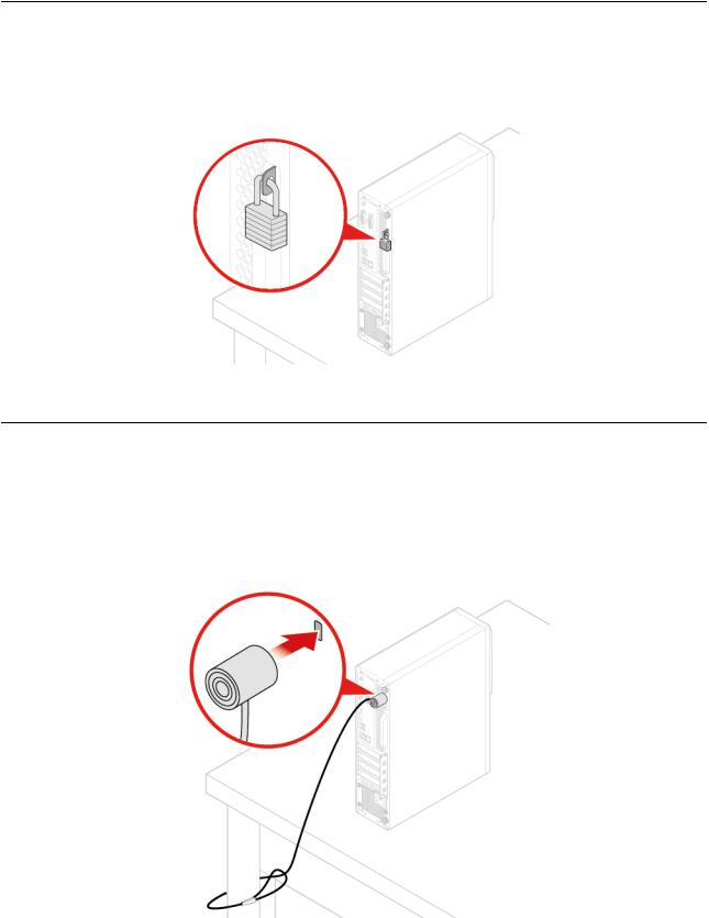
Locking the computer cover
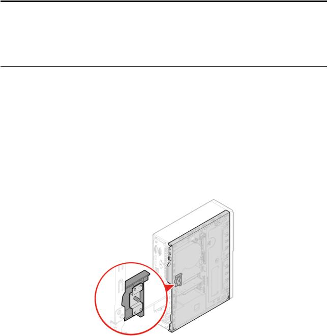
Locking the computer cover helps prevent unauthorized access to the inside of your computer. Your computer features a padlock loop so that the computer cover cannot be removed when a padlock is installed.
Figure 6. Locking the computer cover
Attaching a Kensington-style cable lock
You can use a Kensington-style cable lock to secure your computer to a desk, table, or other nonpermanent fixture. The cable lock connects to the security-lock slot at the rear of your computer. Depending on the type selected, the cable lock can be operated with a key or combination. The cable lock also locks the buttons used to open the computer cover. This is the same type of lock used with many notebook computers. You can order such a cable lock directly from Lenovo by searching for Kensington at: http://www.lenovo.com/support
Figure 7. Attaching a Kensington-style cable lock
10 M920s User Guide and Hardware Maintenance Manual
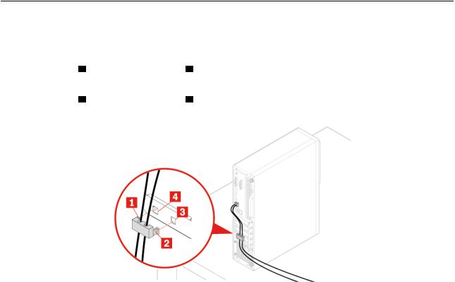
Attaching a cable lock
A cable lock can be used to secure devices, such as the keyboard and the mouse, by locking the device cables to the computer. The cable lock connects to the cable-lock slots on the rear of the computer. To install a cable lock, do the following:
1.Insert the clip 1 into the cable-lock slot 4 .
2.Pull the cables you want to lock through the dents in the cable lock.
3.Press the clip 2 into the cable-lock slot 3 until it snaps into position.
Figure 8. Attaching a cable lock
Chapter 3. Computer locks 11
12 M920s User Guide and Hardware Maintenance Manual

Chapter 4. Replacing hardware
This chapter provides instructions on how to replace hardware for your computer.
Before replacing hardware
Attention: Do not open your computer or attempt any repairs before reading this section and the Important Product Information Guide .
Notes before replacing hardware
•Use computer components provided only by Lenovo.
•When installing or replacing an option, use the appropriate instructions explained in this manual along with the instructions that come with the option.
•In most areas of the world, Lenovo requires the return of defective CRUs. Information about this will come with the CRU or will come a few days after the CRU arrives.
Handling static-sensitive devices
Do not open the static-protective package containing the new part until the defective part has been removed and you are ready to install the new part. Static electricity, although harmless to you, can seriously damage computer components and options.
When you handle options and other computer components, take these precautions to avoid static-electricity damage:
•Limit your movement. Movement can cause static electricity to build up around you.
•Always handle options and other computer components carefully. Handle PCI/PCIe cards, memory modules, system boards, and microprocessors by the edges. Never touch any exposed circuitry.
•Prevent others from touching the options and other computer components.
•Touch the static-protective package containing the part to a metal expansion-slot cover or other unpainted metal surface on the computer for at least two seconds. This reduces static electricity from the package and your body before you install or replace a new part.
•When possible, remove the new part from the static-protective package, and install it directly in the computer without setting the part down. When this is not possible, place the static-protective package on a smooth, level surface and place the part on the package.
•Do not place the part on the computer cover or other metal surface.
Knowing FRUs (including CRUs)
•Field Replaceable Units (FRUs) are computer parts that a trained technician can upgrade or replace. FRUs include all CRUs. For detailed FRU information, such as the FRU part numbers and supported computer models, go to:
http://www.lenovo.com/serviceparts-lookup
•Customer Replaceable Units (CRUs) are computer parts that a user can upgrade or replace.
–Self-service CRUs: You can install self-service CRUs easily. These CRUs might be stand-alone, latched, or secured by up to two screws. Examples of self-service CRUs include the keyboard, mouse, any USB device. You are responsible for replacing all self-service CRUs.
–Optional-service CRUs: Handling optional-service CRUs requires some technical skills and simple tools (such as a screwdriver). These CRUs are isolated parts within the computer. They are usually
© Copyright Lenovo 2018 |
13 |

concealed by an access panel that is secured by more than two screws. You must remove the screws and panel to access the specific CRU. Optional-service CRUs can be removed and installed by users or, during the warranty period, by a Lenovo service technician.
Before replacing FRUs
Before replacing any FRU, read the following:
•Only certified and trained personnel can service the computer.
•Before replacing an FRU, read the entire section about replacing the part.
•Be extremely careful during writing operations such as copying, saving, or formatting.
The sequence of the drives in the computer that you are servicing might have been altered. If you select an incorrect drive, data or programs might be overwritten.
•Replace an FRU only with another FRU of the correct model.
When you replace an FRU, ensure that the model of the machine and the FRU part number are correct.
•An FRU should not be replaced because of a single, unreproducible failure.
Single failures can occur for a variety of reasons that have nothing to do with a hardware defect, such as cosmic radiation, electrostatic discharge, or software errors. Consider replacing an FRU only when a problem recurs. If you suspect that an FRU is defective, clear the error log and run the test again. If the error does not recur, do not replace the FRU.
•Only replace a defective FRU.
Locating FRUs (including CRUs)
Notes:
•Some of the following components are optional.
•To replace a component that is not in the list below, contact a Lenovo service technician. For a list of Lenovo Support phone numbers, go to:
http://www.lenovo.com/support/phone
14 M920s User Guide and Hardware Maintenance Manual

Figure 9. Locating FRUs (including CRUs) |
|
|
|
|
||
Self-service CRUs |
Optional-service CRUs |
Non-CRUs |
||||
1 |
Computer cover |
7 |
Wi-Fi card |
2 |
Heat sink and fan assembly |
|
4 |
Memory module |
8 |
Wi-Fi card shield |
3 |
Microprocessor |
|
6 |
Coin-cell battery |
34 |
Power supply assembly |
5 |
System board |
|
10 |
M.2 storage drive |
36 |
E-lock |
9 |
Cover presence switch |
|
11 |
M.2 storage drive bracket |
|
|
14 Power button |
||
12 |
Secondary storage drive bracket |
|
|
15 Card reader |
||
13 |
Secondary storage drive (a 2.5- |
|
|
16 Front I/O bracket |
||
inch storage drive)
Chapter 4. Replacing hardware 15
Self-service CRUs |
Optional-service CRUs |
Non-CRUs |
||
18 |
Optical drive bracket |
|
17 |
Optical drive cable |
19 |
Optical drive |
|
28 |
Storage drive cable |
20 |
Front bezel |
|
29 |
Illuminated red dot |
21 |
Dust shield |
|
30 |
Thermal sensor |
22 |
Keyboard |
|
31 |
Internal speaker |
23 |
Mouse |
|
33 |
Chassis |
24 |
Power cord |
|
35 |
Wi-Fi antennas |
25 |
Primary storage drive (a 2.5-inch |
|
|
|
or 3.5-inch storage drive) |
|
|
|
|
26 |
Primary storage drive bracket |
|
|
|
27 |
Storage drive converter |
|
|
|
32 |
Vertical stand |
|
|
|
37 |
PCI Express card |
|
|
|
Replacing the power cord
Attention: Do not open your computer or attempt any repairs before reading the Important Product Information Guide .
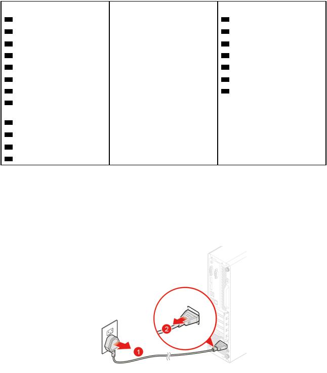
1.Remove any media from the drives and turn off all connected devices and the computer. Disconnect all power cords from electrical outlets and disconnect all cables from the computer.
2.Replace the power cord.
Figure 10. Removing the power cord
16 M920s User Guide and Hardware Maintenance Manual
Figure 11. Installing the power cord
Replacing the external options
Attention: Do not open your computer or attempt any repairs before reading the Important Product Information Guide .
1.Remove any media from the drives and turn off all connected devices and the computer. Disconnect all power cords from electrical outlets and disconnect all cables from the computer.
2.Refer to the following to replace external options.
• Vertical stand
Figure 12. Removing the vertical stand
Chapter 4. Replacing hardware 17
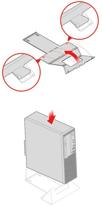
Figure 13. Assembling the vertical stand
Figure 14. Installing the vertical stand
• Dust shield
18 M920s User Guide and Hardware Maintenance Manual
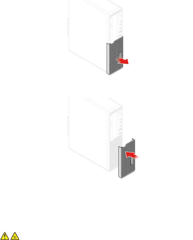
Figure 15. Removing the dust shield
Figure 16. Installing the dust shield
3. Reconnect all cables.
Removing the computer cover
Attention: Do not open your computer or attempt any repairs before reading the Important Product
Information Guide |
. |
CAUTION: |
|
Before you open the computer cover, turn off the computer and wait several minutes until the computer is cool.
1.Remove any media from the drives and turn off all connected devices and the computer. Disconnect all power cords from electrical outlets and disconnect all cables from the computer.
Chapter 4. Replacing hardware 19
Loading...