


 Loading...
Lenovo Storage S3200/S2200
Setup Guide
For firmware release GL210 or later
Abstract
This document describes initial hardware setup for Lenovo Storage S3200/S2200 controller enclosures, and is intended for use by storage system administrators familiar with servers and computer networks, network administration, storage system installation and configuration, storage area network management, and relevant protocols.
Part Number: 00WE606
First Edition, May 2015
Copyright Lenovo 2015.
LIMITED AND RESTRICTED RIGHTS NOTICE: If data or software is delivered pursuant a General Services Administration “GSA” contract, use, reproduction, or disclosure is subject to restrictions set forth in Contract No. GS-35F-05925.
Lenovo, the Lenovo logo, BladeCenter, Flex System, NeXtScale System, and System x are trademarks of Lenovo in the United States, other countries, or both.
The material in this document is for information only and is subject to change without notice. While reasonable efforts have been made in the preparation of this document to assure its accuracy, changes in the product design can be made without reservation and without notification to its users.

Contents
About this guide. . . . . . . . . . . . . . . . . . . . . . . . . . . . . . . . . . . . . . . . . . . . . . . . . . . . . . . 9
Overview. . . . . . . . . . . . . . . . . . . . . . . . . . . . . . . . . . . . . . . . . . . . . . . . . . . . . . . . . . . . . . . . . . . . . . 9 Storage S3200/S2200 enclosure user interfaces . . . . . . . . . . . . . . . . . . . . . . . . . . . . . . . . . . . . . . . 9 CNC ports used for host connection. . . . . . . . . . . . . . . . . . . . . . . . . . . . . . . . . . . . . . . . . . . . . . . . 10 HD mini-SAS ports used for host connection . . . . . . . . . . . . . . . . . . . . . . . . . . . . . . . . . . . . . . . . . . 10 Intended audience . . . . . . . . . . . . . . . . . . . . . . . . . . . . . . . . . . . . . . . . . . . . . . . . . . . . . . . . . . . . . . 10 Prerequisites. . . . . . . . . . . . . . . . . . . . . . . . . . . . . . . . . . . . . . . . . . . . . . . . . . . . . . . . . . . . . . . . . . . 10 Related documentation . . . . . . . . . . . . . . . . . . . . . . . . . . . . . . . . . . . . . . . . . . . . . . . . . . . . . . . . . . . 11 Document conventions and symbols . . . . . . . . . . . . . . . . . . . . . . . . . . . . . . . . . . . . . . . . . . . . . . . . . . 12
1 Components . . . . . . . . . . . . . . . . . . . . . . . . . . . . . . . . . . . . . . . . . . . . . . . . . . . . . . 13
Front panel components . . . . . . . . . . . . . . . . . . . . . . . . . . . . . . . . . . . . . . . . . . . . . . . . . . . . . . . . . . 13 24-drive enclosure front panel components . . . . . . . . . . . . . . . . . . . . . . . . . . . . . . . . . . . . . . . . . . . 13 12-drive enclosure front panel components . . . . . . . . . . . . . . . . . . . . . . . . . . . . . . . . . . . . . . . . . . . 14 Disk drives used in S3200/S2200 enclosures . . . . . . . . . . . . . . . . . . . . . . . . . . . . . . . . . . . . . . . . . 15 Controller enclosure — rear panel layout. . . . . . . . . . . . . . . . . . . . . . . . . . . . . . . . . . . . . . . . . . . . . . . 15 S3200 CNC controller module — rear panel components . . . . . . . . . . . . . . . . . . . . . . . . . . . . . . . . 16 S3200 SAS controller module — rear panel components . . . . . . . . . . . . . . . . . . . . . . . . . . . . . . . . . 17 S2200 CNC controller module — rear panel components . . . . . . . . . . . . . . . . . . . . . . . . . . . . . . . . 17 S2200 SAS controller module — rear panel components . . . . . . . . . . . . . . . . . . . . . . . . . . . . . . . . . 18 E1024/E1012 drive enclosure rear panel components . . . . . . . . . . . . . . . . . . . . . . . . . . . . . . . . . . . . . 19 Component installation and replacement . . . . . . . . . . . . . . . . . . . . . . . . . . . . . . . . . . . . . . . . . . . . . . . 19 Cache . . . . . . . . . . . . . . . . . . . . . . . . . . . . . . . . . . . . . . . . . . . . . . . . . . . . . . . . . . . . . . . . . . . . . . . 19 CompactFlash . . . . . . . . . . . . . . . . . . . . . . . . . . . . . . . . . . . . . . . . . . . . . . . . . . . . . . . . . . . . . . . . . 20 Supercapacitor pack . . . . . . . . . . . . . . . . . . . . . . . . . . . . . . . . . . . . . . . . . . . . . . . . . . . . . . . . . . . . . 20
2 Installing the enclosures. . . . . . . . . . . . . . . . . . . . . . . . . . . . . . . . . . . . . . . . . . . . . . . 21
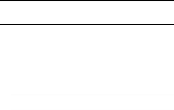
Installation checklist . . . . . . . . . . . . . . . . . . . . . . . . . . . . . . . . . . . . . . . . . . . . . . . . . . . . . . . . . . . . . 21 FDE considerations. . . . . . . . . . . . . . . . . . . . . . . . . . . . . . . . . . . . . . . . . . . . . . . . . . . . . . . . . . . . 21 Connecting the controller enclosure and drive enclosures. . . . . . . . . . . . . . . . . . . . . . . . . . . . . . . . . . . . 22 Connecting the S3200/S2200 controller to the 2U12 drive enclosure . . . . . . . . . . . . . . . . . . . . . . . . 23 Connecting the S3200/S2200 controller to the 2U24 drive enclosure . . . . . . . . . . . . . . . . . . . . . . . . 23 Connecting the S3200/S2200 controller to mixed model drive enclosures . . . . . . . . . . . . . . . . . . . . . 23 Cable requirements for storage enclosures . . . . . . . . . . . . . . . . . . . . . . . . . . . . . . . . . . . . . . . . . . . 23 Summary of drive enclosure cabling illustrations . . . . . . . . . . . . . . . . . . . . . . . . . . . . . . . . . . . . . 25 Testing enclosure connections. . . . . . . . . . . . . . . . . . . . . . . . . . . . . . . . . . . . . . . . . . . . . . . . . . . . . . . 28 Powering on/powering off. . . . . . . . . . . . . . . . . . . . . . . . . . . . . . . . . . . . . . . . . . . . . . . . . . . . . . . . . 28 AC PSU . . . . . . . . . . . . . . . . . . . . . . . . . . . . . . . . . . . . . . . . . . . . . . . . . . . . . . . . . . . . . . . . . . . 28
3 Connecting hosts . . . . . . . . . . . . . . . . . . . . . . . . . . . . . . . . . . . . . . . . . . . . . . . . . . . 30
Host system requirements. . . . . . . . . . . . . . . . . . . . . . . . . . . . . . . . . . . . . . . . . . . . . . . . . . . . . . . . . . 30 Cabling considerations . . . . . . . . . . . . . . . . . . . . . . . . . . . . . . . . . . . . . . . . . . . . . . . . . . . . . . . . . . . 30 Connecting the enclosure to hosts . . . . . . . . . . . . . . . . . . . . . . . . . . . . . . . . . . . . . . . . . . . . . . . . . . . . 30 CNC technology . . . . . . . . . . . . . . . . . . . . . . . . . . . . . . . . . . . . . . . . . . . . . . . . . . . . . . . . . . . . . 30 Fibre Channel protocol . . . . . . . . . . . . . . . . . . . . . . . . . . . . . . . . . . . . . . . . . . . . . . . . . . . . . . 31 10GbE iSCSI protocol . . . . . . . . . . . . . . . . . . . . . . . . . . . . . . . . . . . . . . . . . . . . . . . . . . . . . . 31 1 Gb iSCSI protocol . . . . . . . . . . . . . . . . . . . . . . . . . . . . . . . . . . . . . . . . . . . . . . . . . . . . . . . . 31
HD mini-SAS technology . . . . . . . . . . . . . . . . . . . . . . . . . . . . . . . . . . . . . . . . . . . . . . . . . . . . . . . . 32 12 Gb mini-SAS ports . . . . . . . . . . . . . . . . . . . . . . . . . . . . . . . . . . . . . . . . . . . . . . . . . . . . . . . 32 Connecting direct attach configurations . . . . . . . . . . . . . . . . . . . . . . . . . . . . . . . . . . . . . . . . . . . . . 32 Fibre Channel host connection . . . . . . . . . . . . . . . . . . . . . . . . . . . . . . . . . . . . . . . . . . . . . . . . . 32 10GbE iSCSI host connection. . . . . . . . . . . . . . . . . . . . . . . . . . . . . . . . . . . . . . . . . . . . . . . . . . 32 1 Gb iSCSI host connection . . . . . . . . . . . . . . . . . . . . . . . . . . . . . . . . . . . . . . . . . . . . . . . . . . . 32 HD mini-SAS host connection . . . . . . . . . . . . . . . . . . . . . . . . . . . . . . . . . . . . . . . . . . . . . . . . . . 33
Lenovo Storage S3200/S2200 Setup Guide |
3 |
Single-controller configurations . . . . . . . . . . . . . . . . . . . . . . . . . . . . . . . . . . . . . . . . . . . . . . . . . 33 Dual-controller configurations . . . . . . . . . . . . . . . . . . . . . . . . . . . . . . . . . . . . . . . . . . . . . . . . . . 35 Connecting switch attach configurations . . . . . . . . . . . . . . . . . . . . . . . . . . . . . . . . . . . . . . . . . . . . . 38 Dual-controller configuration. . . . . . . . . . . . . . . . . . . . . . . . . . . . . . . . . . . . . . . . . . . . . . . . . . . 38 Connecting a management host on the network . . . . . . . . . . . . . . . . . . . . . . . . . . . . . . . . . . . . . . . . . . 40 Updating firmware . . . . . . . . . . . . . . . . . . . . . . . . . . . . . . . . . . . . . . . . . . . . . . . . . . . . . . . . . . . . . . 40 Obtaining IP values . . . . . . . . . . . . . . . . . . . . . . . . . . . . . . . . . . . . . . . . . . . . . . . . . . . . . . . . . . . . . 41 Setting network port IP addresses using DHCP. . . . . . . . . . . . . . . . . . . . . . . . . . . . . . . . . . . . . . . . . 41 Setting network port IP addresses using the CLI port and cable . . . . . . . . . . . . . . . . . . . . . . . . . . . . . 41 Change the CNC port mode. . . . . . . . . . . . . . . . . . . . . . . . . . . . . . . . . . . . . . . . . . . . . . . . . . . . . 44 Set CNC port mode to iSCSI . . . . . . . . . . . . . . . . . . . . . . . . . . . . . . . . . . . . . . . . . . . . . . . . . . 44 Set CNC port mode to FC and iSCSI. . . . . . . . . . . . . . . . . . . . . . . . . . . . . . . . . . . . . . . . . . . . . 44 Configure the system . . . . . . . . . . . . . . . . . . . . . . . . . . . . . . . . . . . . . . . . . . . . . . . . . . . . . . . . 44
4 Basic operation. . . . . . . . . . . . . . . . . . . . . . . . . . . . . . . . . . . . . . . . . . . . . . . . . . . . 45
Accessing the SMC. . . . . . . . . . . . . . . . . . . . . . . . . . . . . . . . . . . . . . . . . . . . . . . . . . . . . . . . . . . . . . 45 Configuring and provisioning the storage system . . . . . . . . . . . . . . . . . . . . . . . . . . . . . . . . . . . . . . . . . 45
5 Troubleshooting . . . . . . . . . . . . . . . . . . . . . . . . . . . . . . . . . . . . . . . . . . . . . . . . . . . |
46 |
USB CLI port connection . . . . . . . . . . . . . . . . . . . . . . . . . . . . . . . . . . . . . . . . . . . . . . . . . . . . . . . . . . 46 Fault isolation methodology . . . . . . . . . . . . . . . . . . . . . . . . . . . . . . . . . . . . . . . . . . . . . . . . . . . . . . . . 46 Basic steps . . . . . . . . . . . . . . . . . . . . . . . . . . . . . . . . . . . . . . . . . . . . . . . . . . . . . . . . . . . . . . . . . 46 Options available for performing basic steps . . . . . . . . . . . . . . . . . . . . . . . . . . . . . . . . . . . . . . . . . 46 Use the SMC . . . . . . . . . . . . . . . . . . . . . . . . . . . . . . . . . . . . . . . . . . . . . . . . . . . . . . . . . . . . . 46 Use the CLI . . . . . . . . . . . . . . . . . . . . . . . . . . . . . . . . . . . . . . . . . . . . . . . . . . . . . . . . . . . . . . 47 Monitor event notification . . . . . . . . . . . . . . . . . . . . . . . . . . . . . . . . . . . . . . . . . . . . . . . . . . . . 47 View the enclosure LEDs . . . . . . . . . . . . . . . . . . . . . . . . . . . . . . . . . . . . . . . . . . . . . . . . . . . . . 47 Performing basic steps . . . . . . . . . . . . . . . . . . . . . . . . . . . . . . . . . . . . . . . . . . . . . . . . . . . . . . . . . 47 Gather fault information. . . . . . . . . . . . . . . . . . . . . . . . . . . . . . . . . . . . . . . . . . . . . . . . . . . . . . 47 Determine where the fault is occurring . . . . . . . . . . . . . . . . . . . . . . . . . . . . . . . . . . . . . . . . . . . . 47 Review the event logs . . . . . . . . . . . . . . . . . . . . . . . . . . . . . . . . . . . . . . . . . . . . . . . . . . . . . . . 47 Isolate the fault . . . . . . . . . . . . . . . . . . . . . . . . . . . . . . . . . . . . . . . . . . . . . . . . . . . . . . . . . . . . 48 If the enclosure does not initialize . . . . . . . . . . . . . . . . . . . . . . . . . . . . . . . . . . . . . . . . . . . . . . . . . 48
Correcting enclosure IDs. . . . . . . . . . . . . . . . . . . . . . . . . . . . . . . . . . . . . . . . . . . . . . . . . . . . . . . . 48 Stopping I/O . . . . . . . . . . . . . . . . . . . . . . . . . . . . . . . . . . . . . . . . . . . . . . . . . . . . . . . . . . . . . . . . . . 48 Diagnostic steps . . . . . . . . . . . . . . . . . . . . . . . . . . . . . . . . . . . . . . . . . . . . . . . . . . . . . . . . . . . . . . . . 49 Is the enclosure front panel Fault/Service Required LED amber?. . . . . . . . . . . . . . . . . . . . . . . . . . . . . 49 Is the controller back panel CRU OK LED off? . . . . . . . . . . . . . . . . . . . . . . . . . . . . . . . . . . . . . . . . . 50 Is the controller back panel Fault/Service Required LED amber? . . . . . . . . . . . . . . . . . . . . . . . . . . . . 50 Are both disk drive module LEDs off? . . . . . . . . . . . . . . . . . . . . . . . . . . . . . . . . . . . . . . . . . . . . . . . 50 Is the disk drive module Fault LED amber?. . . . . . . . . . . . . . . . . . . . . . . . . . . . . . . . . . . . . . . . . . . . 50 Is a connected host port Host Link Status LED on?. . . . . . . . . . . . . . . . . . . . . . . . . . . . . . . . . . . . . . . 51 Is a connected port Expansion Port Status LED on?. . . . . . . . . . . . . . . . . . . . . . . . . . . . . . . . . . . . . . 51 Is a connected port’s Network Port link status LED on? . . . . . . . . . . . . . . . . . . . . . . . . . . . . . . . . . . . 51 Is the power supply Input Power Source LED off? . . . . . . . . . . . . . . . . . . . . . . . . . . . . . . . . . . . . . . . 52 Is the Voltage/Fan Fault/Service Required LED amber? . . . . . . . . . . . . . . . . . . . . . . . . . . . . . . . . . . 52
Controller failure in a single-controller configuration . . . . . . . . . . . . . . . . . . . . . . . . . . . . . . . . . . . . . . . 52 If the controller has failed or does not start, is the Cache Status LED on/blinking? . . . . . . . . . . . . . . . . 52 Isolating a host-side connection fault . . . . . . . . . . . . . . . . . . . . . . . . . . . . . . . . . . . . . . . . . . . . . . . . . . 53 Host-side connection troubleshooting featuring CNC ports . . . . . . . . . . . . . . . . . . . . . . . . . . . . . . . . 53 Host-side connection troubleshooting featuring SAS host ports . . . . . . . . . . . . . . . . . . . . . . . . . . . . . . 53 Isolating a controller module expansion port connection fault. . . . . . . . . . . . . . . . . . . . . . . . . . . . . . . . . 53 Resolving voltage and temperature warnings . . . . . . . . . . . . . . . . . . . . . . . . . . . . . . . . . . . . . . . . . . . . 53 Sensor locations . . . . . . . . . . . . . . . . . . . . . . . . . . . . . . . . . . . . . . . . . . . . . . . . . . . . . . . . . . . . . 54 Power supply sensors . . . . . . . . . . . . . . . . . . . . . . . . . . . . . . . . . . . . . . . . . . . . . . . . . . . . . . . . . . 54 Cooling fan sensors . . . . . . . . . . . . . . . . . . . . . . . . . . . . . . . . . . . . . . . . . . . . . . . . . . . . . . . . . . . 54 Temperature sensors . . . . . . . . . . . . . . . . . . . . . . . . . . . . . . . . . . . . . . . . . . . . . . . . . . . . . . . . . . 54 Power supply module voltage sensors. . . . . . . . . . . . . . . . . . . . . . . . . . . . . . . . . . . . . . . . . . . . . . . 55
4 Contents
A |
LED descriptions . . . . . . . . . . . . . . . . . . . . . . . . . . . . . . . . . . . . . . . . . . . . . . . . . . . . |
56 |
|
Front panel LEDs. . . . . . . . . . . . . . . . . . . . . . . . . . . . . . . . . . . . . . . . . . . . . . . . . . . . . . . . . . . . . . . . |
56 |
|
Enclosure bezels . . . . . . . . . . . . . . . . . . . . . . . . . . . . . . . . . . . . . . . . . . . . . . . . . . . . . . . . . . . . . |
56 |
|
Enclosure bezel attachment and removal . . . . . . . . . . . . . . . . . . . . . . . . . . . . . . . . . . . . . . . . . . . . |
56 |
|
Enclosure bezel attachment . . . . . . . . . . . . . . . . . . . . . . . . . . . . . . . . . . . . . . . . . . . . . . . . . . . |
56 |
|
Enclosure bezel removal . . . . . . . . . . . . . . . . . . . . . . . . . . . . . . . . . . . . . . . . . . . . . . . . . . . . . |
57 |
|
24-drive enclosure front panel LEDs . . . . . . . . . . . . . . . . . . . . . . . . . . . . . . . . . . . . . . . . . . . . . . . . |
58 |
|
12-drive enclosure front panel LEDs . . . . . . . . . . . . . . . . . . . . . . . . . . . . . . . . . . . . . . . . . . . . . . . . |
59 |
|
Disk drive LEDs. . . . . . . . . . . . . . . . . . . . . . . . . . . . . . . . . . . . . . . . . . . . . . . . . . . . . . . . . . . . . . . . . |
60 |
|
Controller enclosure — rear panel layout. . . . . . . . . . . . . . . . . . . . . . . . . . . . . . . . . . . . . . . . . . . . . . . |
62 |
|
S3200 CNC controller module — rear panel LEDs . . . . . . . . . . . . . . . . . . . . . . . . . . . . . . . . . . . . . |
63 |
|
S3200 SAS controller module—rear panel LEDs . . . . . . . . . . . . . . . . . . . . . . . . . . . . . . . . . . . . . . . |
65 |
|
S2200 CNC controller module — rear panel LEDs . . . . . . . . . . . . . . . . . . . . . . . . . . . . . . . . . . . . . |
66 |
|
S2200 SAS controller module—rear panel LEDs . . . . . . . . . . . . . . . . . . . . . . . . . . . . . . . . . . . . . . . |
68 |
|
Cache Status LED details . . . . . . . . . . . . . . . . . . . . . . . . . . . . . . . . . . . . . . . . . . . . . . . . . . . . . |
69 |
|
Power supply LEDs . . . . . . . . . . . . . . . . . . . . . . . . . . . . . . . . . . . . . . . . . . . . . . . . . . . . . . . . . . . . |
69 |
|
E1024/E1012 drive enclosure rear panel LEDs . . . . . . . . . . . . . . . . . . . . . . . . . . . . . . . . . . . . . . . . . . |
70 |
B |
Specifications and requirements . . . . . . . . . . . . . . . . . . . . . . . . . . . . . . . . . . . . . . . . . |
71 |
|
Safety requirements. . . . . . . . . . . . . . . . . . . . . . . . . . . . . . . . . . . . . . . . . . . . . . . . . . . . . . . . . . . . . . |
71 |
|
Site requirements and guidelines . . . . . . . . . . . . . . . . . . . . . . . . . . . . . . . . . . . . . . . . . . . . . . . . . . . . |
71 |
|
Site wiring and AC power requirements . . . . . . . . . . . . . . . . . . . . . . . . . . . . . . . . . . . . . . . . . . . . . |
71 |
|
Weight and placement guidelines . . . . . . . . . . . . . . . . . . . . . . . . . . . . . . . . . . . . . . . . . . . . . . . . . |
71 |
|
Electrical guidelines . . . . . . . . . . . . . . . . . . . . . . . . . . . . . . . . . . . . . . . . . . . . . . . . . . . . . . . . . . . |
72 |
|
Ventilation requirements . . . . . . . . . . . . . . . . . . . . . . . . . . . . . . . . . . . . . . . . . . . . . . . . . . . . . . . . |
72 |
|
Cabling requirements . . . . . . . . . . . . . . . . . . . . . . . . . . . . . . . . . . . . . . . . . . . . . . . . . . . . . . . . . . |
72 |
|
Management host requirements . . . . . . . . . . . . . . . . . . . . . . . . . . . . . . . . . . . . . . . . . . . . . . . . . . . . . |
72 |
|
Physical requirements . . . . . . . . . . . . . . . . . . . . . . . . . . . . . . . . . . . . . . . . . . . . . . . . . . . . . . . . . . . . |
73 |
|
Environmental requirements . . . . . . . . . . . . . . . . . . . . . . . . . . . . . . . . . . . . . . . . . . . . . . . . . . . . . . . . |
74 |
|
Electrical requirements. . . . . . . . . . . . . . . . . . . . . . . . . . . . . . . . . . . . . . . . . . . . . . . . . . . . . . . . . . . . |
75 |
|
Site wiring and power requirements . . . . . . . . . . . . . . . . . . . . . . . . . . . . . . . . . . . . . . . . . . . . . . . . |
75 |
|
Power cable requirements . . . . . . . . . . . . . . . . . . . . . . . . . . . . . . . . . . . . . . . . . . . . . . . . . . . . . . . |
75 |
C |
Electrostatic discharge . . . . . . . . . . . . . . . . . . . . . . . . . . . . . . . . . . . . . . . . . . . . . . . |
76 |
|
Preventing electrostatic discharge . . . . . . . . . . . . . . . . . . . . . . . . . . . . . . . . . . . . . . . . . . . . . . . . . . . . |
76 |
|
Grounding methods to prevent electrostatic discharge . . . . . . . . . . . . . . . . . . . . . . . . . . . . . . . . . . . . . . |
76 |
D |
USB device connection . . . . . . . . . . . . . . . . . . . . . . . . . . . . . . . . . . . . . . . . . . . . . . . |
77 |
|
Rear panel USB ports . . . . . . . . . . . . . . . . . . . . . . . . . . . . . . . . . . . . . . . . . . . . . . . . . . . . . . . . . . . . |
77 |
|
USB CLI port . . . . . . . . . . . . . . . . . . . . . . . . . . . . . . . . . . . . . . . . . . . . . . . . . . . . . . . . . . . . . . . . |
77 |
|
Emulated serial port . . . . . . . . . . . . . . . . . . . . . . . . . . . . . . . . . . . . . . . . . . . . . . . . . . . . . . . . . . . |
77 |
|
Supported host applications . . . . . . . . . . . . . . . . . . . . . . . . . . . . . . . . . . . . . . . . . . . . . . . . . . . . . |
78 |
|
Command-line Interface . . . . . . . . . . . . . . . . . . . . . . . . . . . . . . . . . . . . . . . . . . . . . . . . . . . . . . . . |
78 |
|
Device driver/special operation mode . . . . . . . . . . . . . . . . . . . . . . . . . . . . . . . . . . . . . . . . . . . . . . . . |
78 |
|
Microsoft Windows . . . . . . . . . . . . . . . . . . . . . . . . . . . . . . . . . . . . . . . . . . . . . . . . . . . . . . . . . . . |
78 |
|
Obtaining the software download. . . . . . . . . . . . . . . . . . . . . . . . . . . . . . . . . . . . . . . . . . . . . . . |
78 |
|
Setting parameters for the device driver . . . . . . . . . . . . . . . . . . . . . . . . . . . . . . . . . . . . . . . . . . . |
79 |
|
Using the CLI port and cable—known issues on Windows . . . . . . . . . . . . . . . . . . . . . . . . . . . . . . . . . . . |
79 |
|
Problem . . . . . . . . . . . . . . . . . . . . . . . . . . . . . . . . . . . . . . . . . . . . . . . . . . . . . . . . . . . . . . . . . . . |
79 |
|
Workaround . . . . . . . . . . . . . . . . . . . . . . . . . . . . . . . . . . . . . . . . . . . . . . . . . . . . . . . . . . . . . . . . |
79 |
E SFP option for CNC ports . . . . . . . . . . . . . . . . . . . . . . . . . . . . . . . . . . . . . . . . . . . . . |
80 |
|
|
Locate the SFP transceivers. . . . . . . . . . . . . . . . . . . . . . . . . . . . . . . . . . . . . . . . . . . . . . . . . . . . . . . . . |
80 |
|
Install an SFP transceiver . . . . . . . . . . . . . . . . . . . . . . . . . . . . . . . . . . . . . . . . . . . . . . . . . . . . . . . . . . |
80 |
|
Verify component operation . . . . . . . . . . . . . . . . . . . . . . . . . . . . . . . . . . . . . . . . . . . . . . . . . . . . . . . . |
81 |
Lenovo Storage S3200/S2200 Setup Guide |
5 |
F SAS fan-out cable option . . . . . . . . . . . . . . . . . . . . . . . . . . . . . . . . . . . . . . . . . . . . . 82
Locate the SAS fan-out cable . . . . . . . . . . . . . . . . . . . . . . . . . . . . . . . . . . . . . . . . . . . . . . . . . . . . . . . 82 Install the SAS fan-out cable. . . . . . . . . . . . . . . . . . . . . . . . . . . . . . . . . . . . . . . . . . . . . . . . . . . . . . . . 82
Index . . . . . . . . . . . . . . . . . . . . . . . . . . . . . . . . . . . . . . . . . . . . . . . . . . . . . . . . . . . . . 84
6 Contents

Figures
1 2U24 enclosure: front panel . . . . . . . . . . . . . . . . . . . . . . . . . . . . . . . . . . . . . . . . . . . . . . . . . . . . 13 2 2U12 enclosure: front panel . . . . . . . . . . . . . . . . . . . . . . . . . . . . . . . . . . . . . . . . . . . . . . . . . . . . 14 3 S3200/S2200 controller enclosure: rear panel . . . . . . . . . . . . . . . . . . . . . . . . . . . . . . . . . . . . . . . 15 4 S3200 CNC controller module face plate (FC or 10GbE iSCSI) . . . . . . . . . . . . . . . . . . . . . . . . . . . 16 5 S3200 CNC controller module face plate (1 Gb RJ-45) . . . . . . . . . . . . . . . . . . . . . . . . . . . . . . . . . 16 6 S3200 SAS controller module face plate (HD mini-SAS) . . . . . . . . . . . . . . . . . . . . . . . . . . . . . . . . . 17 7 S2200 CNC controller module face plate (FC or 10GbE iSCSI) . . . . . . . . . . . . . . . . . . . . . . . . . . . 17 8 S2200 CNC controller module face plate (1 Gb RJ-45) . . . . . . . . . . . . . . . . . . . . . . . . . . . . . . . . . 18 9 S2200 SAS controller module face plate (HD mini-SAS) . . . . . . . . . . . . . . . . . . . . . . . . . . . . . . . . . 18
10 Drive enclosure rear panel view (2U form factor) . . . . . . . . . . . . . . . . . . . . . . . . . . . . . . . . . . . . . . 19 11 CompactFlash memory card . . . . . . . . . . . . . . . . . . . . . . . . . . . . . . . . . . . . . . . . . . . . . . . . . . . . 20 12 Cabling connections between a controller enclosure and one 2U drive enclosure . . . . . . . . . . . . . . . 25 13 Fault-tolerant cabling between a dual-controller enclosure and three 2U drive enclosures . . . . . . . . . . 26 14 Fault-tolerant cabling between a dual-controller enclosure and seven 2U drive enclosures . . . . . . . . . . 27 15 AC PSU . . . . . . . . . . . . . . . . . . . . . . . . . . . . . . . . . . . . . . . . . . . . . . . . . . . . . . . . . . . . . . . . . . 28 16 AC power cord . . . . . . . . . . . . . . . . . . . . . . . . . . . . . . . . . . . . . . . . . . . . . . . . . . . . . . . . . . . . . 29 17 Connecting hosts: S3200 direct attach—one server/one HBA/single path . . . . . . . . . . . . . . . . . . . . 34 18 Connecting hosts: S2200 direct attach—one server/one HBA/single path . . . . . . . . . . . . . . . . . . . . 34 19 Connecting hosts: S2200direct attach—two servers/two HBAs/dual path (fan-out) . . . . . . . . . . . . . . 34 20 Connecting hosts: S3200 direct attach—one server/one HBA/dual path . . . . . . . . . . . . . . . . . . . . . 35 21 Connecting hosts: S2200 direct attach—one server/one HBA/dual path . . . . . . . . . . . . . . . . . . . . . 35 22 Connecting hosts: S3200 direct attach—two servers/one HBA per server/dual path . . . . . . . . . . . . . 36 23 Connecting hosts: S2200 direct attach—two servers/one HBA per server/dual path . . . . . . . . . . . . . 36 24 Connecting hosts: S2200 direct attach—four servers/one HBA per server/dual path (fan-out). . . . . . . 37 25 Connecting hosts: S3200 direct attach—four servers/one HBA per server/dual path . . . . . . . . . . . . . 37 26 Connecting hosts: S3200 direct attach—four servers/one HBA per server/dual path . . . . . . . . . . . . . 37 27 Connecting hosts: S3200 switch attach—two servers/two switches . . . . . . . . . . . . . . . . . . . . . . . . . 38 28 Connecting hosts: S2200 switch attach—two servers/two switches . . . . . . . . . . . . . . . . . . . . . . . . . 38 29 Connecting hosts: S3200 switch attach—four servers/multiple switches/SAN fabric . . . . . . . . . . . . . 39 30 Connecting a USB cable to the CLI port . . . . . . . . . . . . . . . . . . . . . . . . . . . . . . . . . . . . . . . . . . . . 42 31 Front panel enclosure bezel: 24-drive enclosure (2U24) . . . . . . . . . . . . . . . . . . . . . . . . . . . . . . . . . 56 32 Front panel enclosure bezel: 12-drive enclosure (2U12) . . . . . . . . . . . . . . . . . . . . . . . . . . . . . . . . . 56 33 Partial assembly showing bezel alignment with 2U24 chassis . . . . . . . . . . . . . . . . . . . . . . . . . . . . . 57 34 Partial assembly showing bezel alignment with 2U12 chassis . . . . . . . . . . . . . . . . . . . . . . . . . . . . . 57 35 LEDs: 2U24 enclosure front panel . . . . . . . . . . . . . . . . . . . . . . . . . . . . . . . . . . . . . . . . . . . . . . . . 58 36 LEDs: 2U12 enclosure front panel . . . . . . . . . . . . . . . . . . . . . . . . . . . . . . . . . . . . . . . . . . . . . . . . 59 37 LEDs: Disk drive modules . . . . . . . . . . . . . . . . . . . . . . . . . . . . . . . . . . . . . . . . . . . . . . . . . . . . . . 60 38 S3200/S2200 controller enclosure: rear panel . . . . . . . . . . . . . . . . . . . . . . . . . . . . . . . . . . . . . . . 62 39 LEDs: S3200 CNC controller module (FC and 10GbE SFPs) . . . . . . . . . . . . . . . . . . . . . . . . . . . . . . 63 40 LEDs: S3200 CNC controller module (1 Gb RJ-45 SFPs) . . . . . . . . . . . . . . . . . . . . . . . . . . . . . . . . . 64 41 LEDs: S3200 SAS controller module (HD mini-SAS) . . . . . . . . . . . . . . . . . . . . . . . . . . . . . . . . . . . . 65 42 LEDs: S2200 CNC controller module (FC and 10GbE SFPs) . . . . . . . . . . . . . . . . . . . . . . . . . . . . . . 66 43 LEDs: S2200 CNC controller module (1 Gb RJ-45 SFPs) . . . . . . . . . . . . . . . . . . . . . . . . . . . . . . . . . 67 44 LEDs: S2200 SAS controller module (HD mini-SAS) . . . . . . . . . . . . . . . . . . . . . . . . . . . . . . . . . . . . 68 45 LEDs: AC power supply unit — rear panel . . . . . . . . . . . . . . . . . . . . . . . . . . . . . . . . . . . . . . . . . . 69 46 LEDs: E1024/E1012 drive enclosure — rear panel . . . . . . . . . . . . . . . . . . . . . . . . . . . . . . . . . . . . 70 47 Rackmount enclosure dimensions . . . . . . . . . . . . . . . . . . . . . . . . . . . . . . . . . . . . . . . . . . . . . . . . . 73 48 USB device connection — CLI port . . . . . . . . . . . . . . . . . . . . . . . . . . . . . . . . . . . . . . . . . . . . . . . . 77 49 Install a qualified SFP option into an S3200 CNC controller module . . . . . . . . . . . . . . . . . . . . . . . . 80 50 Install a qualified SFP option into an S2200 CNC controller module . . . . . . . . . . . . . . . . . . . . . . . . 80 51 HD mini-SAS to mini-SAS fan-out cable . . . . . . . . . . . . . . . . . . . . . . . . . . . . . . . . . . . . . . . . . . . . . 82 52 HD mini-SAS to HD mini-SAS fan-out cable . . . . . . . . . . . . . . . . . . . . . . . . . . . . . . . . . . . . . . . . . . 83
Lenovo Storage S3200/S2200 Setup Guide |
7 |

Tables
1 Related documents. . . . . . . . . . . . . . . . . . . . . . . . . . . . . . . . . . . . . . . . . . . . . . . . . . . . . . . . . . . . 11 2 Document conventions . . . . . . . . . . . . . . . . . . . . . . . . . . . . . . . . . . . . . . . . . . . . . . . . . . . . . . . . . 12 3 Installation checklist . . . . . . . . . . . . . . . . . . . . . . . . . . . . . . . . . . . . . . . . . . . . . . . . . . . . . . . . . . 21 4 Summary of cabling connections for S3200/S2200 enclosures. . . . . . . . . . . . . . . . . . . . . . . . . . . . . 24 5 Terminal emulator display settings . . . . . . . . . . . . . . . . . . . . . . . . . . . . . . . . . . . . . . . . . . . . . . . . . 42 6 Terminal emulator connection settings. . . . . . . . . . . . . . . . . . . . . . . . . . . . . . . . . . . . . . . . . . . . . . . 42 7 Diagnostics LED status: Front panel “Fault/Service Required” . . . . . . . . . . . . . . . . . . . . . . . . . . . . . . 49 8 Diagnostics LED status: Rear panel “CRU OK”. . . . . . . . . . . . . . . . . . . . . . . . . . . . . . . . . . . . . . . . . 50 9 Diagnostics LED status: Rear panel “Fault/Service Required”. . . . . . . . . . . . . . . . . . . . . . . . . . . . . . . 50
10 Diagnostics LED status: Disk drives (LFF and SFF modules). . . . . . . . . . . . . . . . . . . . . . . . . . . . . . . . . 50 11 Diagnostics LED status: Disk drive fault status (LFF and SFF modules). . . . . . . . . . . . . . . . . . . . . . . . . . 50 12 Diagnostics LED status: Rear panel “Host Link Status” . . . . . . . . . . . . . . . . . . . . . . . . . . . . . . . . . . . . 51 13 Diagnostics LED status: Rear panel “Expansion Port Status”. . . . . . . . . . . . . . . . . . . . . . . . . . . . . . . . 51 14 Diagnostics LED status: Rear panel “Network Port Link Status” . . . . . . . . . . . . . . . . . . . . . . . . . . . . . . 51 15 Diagnostics LED status: Rear panel power supply “Input Power Source” . . . . . . . . . . . . . . . . . . . . . . . 52 16 Diagnostics LED status: Rear panel power supply “Voltage/Fan Fault/Service Required” . . . . . . . . . . . 52 17 Diagnostics LED status: Rear panel “Cache Status”. . . . . . . . . . . . . . . . . . . . . . . . . . . . . . . . . . . . . . 53 18 Power supply sensor descriptions. . . . . . . . . . . . . . . . . . . . . . . . . . . . . . . . . . . . . . . . . . . . . . . . . . 54 19 Cooling fan sensor descriptions . . . . . . . . . . . . . . . . . . . . . . . . . . . . . . . . . . . . . . . . . . . . . . . . . . . 54 20 Controller module temperature sensor descriptions. . . . . . . . . . . . . . . . . . . . . . . . . . . . . . . . . . . . . . 55 21 Power supply temperature sensor descriptions . . . . . . . . . . . . . . . . . . . . . . . . . . . . . . . . . . . . . . . . . 55 22 Voltage sensor descriptions. . . . . . . . . . . . . . . . . . . . . . . . . . . . . . . . . . . . . . . . . . . . . . . . . . . . . . 55 23 LEDs: Disks in SFF and LFF enclosures . . . . . . . . . . . . . . . . . . . . . . . . . . . . . . . . . . . . . . . . . . . . . . 61 24 LEDs: Disk groups in SFF and LFF enclosures . . . . . . . . . . . . . . . . . . . . . . . . . . . . . . . . . . . . . . . . . . 61 25 Power requirements - AC Input . . . . . . . . . . . . . . . . . . . . . . . . . . . . . . . . . . . . . . . . . . . . . . . . . . . 71 26 Rackmount controller enclosure weights . . . . . . . . . . . . . . . . . . . . . . . . . . . . . . . . . . . . . . . . . . . . . 74 27 Rackmount compatible drive enclosure weights (ordered separately) . . . . . . . . . . . . . . . . . . . . . . . . . 74 28 Operating environmental specifications . . . . . . . . . . . . . . . . . . . . . . . . . . . . . . . . . . . . . . . . . . . . . 74 29 Non-operating environmental specifications . . . . . . . . . . . . . . . . . . . . . . . . . . . . . . . . . . . . . . . . . . 74 30 Supported terminal emulator applications . . . . . . . . . . . . . . . . . . . . . . . . . . . . . . . . . . . . . . . . . . . . 78 31 USB vendor and product identification codes . . . . . . . . . . . . . . . . . . . . . . . . . . . . . . . . . . . . . . . . . 78
8 Tables

About this guide
Overview
This guide provides information about initial hardware setup for the Lenovo Storage™ S3200/S2200 enclosure products listed below:
•CNC (Converged Network Controller) controller enclosure:
•Qualified Fibre Channel SFP option supporting (4/8/16 Gb)
•Qualified Internet SCSI (10GbE) SFP option
•Qualified Internet SCSI (1 Gb) Copper RJ-45 SFP option
•HD mini-SAS (12 Gb) controller enclosure
 IMPORTANT: Product configuration characteristics
•S3200/S2200 products use the same 2U24 and 2U12 chassis form factor.
•S3200 enclosures provide four host ports per controller module.
•S2200 enclosures provide two host ports per controller module.
•S3200/S2200 models can be configured with one or two RAID canisters per enclosure.
•Supported features vary between S3200 and S2200 as noted herein and within related documents.
The S3200/S2200 enclosures are designed to meet MIL-STD-810G (storage requirements) and European Telco requirements. The S3200/S2200 storage enclosures support a large form factor (LFF 12-disk) 2U chassis and a small form factor (SFF 24-disk) 2U chassis. These chassis form factors support controller enclosures and expansion enclosures.
The S3200/S2200 controller enclosures can optionally be cabled to supported drive enclosures for adding storage. S3200/S2200 storage enclosures can be equipped with single or dual RAID canisters; and they are equipped with two AC power supply modules.
Storage S3200/S2200 enclosures support virtual storage, which uses paged-storage technology. For virtual storage, a group of disks with an assigned RAID level is called a disk group.
 IMPORTANT: These Lenovo Storage products are not intended to connect directly to Public Switched Telecommunications Networks.
Storage S3200/S2200 enclosure user interfaces
The S3200/S2200 enclosures support applications for configuring, monitoring, and managing the storage system. The web-based application GUI and the command-line interface are briefly described:
•Storage Management Console (SMC) is the web interface for the enclosures, providing access to all common management functions for virtual storage.
•The command-line interface (CLI) enables you to interact with the storage system using command syntax entered via the keyboard or scripting.
NOTE: For more information about enclosure user interfaces, see the following:
•Lenovo Storage Manager Guide or online help
The guide describes the Storage Management Console GUI
•Lenovo Storage CLI Reference Guide
Lenovo Storage S3200/S2200 Setup Guide |
9 |
CNC ports used for host connection
Certain models use Converged Network Controller (CNC) technology, allowing you to select the desired host interface protocol from the available Fibre Channel (FC) or Internet SCSI (iSCSI) host interface protocols supported by the system. You can use the Command-line Interface (CLI) to set all controller module CNC ports to use one of these host interface protocols:
•16 Gb FC
•8 Gb FC
•4 Gb FC
•10 GbE iSCSI
•1 GbE iSCSI
Alternatively, for 4-port S3200 models, you can use the CLI to set CNC ports to support a combination of host interface protocols. When configuring a combination of host interface protocols, host ports 0 and 1 are set to FC (either both16 Gbit/s or both 8 Gbit/s), and host ports 2 and 3 must be set to iSCSI (either both 10GbE or both 1 Gbit/s), provided the CNC ports use the qualified SFP connectors and cables required for supporting the selected host interface protocol.
The 2-port S2200 models do not support SFPs for multiple host interface protocols in combination. You must select a common host interface protocol and SFP for use in all CNC ports within the controller enclosure.
See CNC technology on page 30, S3200 CNC controller module — rear panel LEDs on page 63, and S2200 CNC controller module — rear panel LEDs on page 66 for more information.


 TIP: See the Storage Manager Guide for information about configuring CNC ports with host interface protocols of the same type or a combination of types.
 IMPORTANT: CNC controller modules ship with CNC ports initially configured for FC. When connecting CNC ports to iSCSI hosts, you must use the CLI (not the SMC) to specify which ports will use iSCSI. It is best to do this before inserting the iSCSI SFPs into the CNC ports (see Change the CNC port mode on page 44 for instructions).
HD mini-SAS ports used for host connection
S3200 SAS models provide four high-density mini-SAS (HD mini-SAS) ports per controller module, and S2200 SAS models provide two HD mini-SAS ports per controller module. The HD mini-SAS host interface protocol uses the SFF-8644 external connector interface defined for SAS3.0 to support a link rate of 12 Gbit/s using the qualified connectors and cable options. See S3200 SAS controller module—rear panel LEDs on page 65 and S2200 SAS controller module—rear panel LEDs on page 68 for more information.
Intended audience
This guide is intended for storage system administrators.
Prerequisites
Prerequisites for installing and using this product include knowledge of:
•Servers and computer networks
•Network administration
•Storage system installation and configuration
•Storage area network (SAN) management and server-attached storage
•Fibre Channel (FC), Internet SCSI (iSCSI), Serial Attached SCSI (SAS), and Ethernet protocols
10 About this guide
Related documentation
Table 1 Related documents
For information about |
See |
|
|
|
|
Environmental notices, basic troubleshooting, and |
Lenovo Documentation CD*, which includes: |
|
safety |
• Environmental and Notices Guide |
|
|
||
|
• |
Basic Troubleshooting Guide |
|
• |
Rack Safety Information |
|
• |
Safety Information |
|
• |
Safety Labels |
|
|
|
Overview of product shipkit contents and setup tasks |
Lenovo Storage S3200/S2200 Getting Started* |
|
Multilingual warranty, service and support information |
Lenovo Warranty* |
|
and safety notices |
|
|
|
|
|
Information about the safety, electronic emission, and |
Lenovo Important Notices* |
|
environmental notices for your Lenovo product |
|
|
|
|
|
Regulatory compliance and safety and disposal |
Lenovo Storage Product Regulatory Compliance and |
|
information |
Safety* |
|
Using a rackmount bracket kit to install an enclosure |
Lenovo Storage Rackmount Bracket Kit Installation |
|
into a rack |
|
|
|
|
|
Using the web interface to configure and manage the |
Lenovo Storage Manager Guide |
|
product |
|
|
|
|
|
Using the command-line interface (CLI) to configure |
Lenovo Storage CLI Reference Guide |
|
and manage the product |
|
|
|
|
|
Event codes and recommended actions |
Lenovo Storage Event Descriptions Reference Guide |
|
|
|
|
Identifying and installing or replacing |
Lenovo Storage CRU Installation and Replacement Guide |
|
customer-replaceable units (CRUs) |
|
|
|
|
|
Installation and usage instructions for the VSS |
Lenovo Storage VSS Hardware Provider Installation Guide |
|
hardware provider that works with Microsoft Windows |
|
|
Server, and the CAPI Proxy required by the hardware |
|
|
provider |
|
|
|
|
|
Enhancements, known issues, and late-breaking |
Lenovo Storage S3200/S2200 Release Notes |
|
information not included in product documentation |
|
|
|
|
|
* Printed document included in product shipkit.
For additional information, contact support.lenovo.com, select Product Support, and navigate to Storage Products.
Lenovo Storage S3200/S2200 Setup Guide 11

Document conventions and symbols
Table 2 Document conventions
Convention |
Element |
|
|
|
|
Blue text |
Cross-reference links and e-mail addresses |
|
|
|
|
Blue, underlined text |
Web site addresses |
|
|
|
|
Bold text |
• |
Key names |
|
• Text typed into a GUI element, such as into a box |
|
|
• GUI elements that are clicked or selected, such as menu and list |
|
|
|
items, buttons, and check boxes |
|
|
|
Italic text |
Text emphasis |
|
|
|
|
Monospace text |
• File and directory names |
|
|
• |
System output |
|
• |
Code |
|
• Text typed at the command-line |
|
|
|
|
Monospace, italic text |
• |
Code variables |
|
• Command-line variables |
|
|
|
|
Monospace, bold text |
Emphasis of file and directory names, system output, code, and text |
|
|
typed at the command-line |
|
|
|
|
 CAUTION: Indicates that failure to follow directions could result in damage to equipment or data.
 IMPORTANT: Provides clarifying information or specific instructions.
NOTE: Provides additional information.


 TIP: Provides helpful hints and shortcuts.
12 About this guide

1 Components
Front panel components
Lenovo Storage S3200/S2200 supports 2U24 and 2U12 enclosures in dual-purpose fashion. The 2U24 chassis—configured with 24 2.5" small form factor (SFF) disks—is used as either a controller enclosure or expansion enclosure. The 2U12 chassis—configured with 12 3.5" large form factor (LFF) disks—is also used as either a controller enclosure or expansion enclosure.
Supported expansion enclosures are used for adding storage. The E1012 12-drive enclosure is the LFF drive enclosure used for storage expansion. The E1024 24-drive enclosure is the SFF drive enclosures used for storage expansion (also see Table 4 on page 24).
Enclosures support single or dual I/O modules (IOMs), and can be equipped with either two redundant AC or two redundant DC power supply modules (see Controller enclosure — rear panel layout on page 15).
NOTE: The term IOM can refer to either a RAID canister or an expansion canister.
24-drive enclosure front panel components
The geometric representation of 2U24 front panel components is identical for S2200 and S3200.
5
6
7
8
Note: Remove this enclosure bezel to access the front panel components shown below.
OK
Left ear |
|
|
|
|
|
|
|
|
|
|
|
|
|
|
|
|
|
|
|
|
|
|
Right ear |
0 |
1 |
2 |
3 |
4 |
5 |
6 |
7 |
8 |
9 |
10 |
11 |
12 |
13 |
14 |
15 |
16 |
17 |
18 |
19 |
20 |
21 |
22 |
23 |
1 |
2 |
3 |
4 |
5 |
|
5 |
|
|
|
|
6 |
|
6 |
|
|
|
|
7 |
OK |
7 |
|
|
|
|
8 |
|
8 |
Note: Integers on disks indicate drive slot numbering sequence. |
(Silk screens on bezel) |
|
||||
1 |
Enclosure ID LED |
5 |
Enclosure status LED: Unit Locator |
2 |
Disk drive status LED: Power/Activity |
6 |
Enclosure status LED: Fault/Service Required |
3 |
Disk drive status LED: Fault |
7 |
Enclosure status LED: CRU OK |
4 |
2.5" disk or drive blank (typical 24 slots) |
8 |
Enclosure status LED: Temperature Fault |
Figure 1 2U24 enclosure: front panel
Lenovo Storage S3200/S2200 Setup Guide 13
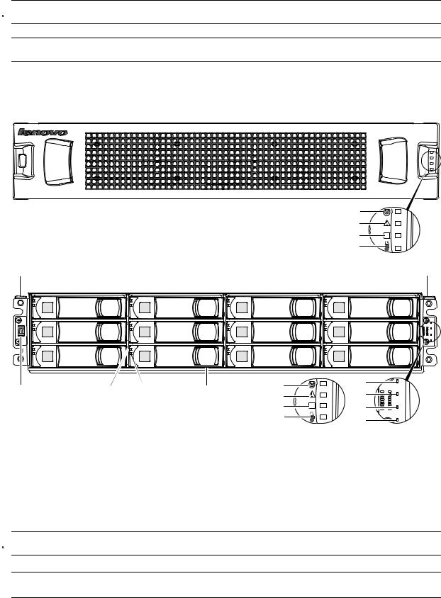


 TIP: See Enclosure bezel attachment and removal on page 56 and Figure 33 on page 57 (2U24).
NOTE: Front and rear panel LEDs for controller enclosures are described in LED descriptions.
12-drive enclosure front panel components
The geometric representation of 2U12 front panel components is identical for S2200 and S3200.
5
6
7
8
Note: Remove this enclosure bezel to access the front panel components shown below.
OK
Left ear |
|
|
|
|
|
Right ear |
|
0 |
1 |
|
2 |
|
3 |
|
4 |
5 |
|
6 |
|
7 |
|
8 |
9 |
|
10 |
|
11 |
1 |
2 |
3 |
4 |
5 |
|
5 |
6 |
|
6 |
||||
|
|
|
|
|
||
|
|
|
|
7 |
OK |
7 |
|
|
|
|
|
||
|
|
|
|
8 |
|
8 |
|
|
|
|
|
|
Note: Integers on disks indicate drive slot numbering sequence. |
(Silk screens on bezel) |
|||
1 |
Enclosure ID LED |
5 |
Enclosure status LED: Unit Locator |
|
2 |
Disk drive status LED: Fault |
6 |
Enclosure status LED: Fault/Service Required |
|
3 |
Disk drive status LED: Power/Activity |
7 |
Enclosure status LED: CRU OK |
|
4 |
3.5" disk or drive blank (typical 12 slots) |
8 |
Enclosure status LED: Temperature Fault |
|
Figure 2 2U12 enclosure: front panel


 TIP: See Enclosure bezel attachment and removal on page 56 and Figure 34 on page 57 (2U12).
NOTE: Front and rear panel LEDs for controller enclosures are described in LED descriptions.
14 Components
Disk drives used in S3200/S2200 enclosures
S3200/S2200 enclosures support LFF/SFF Midline SAS, LFF/SFF Enterprise SAS, and SFF SSD disks. They also support LFF/SFF Midline SAS and LFF/SFF Enterprise self-encrypting disks that work with the Full Disk Encryption (FDE) feature. For information about creating disk groups and adding spares using different disk drive types, see the Lenovo Storage Manager Guide or online help. For S3200 enclosures, also see FDE considerations on page 21.
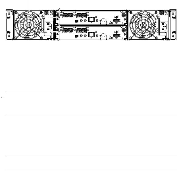
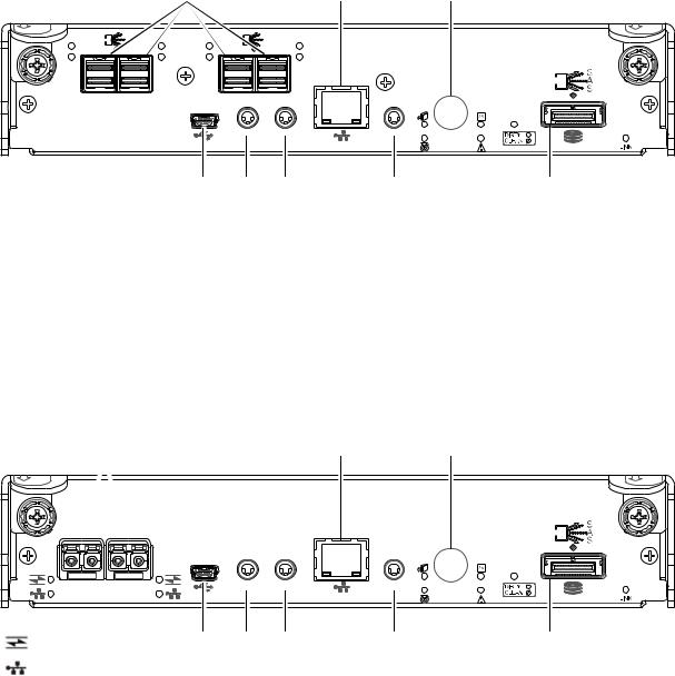
Controller enclosure — rear panel layout
The diagram and table below display and identify important component items that comprise the rear panel layout of a Lenovo Storage S3200/S2200 controller enclosure. Dual 4-port CNC controllers are shown in this representative example of controller enclosure models included in the product series. The rear panel layout applies to the 2U24 and 2U12 form factors.
1 |
1 |
2 |
|
|
|
|
|
|
|
6Gb/s |
PORT 0 |
PORT 1 |
PORT 2 |
PORT 3 |
|
|
|
||
|
|
|
|
|
|
|
|
CACHE |
|
|
|
SERVICE−2 |
CLI |
ACT |
LINK |
SERVICE−1 |
|
|
|
|
CLI |
|
|
|
|
|
3 |
|
|
|
|
|
|
|
6Gb/s |
PORT 0 |
PORT 1 |
PORT 2 |
PORT 3 |
|
|
|
||
|
|
|
|
|||||
|
|
|
|
|
|
|
|
CACHE |
|
|
|
SERVICE−2 |
CLI |
ACT |
LINK |
SERVICE−1 |
|
|
|
|
CLI |
|
|
|
|
|
1AC power supplies
2Controller module A (see face plate detail figures)
CNC controllers are shown in the locator example
3 Controller module B (see face plate detail figures)
Figure 3 S3200/S2200 controller enclosure: rear panel
A controller enclosure accommodates two redundant AC power supply CRUs (see two instances of callout No.1 above). The controller enclosure accommodates up to two controller module CRUs of the same type within the IOM slots (see callouts No.2 and No.3 above).
 IMPORTANT: If the S3200/S2200 controller enclosure is configured with a single controller module, the controller module must be installed in the upper slot (see callout No.2 above), and an I/O module blank must be installed in the lower slot (see callout No.3 above). This configuration is required to allow sufficient air flow through the enclosure during operation.
The diagrams with tables that immediately follow provide descriptions for the different controller modules and power supply modules that can be installed into the rear panel of an S3200/S2200 controller enclosure. Showing controller modules and power supply modules separately from the enclosure enables improved clarity in identifying the component items called out in the diagrams and described in the tables.
Descriptions are also provided for optional drive enclosures supported by S3200/S2200 controller enclosures for expanding storage capacity.
NOTE: S3200/S2200 enclosures support hot-plug replacement of redundant controller modules, fans, power supplies, and expansion modules. Hot-add replacement of drive enclosures is also supported.
Lenovo Storage S3200/S2200 Setup Guide 15
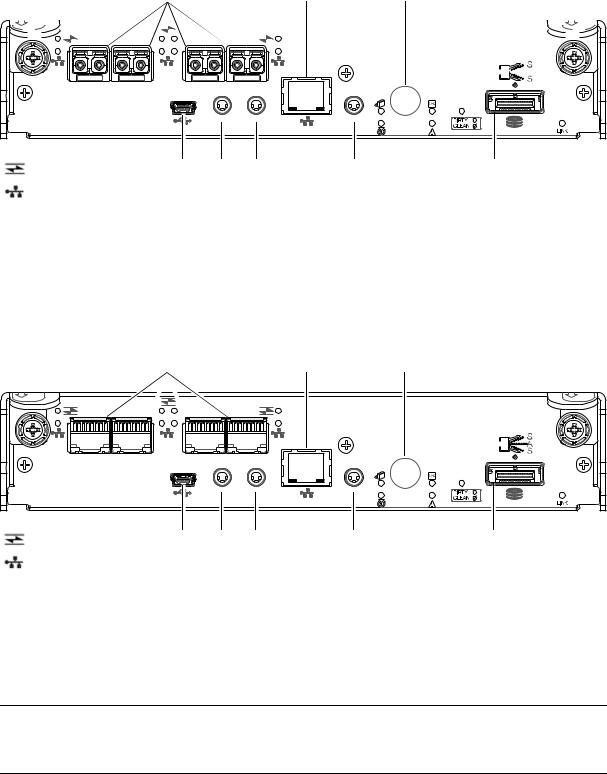
S3200 CNC controller module — rear panel components
Figure 4 shows CNC ports configured with SFPs supporting either 4/8/16 Gb FC or 10GbE iSCSI. The SFPs look identical. Refer to the CNC LEDs that apply to the specific configuration of your CNC ports.
1 |
|
|
|
|
|
|
|
|
|
|
|
|
|
|
|
|
|
5 |
7 |
|
|
|
|
|
|
|
|
||||||||||||||||||||||||||
|
|
|
|
|
|
|
|
|
|
|
|
|
|
|
|
|
|
|
|
|
|
|
|
|
|
|
|
|
|
|
|
|
|
|
|
|
|
|
|
|
|
|
|
|
|
|
|
|
|
|
|
|
|
|
|
|
|
|
|
|
|
|
|
|
|
|
|
|
|
|
|
|
|
|
|
|
|
|
|
|
|
|
|
|
|
|
|
|
|
|
|
|
|
|
|
|
|
|
|
|
|
|
|
|
|
|
|
|
|
|
|
|
|
|
|
|
|
|
|
|
|
|
|
|
|
|
|
|
|
|
|
|
|
|
|
|
|
|
|
|
|
|
|
|
|
|
|
|
|
|
|
|
|
|
|
|
|
|
|
|
|
|
|
|
|
|
|
|
|
|
|
|
|
|
|
|
|
|
|
|
|
|
|
|
|
|
|
|
|
|
|
|
|
|
|
|
|
|
|
|
|
|
|
|
|
|
|
|
|
|
|
|
|
|
|
|
|
|
|
|
|
|
|
|
|
|
|
|
|
|
|
|
|
|
|
|
|
|
|
|
|
|
|
|
|
|
|
|
|
|
|
|
|
|
|
|
|
|
|
|
|
|
|
|
|
|
|
|
|
|
|
|
|
|
|
|
|
|
|
|
|
|
|
|
|
|
|
|
|
|
|
|
|
|
|
|
|
|
|
|
|
|
|
|
|
|
|
|
|
|
|
|
|
|
|
|
|
|
|
|
|
|
|
|
|
|
|
|
|
|
|
|
|
|
|
|
|
|
|
|
|
|
|
|
|
|
|
|
|
|
|
|
|
|
|
|
|
|
|
|
|
|
|
|
|
|
|
|
|
|
|
|
|
|
|
|
|
|
|
|
|
|
|
|
|
|
|
|
|
|
|
|
|
|
|
|
|
|
|
|
|
|
|
|
|
|
|
|
|
|
|
|
|
|
|
|
|
|
|
|
|
|
|
|
|
|
|
|
|
|
|
|
|
|
|
|
|
|
|
|
|
|
|
|
|
|
|
|
|
|
|
|
|
|
|
|
|
|
|
|
|
|
|
|
|
|
|
|
|
|
|
|
|
|
|
|
|
|
|
|
|
|
|
|
|
6Gb/s 


PORT 0 PORT 1 |
PORT 2 PORT 3 |
|
|
|
|
|
|
|
CACHE |
|
|
SERVICE−2 |
CLI |
ACT |
LINK |
SERVICE−1 |
|
|
CLI |
|
|
|
|
|
|
= FC LEDs |
2 |
3 |
4 |
|
|
6 |
8 |
|
= 10GbE iSCSI LEDs |
|
|
|
1 |
CNC ports used for host connection |
5 |
Network port |
|
|
(see Install an SFP transceiver on page 80) |
6 |
Service port 1 (used by service personnel only) |
|
2 |
CLI port (USB - Type B) [see Appendix D] |
|||
7 |
Disabled button (used by engineering only) |
|||
3 |
Service port 2 (used by service personnel only) |
|
(Sticker shown covering the opening) |
|
4 |
Reserved for future use |
8 |
mini-SAS expansion port |
Figure 4 S3200 CNC controller module face plate (FC or 10GbE iSCSI) Figure 5 shows CNC ports configured with 1 Gb RJ-45 SFPs.
|
|
1 |
|
|
|
|
5 |
|
7 |
|
|
|
|
|
|
|
|
|
6Gb/s |
PORT 0 |
PORT 1 |
|
PORT 2 |
PORT 3 |
|
|
|
|
|
|
|
|
|
|
|
|
|
|
CACHE |
|
|
|
SERVICE−2 |
CLI |
ACT |
LINK |
SERVICE−1 |
|
|
|
|
CLI |
|
|
|
|
|
|
|
= FC LEDs |
|
2 |
3 |
|
4 |
|
|
6 |
8 |
= 1Gb iSCSI LEDs (all CNC ports use 1 Gb RJ-45 SFPs in this figure)
1 |
CNC ports used for host connection |
5 |
Network port |
|
|
(see Install an SFP transceiver on page 80) |
6 |
Service port 1 (used by service personnel only) |
|
2 |
CLI port (USB - Type B) [see Appendix D] |
|||
7 |
Disabled button (used by engineering only) |
|||
3 |
Service port 2 (used by service personnel only) |
|
(Sticker shown covering the opening) |
|
4 |
Reserved for future use |
8 |
mini-SAS expansion port |
Figure 5 S3200 CNC controller module face plate (1 Gb RJ-45)
NOTE: See CNC ports used for host connection on page 10 for more information about CNC technology. For CNC port configuration, see the “Configuring host ports” topic within the Storage Manager Guide or online help.
16 Components
S3200 SAS controller module — rear panel components
Figure 6 shows host interface ports configured with 12 Gbit/s HD mini-SAS (SFF-8644) connectors.
|
|
|
1 |
|
|
|
|
5 |
|
7 |
LINK |
12Gb/s |
|
|
|
|
|
LINK |
|
|
|
ACT |
|
ACT |
ACT |
|
|
|
ACT |
|
|
|
|
|
|
|
|
|
|
|
|
|
6Gb/s |
|
SAS 0 |
SAS 1 |
|
SAS 2 |
SAS 3 |
|
|
|
|
|
|
|
|
|
|
|
|
|
|
|
CACHE |
|
|
|
|
SERVICE−2 |
CLI |
ACT |
LINK |
SERVICE−1 |
|
|
|
|
|
CLI |
|
|
|
|
|
|
|
|
|
|
2 |
3 |
|
4 |
|
|
6 |
8 |
1 |
HD mini-SAS ports used for host connection |
6 |
Service port 1 (used by service personnel only) |
|
2 |
CLI port (USB - Type B) [see Appendix D] |
7 |
Disabled button (used by engineering only) |
|
3 |
Service port 2 (used by service personnel only) |
|
(Sticker shown covering the opening) |
|
8 |
mini-SAS expansion port |
|||
4 |
Reserved for future use |
|||
|
|
|||
5 |
Network port |
|
|
Figure 6 S3200 SAS controller module face plate (HD mini-SAS)
S2200 CNC controller module — rear panel components
Figure 7 shows CNC ports configured with SFPs supporting either 4/8/16 Gb FC or 10GbE iSCSI. The SFPs look identical. Refer to the CNC LEDs that apply to the specific configuration of your CNC ports.
1 |
5 |
7 |
|
|
6Gb/s |
|
|
CACHE |
PORT 0 |
PORT 1 |
|
SERVICE−2 |
CLI |
ACT |
LINK |
SERVICE−1 |
|
|
|
CLI |
|
|
|
|
|
|
= FC LEDs |
|
2 |
3 |
4 |
|
|
6 |
8 |
|
= 10GbE iSCSI LEDs |
|
|
|
1 |
CNC ports used for host connection |
5 |
Network port |
|
|
(see Install an SFP transceiver on page 80) |
6 |
Service port 1 (used by service personnel only) |
|
2 |
CLI port (USB - Type B) [see Appendix D] |
|||
7 |
Disabled button (used by engineering only) |
|||
3 |
Service port 2 (used by service personnel only) |
|
(Sticker shown covering the opening) |
|
4 |
Reserved for future use |
8 |
mini-SAS expansion port |
Figure 7 S2200 CNC controller module face plate (FC or 10GbE iSCSI)
Lenovo Storage S3200/S2200 Setup Guide 17
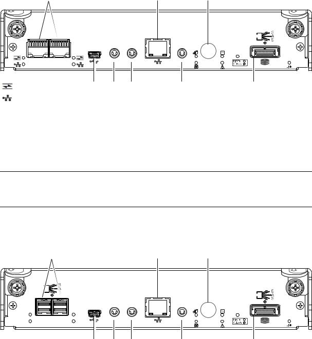
Figure 8 shows CNC ports configured with 1 Gb RJ-45 SFPs.
1 |
5 |
7 |
|
|
6Gb/s |
|
|
|
|
|
|
|
|
CACHE |
PORT 0 |
PORT 1 |
|
SERVICE−2 |
CLI |
ACT |
LINK |
SERVICE−1 |
|
|
|
CLI |
|
|
|
|
|
|
= FC LEDs |
|
2 |
3 |
4 |
|
|
6 |
8 |
= 1Gb iSCSI LEDs (both CNC ports use 1 Gb RJ-45 SFPs in this figure)
1 |
CNC ports used for host connection |
5 |
Network port |
|
|
(see Install an SFP transceiver on page 80) |
6 |
Service port 1 (used by service personnel only) |
|
2 |
CLI port (USB - Type B) [see Appendix D] |
|||
7 |
Disabled button (used by engineering only) |
|||
3 |
Service port 2 (used by service personnel only) |
|
(Sticker shown covering the opening) |
|
4 |
Reserved for future use |
8 |
mini-SAS expansion port |
Figure 8 S2200 CNC controller module face plate (1 Gb RJ-45)
NOTE: See CNC ports used for host connection on page 10 for more information about CNC technology. For CNC port configuration, see the “Configuring host ports” topic within the Storage Manager Guide or online help.
S2200 SAS controller module — rear panel components
Figure 9 shows host interface ports configured with 12 Gbit/s HD mini-SAS (SFF-8644) connectors.
1 |
5 |
7 |
|
|
6Gb/s |
LINK |
|
LINK |
|
|
|
|
|
|
CACHE |
SAS 0 |
SAS 1 |
|
|
SERVICE−2 |
CLI |
ACT |
LINK |
SERVICE−1 |
|
ACT |
|
ACT |
CLI |
|
|
|
|
|
|
|
|
|
2 |
3 |
4 |
|
|
6 |
8 |
1HD mini-SAS ports used for host connection
2CLI port (USB - Type B) [see Appendix D]
3Service port 2 (used by service personnel only)
4Reserved for future use
5Network port
6Service port 1 (used by service personnel only)
7Disabled button (used by engineering only) (Sticker shown covering the opening)
8mini-SAS expansion port
Figure 9 S2200 SAS controller module face plate (HD mini-SAS)
18 Components
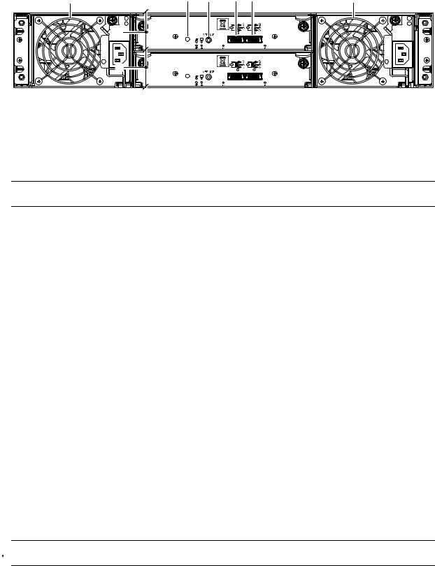
E1024/E1012 drive enclosure rear panel components
S3200/S2200 controller enclosures support SFF E1024 24-disk and LFF E1012 12-disk drive enclosures in the 2U form factor for expansion of storage capacity. These drive enclosures use mini-SAS (SFF-8088) connectors to facilitate backend SAS expansion. The rear panel view is common to both drive enclosures. See Cable requirements for storage enclosures on page 23 for cabling information.
1 |
4 |
5 |
6 |
7 |
1 |
|
|
|
0 |
0 |
|
|
2 |
|
|
|
|
|
|
|
IN |
OUT |
|
|
|
|
0 |
0 |
|
|
3 |
|
|
|
|
IN OUT
1 |
Power supplies (AC shown) |
5 |
Service port (used by service personnel only) |
2 |
Expansion module A |
6 |
SAS In port |
3 |
Expansion module B |
7 |
SAS Out port |
4 |
Disabled button (used by engineering/test only) |
|
|
Figure 10 Drive enclosure rear panel view (2U form factor)
NOTE: See Connecting the controller enclosure and drive enclosures on page 22 for more information.
Component installation and replacement
Installation and replacement of S3200/S2200 CRUs (customer-replaceable units) is addressed in the
Lenovo Storage CRU Installation and Replacement Guide within the “Procedures” chapter. CRU procedures facilitate replacement of a damaged chassis or chassis component:
•Replacing a controller or expansion module
•Replacing a disk drive module
•Replacing a Fibre Channel transceiver
•Replacing a 10GbE SFP+ transceiver
•Replacing a 1 Gb SFP transceiver
•Replacing a controller enclosure chassis
For additional information, contact support.lenovo.com, select Product Support, and navigate to Storage Products.
Cache
To enable faster data access from disk storage, the following types of caching are performed:
•Write-back or write-through caching. The controller writes user data into the cache memory in the controller module rather than directly to the disks. Later, when the storage system is either idle or aging —and continuing to receive new I/O data—the controller writes the data to the disks.
•Read-ahead caching. The controller detects sequential data access, reads ahead into the next sequence of data—based upon settings—and stores the data in the read-ahead cache. Then, if the next read access is for cached data, the controller immediately loads the data into the system memory, avoiding the latency of a disk access.


 TIP: See the Storage Management Guide for more information about cache options and settings.
Lenovo Storage S3200/S2200 Setup Guide 19
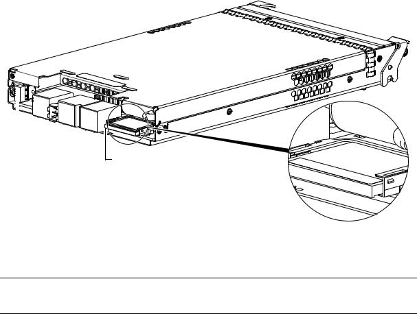
CompactFlash
During a power loss or controller failure, data stored in cache is saved off to non-volatile memory (CompactFlash). The data is restored to cache, and then written to disk after the issue is corrected. To protect against writing incomplete data to disk, the image stored on the CompactFlash is verified before committing to disk.
The CompactFlash memory card is located at the midplane-facing end of the controller module as shown below. Do not remove the card; it is used for cache recovery only.
Controller module pictorial (Midplane-facing rear view)
CompactFlash memory card
Used |
for Do not |
|
|
|
|
|
|
||
|
cache |
|
remove |
|
|
|
recovery |
only |
|
|
|
|
|
|
Figure 11 CompactFlash memory card
For additional information, contact support.lenovo.com, select Product Support, and navigate to Storage Products.
NOTE: In dual-controller configurations featuring one healthy partner controller, cache is duplicated between the controllers (subject to volume write optimization setting).
Supercapacitor pack
To protect controller module cache in case of power failure, each controller enclosure model is equipped with supercapacitor technology, in conjunction with CompactFlash memory, built into each controller module to provide extended cache memory backup time. The supercapacitor pack provides energy for backing up unwritten data in the write cache to the CompactFlash, in the event of a power failure. Unwritten data in CompactFlash memory is automatically committed to disk media when power is restored. In the event of power failure, while cache is maintained by the supercapacitor pack, the Cache Status LED flashes at a rate of 1/10 second on and 9/10 second off.
20 Components
2 Installing the enclosures
Installation checklist
The following table outlines the steps required to install the enclosures, and initially configure and provision the storage system. To ensure successful installation, perform the tasks in the order presented.
Table 3 Installation checklist
Step |
Task |
Where to find procedure |
|
|
|
1. |
Install the controller enclosure and optional |
See the rack-mount bracket kit installation instructions |
|
drive enclosures in the rack, and attach the |
pertaining to your enclosure. Also refer to the bezel |
|
enclosure bezel.1 |
attachment instructions for your enclosure |
2. |
Connect controller enclosure and optional |
See Connecting the controller enclosure and drive enclosures |
|
drive enclosures. |
on page 22. |
|
|
|
3. |
Connect power cords. |
See Powering on/powering off on page 28. |
|
|
|
4. |
Test enclosure connectivity. |
See Testing enclosure connections on page 28. |
|
|
|
5. |
Install required host software. |
See Host system requirements on page 30. |
|
|
|
6. |
Connect hosts.2 |
See Connecting the enclosure to hosts on page 30. |
7. |
Connect remote management hosts.2 |
See Connecting a management host on the network, |
|
|
page 40. |
|
|
|
8. |
Obtain IP values and set network port IP |
See Obtaining IP values on page 41. |
|
properties on the controller enclosure. |
For USB CLI port and cable use, see Appendix D. |
|
|
|
9. |
Use the CLI to set the host interface protocol. |
See CNC technology on page 30. The CNC models allow |
|
|
you to set the host interface protocol for your qualified SFP |
|
|
option. Use the set host-port-mode command as |
|
|
described in the CLI Reference Guide or online help. |
|
|
|
10. |
Perform initial configuration tasks3: |
Topics below correspond to bullets at left: |
|
• Sign-in to the web-browser interface to |
See “Getting Started” in the web-posted Lenovo Storage |
|
access the application GUI. |
Manager Guide. |
|
• Verify firmware revisions and update if |
See Updating firmware. Also see the same topic in the |
|
necessary. |
Storage Manager Guide. |
|
• Initially configure and provision the system |
See “Configuring the System” and “Provisioning the System” |
|
using the Storage Management Console. |
topics in the Storage Manager Guide or online help. |
|
|
|
1See the Lenovo Storage CRU Installation and Replacement Guide for illustrations and narrative describing attachment of enclosure bezels to 2U24 and 2U12 chassis. See also Enclosure bezel attachment and removal on page 56.
2For more about hosts, see the “About hosts” topic in the Storage Manager Guide.
3The Storage Management Console is introduced in Accessing the SMC on page 45. See the Storage Manager Guide or online help for additional information.
NOTE: Additional installation notes:
•Controller modules within the same enclosure must be of the same type.
•For optimal performance, do not mix 6 Gb and 3 Gb disk drives within the same enclosure.
FDE considerations
The Full Disk Encryption feature available via the management interfaces requires use of self-encrypting drives (SED) which are also referred to as FDE-capable disk drive modules. When installing FDE-capable disk drive modules, follow the same procedures for installing disks that do not support FDE. The exception occurs when you move FDE-capable disk drive modules for one or more disk groups to a different system, which requires additional steps.
Lenovo Storage S3200/S2200 Setup Guide 21
The procedures for using the FDE feature, such as securing the system, viewing disk FDE status, and clearing and importing keys are performed using the web-based SMC application or CLI commands (see the Storage Manager Guide or the CLI Reference Guide for more information).
NOTE: When moving FDE-capable disk drive modules for a disk group, stop I/O to any disk groups before removing the disk drive modules. Follow the “Removing a disk drive module” and “Installing a disk drive module” procedures within the CRU Installation and Replacement Guide. Import the keys for the disks so that the disk content becomes available.
While replacing or installing FDE-capable disk drive modules, consider the following:
•If you are installing FDE-capable disk drive modules that do not have keys into a secure system, the system will automatically secure the disks after installation. Your system will associate its existing key with the disks, and you can transparently use the newly-secured disks.
•If the FDE-capable disk drive modules originate from another secure system, and contain that system’s key, the new disks will have the Secure, Locked status. The data will be unavailable until you enter the passphrase for the other system to import its key. Your system will then recognize the metadata of the disk groups and incorporate it. The disks will have the status of Secure, Unlocked and their contents will be available:
•To view the FDE status of disks, use the SMC or the show fde-state CLI command.
•To import a key and incorporate the foreign disks, use the SMC or the set fde-import-key CLI command.
NOTE: If the FDE-capable disks contain multiple keys, you will need to perform the key importing process for each key to make the content associated with each key become available.
•If you do not want to retain the disks’ data, you can repurpose the disks. Repurposing disks deletes all disk data, including lock keys, and associates the current system’s lock key with the disks.
To repurpose disks, use the SMC or the set disk CLI command.
•You need not secure your system to use FDE-capable disks. If you install all FDE-capable disks into a system that is not secure, they will function exactly like disks that do not support FDE. As such, the data they contain will not be encrypted. If you decide later that you want to secure the system, all of the disks must be FDE-capable.
•If you install a disk module that does not support FDE into a secure system, the disk will have the Unusable status and will be unavailable for use.
•If you are re-installing your FDE-capable disk drive modules as part of the process to replace the chassis-and-midplane CRU, you must insert the original disks and re-enter their FDE passprhase (see the
CRU Installation and Replacement Guide for more information).
Connecting the controller enclosure and drive enclosures
Lenovo Storage S3200/S2200 controller enclosures support these maximum configurations:
•S3200 enclosures—available in 24-drive (2.5") or 12-drive (3.5") chassis—support up to eight enclosures (including the controller enclosure), or a maximum of 192 disk drives.
•S2200 enclosures—available in 24-drive (2.5") or 12-drive (3.5") chassis—support up to four enclosures (including the controller enclosure), or a maximum of 96 disk drives.
The S3200/S2200 enclosures support both straight-through and reverse SAS cabling. Reverse cabling allows any drive enclosure to fail—or be removed—while maintaining access to other enclosures. Fault tolerance and performance requirements determine whether to optimize the configuration for high availability or high performance when cabling. The S3200/S2200 controller modules support both 3-Gbps and 6-Gbps internal disk drive speeds together with 3-Gbps and 6-Gbps expander link speeds.
22 Installing the enclosures

 CAUTION: Some 6-Gbps disks might not consistently support a 6-Gbps transfer rate. If this happens, the system automatically adjusts transfers to those disks to 3 Gbps, increasing reliability and reducing error messages with little impact on system performance. This rate adjustment persists until the controller is restarted or power-cycled.
The S3200/S2200 controller enclosures support compatible Lenovo drive enclosures for adding storage. Supported enclosure form factors include traditional 2U models (2U12 and 2U24). A summary overview of drive enclosures supported by controller enclosures is provided herein.
Cabling diagrams in this section show fault-tolerant cabling patterns. Controller and expansion modules are identified by <enclosure-ID><controller-ID>. When connecting multiple drive enclosures, use reverse cabling to ensure the highest level of fault tolerance, enabling controllers to access remaining drive enclosures if a drive enclosure fails.
For example, the illustration on the left in Figure 13 on page 26 shows reverse cabling, wherein controller 0A (i.e., enclosure-ID = 0; controller-ID = Able) is connected to expansion module 1A, with a chain of connections cascading down (blue). Controller 0B is connected to the lower expansion module (B) of the last drive enclosure in the chain, with connections moving in the opposite direction (green). Cabling examples are provided on the following pages.
Connecting the S3200/S2200 controller to the 2U12 drive enclosure
The LFF E1012 12-drive enclosure, supporting 6 Gb internal disk drive and expander link speeds, can be attached to a S3200/S2200 controller enclosure using supported mini-SAS to mini-SAS cables of 0.5 m (1.64') to 2 m (6.56') length (see Figure 12 on page 25).
Connecting the S3200/S2200 controller to the 2U24 drive enclosure
The SFF E1024 24-drive enclosure, supporting 6 Gb internal disk drive and expander link speeds, can be attached to a S3200/S2200 controller enclosure using supported mini-SAS to mini-SAS cables of 0.5 m (1.64') to 2 m (6.56') length (see Figure 12 on page 25).
Connecting the S3200/S2200 controller to mixed model drive enclosures
The S3200/S2200 controllers support cabling of 6 Gb SAS link-rate SFF and LFF expansion modules—in mixed model fashion—as shown in Figure 13 on page 26. The simplified rear-panel views of the E1024 and E1012 are identical.
Cable requirements for storage enclosures
The S3200/S2200 enclosures support 6-Gbps or 3-Gbps expansion port data rates. Use only Lenovo Storage or OEM-qualified cables, and observe the following guidelines (see Table 4 on page 24):
•When installing SAS cables to expansion modules, use only supported mini-SAS x4 cables with SFF-8088 connectors supporting your 6 Gb application.
•Qualified mini-SAS to mini-SAS 0.5 m (1.64') cables are used to connect cascaded enclosures in the rack. The “mini-SAS to mini-SAS” cable designator connotes SFF-8088 to SFF-8088 connectors.
•The maximum expansion cable length allowed in any configuration is 2 m (6.56').
•Cables required, if not included, must be separately purchased.
•When adding more than two drive enclosures, you may need to purchase additional cables, depending upon number of enclosures and cabling method used.
•You may need to order additional or longer cables when reverse-cabling a fault-tolerant configuration (see Figure 14 on page 27).
•Use only Lenovo Storage or OEM-qualified cables for host connection:
•Qualified Fibre Channel SFP and cable options
•Qualified 10GbE iSCSI SFP and cable options
•Qualified 1 Gb RJ-45 SFP and cable options
Lenovo Storage S3200/S2200 Setup Guide 23
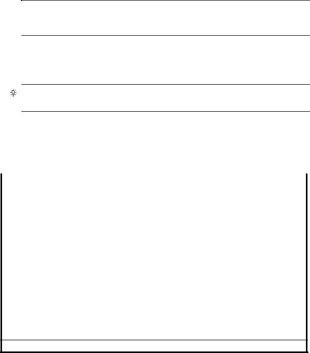
•Qualified HD mini-SAS cable and fan-out cable options supporting SFF-8644 and SFF-8088 host connection (also see HD mini-SAS host connection on page 33):
•A qualified SFF-8466 to SFF-8466 cable option is used for connecting to a 12 Gbit/s enabled host.
•A qualified SFF-8644 to SFF-8088 cable option is used for connecting to a 6 Gbit/s enabled host.
•A qualified bifurcated SFF-8644 to SFF-8644 fan-out cable option is used for connecting to a 12 Gbit/s enabled host.
NOTE: Using fan-out cables instead of standard cables will double the number of hosts that can be attached to a single system. Use of fan-out cables will halve the maximum bandwidth available to each host, but overall bandwidth available to all hosts is unchanged.
•A qualified bifurcated SFF-8644 to SFF-8088 fan-out cable option is used for connecting to a 6 Gbit/s enabled host (see Note above).
See HD mini-SAS host connection on page 33 and SAS fan-out cable option for more information about bifurcated SAS cables.
TIP: Requirements for cabling S3200/S2200 controller enclosures and supported drive enclosures are summarized in Table 4 on page 24.
Table 4 on page 24 summarizes key characteristics of controller enclosures and compatible drive (expansion) enclosures relative to cabling, including: the cable type needed for attaching one specific enclosure model to another specific enclosure model; internal disk drive speeds; number of disks of given size (SFF or LFF) supported per enclosure model; and SAS expander data rates. Enclosure form factor and NEBS compliance information are also provided.
Table 4 Summary of cabling connections for S3200/S2200 enclosures
Model |
Form |
Host connect |
NEBS |
SFF 24-disk chassis |
LFF 12-disk chassis |
|
|
|
|
|
|
S3200/S22001,2 |
2U24 |
FC (8/16 Gb) SFP option |
Note 4 |
mini-SAS to mini-SAS |
mini-SAS to mini-SAS |
|
2U12 |
FC (8/16 Gb) SFP option |
Note 4 |
mini-SAS to mini-SAS |
mini-SAS to mini-SAS |
|
|
|
|
|
|
S3200/S22001,2 |
2U24 |
10GbE iSCSI SFP option |
Note 4 |
mini-SAS to mini-SAS |
mini-SAS to mini-SAS |
|
2U12 |
10GbE iSCSI SFP option |
Note 4 |
mini-SAS to mini-SAS |
mini-SAS to mini-SAS |
|
|
|
|
|
|
S3200/S22001,2 |
2U24 |
1 Gb iSCSI SFP option |
Note 4 |
mini-SAS to mini-SAS |
mini-SAS to mini-SAS |
|
2U12 |
1 Gb iSCSI SFP option |
Note 4 |
mini-SAS to mini-SAS |
mini-SAS to mini-SAS |
|
|
|
|
|
|
S3200/S22001,3 |
2U24 |
HD mini-SAS connector |
Note 4 |
mini-SAS to mini-SAS |
mini-SAS to mini-SAS |
|
2U12 |
HD mini-SAS connector |
Note 4 |
mini-SAS to mini-SAS |
mini-SAS to mini-SAS |
|
|
|
|
|
|
E1024 |
2U24 |
|
Note 4 |
mini-SAS to mini-SAS |
mini-SAS to mini-SAS |
|
|
|
|
|
|
E1012 |
2U12 |
|
Note 4 |
mini-SAS to mini-SAS |
mini-SAS to mini-SAS |
|
|
|
|
|
|
Enclosure chassis designators:
2U24: Enclosure measuring two rack units high, providing 24 SFF (2.5") sledded disk drive modules. 2U12: Enclosure measuring two rack units high, providing 12 LFF (3.5") sledded disk drive modules.
See Physical requirements on page 73 for more information about 2U24 and 2U12 enclosures.
1These compatible product models feature 6 Gbit/s internal disk and SAS expander link speeds.
2See CNC technology on page 30 for information about locating and installing qualified SFP options into CNC ports.
3See 12 Gb mini-SAS ports on page 32 for information about host connection using SFF-8644 high-density mini-SAS connectors. 4NEBS compliance is a future consideration for S3200/S2200 enclosures.
5The S3200 and S2200 enclosures support single or dual-IOMs.
24 Installing the enclosures
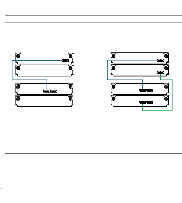
Summary of drive enclosure cabling illustrations
The following illustrations show both reverse and straight-through cabling examples featuring S3200/S2200 controller enclosures and compatible E1024 (2U24), and E1012 (2U12) drive enclosures. The rear-panel views of the E1024 and E1012 are identical. All storage enclosures use mini-SAS connectors for expansion.
NOTE: The S3200/S2200 controller enclosures and compatible drive enclosures support 6 Gb SFF-8088 mini-SAS connectors for adding storage. See Table 4 for SAS cable requirements.
NOTE: For clarity, the schematic diagrams show only relevant details such as face plate outlines and expansion ports. For detailed illustrations, see Controller enclosure — rear panel layout on page 15. Also see the controller module face plate illustrations that follow the rear panel layout.
0A |
Controller A |
|
|
|
|
0B |
IOM blank |
|
1A |
In |
Out |
|
||
1B |
IOM blank |
|
|
Controller A |
0A |
|
|
|
Controller |
|
|
enclosure |
Controller B |
0B |
0 |
||
|
In |
1A |
Drive |
Out |
|
|
|
|
enclosure |
|
1B |
1 |
In |
|
|
Out |
Enclosures equipped with single IOM |
Enclosures equipped with dual IOMs |
Figure 12 Cabling connections between a controller enclosure and one 2U drive enclosure
The figures above show examples of an S3200 or S2200 controller enclosure cabled to a single drive enclosure. Supported drive enclosures are ordered separately.
NOTE: The E1024 and E1012 drive enclosures can be configured with single or dual expansion canisters.
Within Figure 12, the illustration on the left shows cabling of enclosures equipped with a single IOM. The empty IOM slot in each of the enclosures is covered with an IOM blank to ensure sufficient air flow during enclosure operation. The illustration on the right shows cabling of enclosures equipped with dual IOMs.
The remaining illustrations in the section feature enclosures equipped with dual IOMs.
 IMPORTANT: If the S3200/S2200 controller enclosure is configured with a single controller module, it must be installed in the upper slot, and an I/O module blank must be installed in the lower slot (shown above). This configuration is required to allow sufficient air flow through the enclosure during operation.
See the “Replacing a controller or expansion module” topic within the Lenovo CRU Installation and Replacement Guide for additional information.
Lenovo Storage S3200/S2200 Setup Guide 25
NOTE: Controller enclosures and optional/cascaded drive enclosures
•Figure 13 on page 26 shows maximum supported enclosures for an S2200 array.
•Figure 14 on page 27 shows maximum supported enclosures for an S3200 array.
0A |
Controller A |
Controller |
|
|
|
|
|
0B |
Controller B |
enclosure |
|
0 |
|||
1A |
In |
Out |
|
|
Drive |
||
|
|
||
|
|
|
|
1B |
In |
Out |
enclosure |
1 |
|||
2A |
In |
Out |
|
|
|
|
|
|
|
|
Drive |
2B |
In |
Out |
enclosure |
|
|
2 |
|
|
In |
Out |
|
3A |
|
|
Drive |
|
|
|
|
3B |
In |
Out |
enclosure |
|
|
3 |
|
Reverse cabling
Controller A |
0A |
|
|
|
|
Controller B |
0B |
|
In |
Out |
1A |
|
||
|
|
|
In |
Out |
1B |
In |
Out |
2A |
In |
Out |
2B |
|
|
|
In |
Out |
3A |
|
|
|
In |
Out |
3B |
|
|
|
Straight-through cabling
Figure 13 Fault-tolerant cabling between a dual-controller enclosure and three 2U drive enclosures
The diagram at left (above) shows reverse cabling of a S3200/S2200 dual-controller enclosure and 2U drive enclosures configured with dual-expansion modules. Controller module 0A is connected to expansion module 1A, with a chain of connections cascading down (blue). Controller module 0B is connected to the lower expansion module (3B), of the last expansion enclosure, with connections moving in the opposite direction (green). Reverse cabling allows any expansion enclosure to fail—or be removed—while maintaining access to other enclosures.
The diagram at right (above) shows the same storage components connected using straight-through cabling. Using this method, if an expansion enclosure fails, the enclosures that follow the failed enclosure in the chain are no longer accessible until the failed enclosure is repaired or replaced.
The 2U drive enclosures shown in Figure 13 can either be of the same type (all E1024s or all E1012s) or they can be a mixture of these models. Given that supported drive enclosure models use 6 Gb SAS link-rate and SAS2.0 expanders, they can be ordered in desired sequence within the array, following the controller enclosure.
Refer to these diagrams when cabling multiple compatible drive enclosures together with the S3200 or S2200 controller enclosure.
 IMPORTANT: Guidelines for stacking enclosures in the rack are provided in the rackmount bracket kit installation sheet provided with your product.
26 Installing the enclosures
Loading...