


 Loading...
Lenovo 9859, 9952, 9622, 7098, 9785 User Manual
...

ThinkCentre
Hardware Installation and Replacement
Guide

Note
Before using this information and the product it supports, be sure to read and understand the Safety and Warranty Guide for this product and “Notices,” on page 45.
First Edition (February 2008)
© Copyright Lenovo 2005, 2008.
Portions © Copyright International Business Machines Corporation 2005. All rights reserved.
LENOVO products, data, computer software, and services have been developed exclusively at private expense and are sold to governmental entities as commercial items as defined by 48 C.F.R. 2.101 with limited and restricted rights to use, reproduction and disclosure.
LIMITED AND RESTRICTED RIGHTS NOTICE: If products, data, computer software, or services are delivered pursuant a General Services Administration ″GSA″ contract, use, reproduction, or disclosure is subject to restrictions set forth in Contract No. GS-35F-05925.

Contents
Figures . . . . . . . . . . . . . . |
. |
v |
Replacing the heat sink . . . . . . . . . |
. |
25 |
|
|
|
|
Replacing a hard disk drive . . . . . . . . |
. |
27 |
|
Chapter 1. Important safety information |
|
1 |
Replacing an optical drive . . . . . . . . |
. |
29 |
|
|
|
|
Replacing the diskette drive . . . . . . . . |
. |
31 |
|
Chapter 2. Overview . . . . . . . . |
. |
3 |
Installing or replacing a memory module . . . |
. 32 |
||
Replacing a adapter card . . . . . . . . . |
. |
34 |
||||
Additional information resources . . . . . . |
. |
3 |
||||
Replacing the fan assembly . . . . . . . . |
. |
35 |
||||
Handling static-sensitive devices. . . . . . . |
. |
4 |
||||
Replacing the keyboard . . . . . . . . . |
. |
37 |
||||
Locations . . . . . . . . . . . . . . |
. |
5 |
||||
Replacing the mouse . . . . . . . . . . |
. |
37 |
||||
Locating controls and connectors on the front of |
|
|
||||
|
|
|
|
|
||
your computer. . . . . . . . . . . . |
. |
5 |
Chapter 4. Completing the parts |
|
|
|
Locating connectors on the rear of your computer |
6 |
|
|
|||
replacement . . . . . . . . . . . |
. |
39 |
||||
Locating components . . . . . . . . . |
. |
8 |
||||
Updating (flashing) BIOS from a diskette or |
|
|
||||
Identifying parts on the system board . . . . . 9 |
|
|
||||
CD-ROM . . . . . . . . . . . . . . . 41 |
||||||
|
|
|
||||
Chapter 3. Installing options and |
|
|
Recovering from a POST/BIOS update failure . . |
. 41 |
||
|
|
Obtaining device drivers . . . . . . . . . |
. |
42 |
||
replacing hardware . . . . . . . . . |
11 |
|||||
|
|
|
||||
Installing external options . . . . . . . . |
. |
11 |
Chapter 5. Security features . . . . |
. |
43 |
|
Installing internal options . . . . . . . . |
. |
12 |
||||
Integrated cable lock . . . . . . . . . . |
. |
43 |
||||
Opening the cover . . . . . . . . . . |
. |
12 |
||||
Password protection . . . . . . . . . . |
. |
44 |
||||
Accessing system board components and drives |
|
13 |
||||
|
|
|
|
|||
Installing adapter cards . . . . . . . . |
. |
14 |
Appendix. Notices . . . . . . . . . |
. |
45 |
|
Installing internal drives . . . . . . . . |
. |
15 |
||||
Television output notice . . . . . . . . . |
. |
46 |
||||
Erasing a lost or forgotten password (clearing |
|
|
||||
CMOS) . . . . . . . . . . . . . . . |
. |
20 |
Trademarks . . . . . . . . . . . . . |
. |
46 |
|
Replacing the battery . . . . . . . . . . |
. |
22 |
Index . . . . . . . . . . . . . . |
. |
47 |
|
Replacing the power supply assembly . . . . |
. 23 |
|||||
© Lenovo 2005, 2008. Portions © IBM Corp. 2005. |
iii |
iv ThinkCentre Hardware Installation and Replacement Guide

Figures
1. |
Controls and connectors. . . . . . . |
. |
. |
5 |
20. |
Accessing the heat sink . . . . . . . |
. |
25 |
2. |
Connector locations . . . . . . . . |
. |
. |
6 |
21. |
Removing the heat sink . . . . . . . |
. |
26 |
3. |
Component locations. . . . . . . . |
. |
. |
8 |
22. |
Accessing the hard drive . . . . . . . |
. |
27 |
4. |
System board parts locations . . . . . |
. |
. |
9 |
23. |
Removing the hard disk drive . . . . . |
. |
28 |
5. |
Pivoting the cover . . . . . . . . . |
. |
|
12 |
24. |
Removing the hard disk drive and |
|
|
6. |
Pivoting the drive bay . . . . . . . . |
. |
|
13 |
|
disconnecting the cables . . . . . . . |
. |
29 |
7. |
Installing the adapter card . . . . . . |
. |
|
14 |
25. |
Accessing the optical drive . . . . . . |
. |
30 |
8. |
Drive bay locations . . . . . . . . . |
. |
|
16 |
26. |
Removing the optical drive . . . . . . |
. |
30 |
9. |
Pivoting the drive bay . . . . . . . . |
. |
|
17 |
27. |
Accessing the diskette drive . . . . . . |
. |
31 |
10. |
Locking the optical drive . . . . . . . |
. |
|
18 |
28. |
Removing the diskette drive . . . . . . |
. |
32 |
11. Connecting the five-wire power connector to |
|
|
|
29. |
Removing the memory module . . . . . |
. 33 |
||
|
the drive . . . . . . . . . . . . |
. |
|
19 |
30. |
Installing the memory module . . . . . |
. |
34 |
12. |
Removing the front bezel . . . . . . . |
. 19 |
31. |
Opening the adapter card retainer and |
|
|
||
13. |
Installing a new drive . . . . . . . . |
. |
|
20 |
|
removing the adapter card . . . . . . |
. |
35 |
14. |
Battery removal . . . . . . . . . . |
. |
|
22 |
32. |
Accessing the fan assembly . . . . . . |
. |
36 |
15. |
Battery installation . . . . . . . . . |
. |
|
22 |
33. |
Keyboard connectors, standard and USB |
|
37 |
16. |
Power-supply-retaining screws . . . . . |
. |
|
23 |
34. |
Replacing a mouse . . . . . . . . . |
. |
38 |
17. |
Accessing the system board . . . . . . |
. |
|
23 |
35. |
Cable routing . . . . . . . . . . . |
. |
39 |
18. |
System-board connectors . . . . . . . |
. |
|
24 |
36. |
Integrated cable lock . . . . . . . . |
. |
43 |
19. |
Removing the power supply . . . . . . |
. 24 |
|
|
|
|
||
© Lenovo 2005, 2008. Portions © IBM Corp. 2005. |
v |
vi ThinkCentre Hardware Installation and Replacement Guide

Chapter 1. Important safety information
CAUTION:
Before using this manual, it is important that you read and understand all the related safety information for this product. Refer to the Safety and Warranty Guide that you received with this product for the latest safety information. Reading and understanding the safety information reduces the risk of personal injury and damage to your product.
© Lenovo 2005, 2008. Portions © IBM Corp. 2005. |
1 |
2 ThinkCentre Hardware Installation and Replacement Guide
Chapter 2. Overview
This guide provides information about replacing Customer Replaceable Units (CRUs).
This guide does not include procedures for all parts. It is expected that cables, switches, and certain mechanical parts be replaced by trained service personnel without the need for step-by-step procedures.
Note: Use only parts provided by Lenovo®.
This guide contains instructions for installing and or replacing the following parts:
vBattery
vPower supply
vHeat sink
vHard disk drive
vOptical drive
vDiskette drive
vMemory modules
vPCI adapter
vSystem fan assembly
vRear fan assembly
vKeyboard
vMouse
Additional information resources
If you have Internet access, the most up-to-date information for your computer is available from the World Wide Web.
You can find:
vCRU removal and installation information
vCRU removal and installation videos
vPublications
vTroubleshooting information
vParts information
vDownloads and drivers
vLinks to other useful sources of information
vSupport phone list
To access this information, go to:
http://www.lenovo.com/support
© Lenovo 2005, 2008. Portions © IBM Corp. 2005. |
3 |

Handling static-sensitive devices
Do not open the static-protective package containing the new part until the defective part has been removed from the computer and you are ready to install the new part. Static electricity, although harmless to you, can seriously damage computer components and parts.
When you handle parts and other computer components, take these precautions to avoid static-electricity damage:
vLimit your movement. Movement can cause static electricity to build up around you.
vAlways handle parts and other computer components carefully. Handle adapters, memory modules, system boards, and microprocessors by the edges. Never touch any exposed circuitry.
vPrevent others from touching the parts and other computer components.
vBefore you replace a new part, touch the static-protective package containing the part to a metal expansion-slot cover or other unpainted metal surface on the computer for at least two seconds. This reduces static electricity in the package and your body.
vWhen possible, remove the new part from the static-protective packaging, and install it directly in the computer without setting the part down. When this is not possible, place the static-protective package that the part came in on a smooth, level surface and place the part on it.
vDo not place the part on the computer cover or other metal surface.
4 ThinkCentre Hardware Installation and Replacement Guide
Locations
This chapter provides illustrations to help locate the various connectors, controls, and components of the computer.
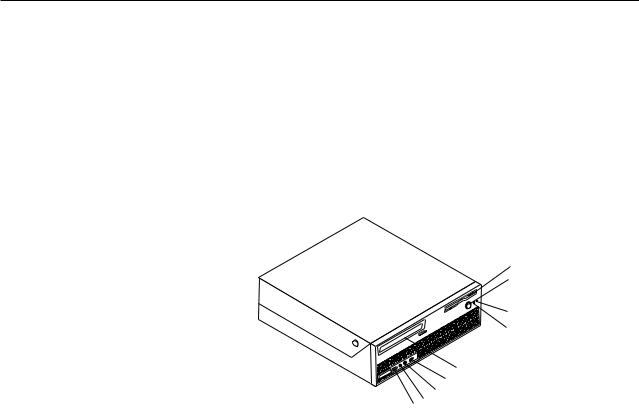
Locating controls and connectors on the front of your computer
Figure 1 shows the location of the controls and connectors on the front of your computer.
Note: Not all computer models will have the following controls and connections.
Figure 1. Controls and connectors |
|
|
|
|
|
|
|
|
|
|
|
|
|
|
|
|
|
|
|
|
|
|
|
|
|
|
|
||
|
|
|
|
|
|
|
|
|
|
|
|
|
||
|
|
|
|
|
|
|
|
|
|
|
|
|
||
|
|
|
|
|
|
|
|
|
|
|
|
|
||
|
|
|
|
|
|
|
|
|
|
|
|
|
||
|
|
|
|
|
|
|
|
|
|
|
|
|
||
|
|
|
|
|
|
|
|
|
|
|
|
|
||
|
|
|
|
|
|
|
|
|
|
|
|
|
||
|
|
|
|
|
|
|
|
|
|
|
|
|
||
|
|
|
|
|
|
|
|
|
|
|
|
|
||
|
|
|
|
|
|
|
|
|
|
|
|
|
||
|
|
|
|
|
|
|
|
|
|
|
|
|
||
|
|
|
|
|
|
|
|
|
|
|
|
|
||
|
|
|
|
|
|
|
|
|
|
|
|
|
||
|
|
|
|
|
|
|
|
|
|
|
|
|
||
1 |
Diskette drive (some models) |
6 |
USB connector |
|||||||||||
2 |
Power button |
7 |
Microphone connector |
|||||||||||
3 |
Hard-disk-drive activity indicator |
8 |
Headphone connector |
|||||||||||
4 |
Power-on indicator |
9 |
USB connector |
|||||||||||
5 |
Optical drive (some models) |
|
|
|
|
|
|
|
|
|
|
|
|
|
Chapter 2. Overview 5
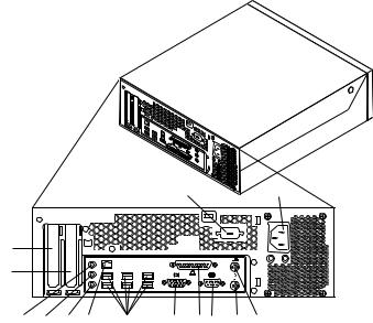
Locating connectors on the rear of your computer
Figure 2 shows the location of connectors on the rear of your computer. Some connectors on the rear of your computer are color-coded to help you determine where to connect the cables on your computer.
|
|
|
|
|
|
|
|
|
|
|
|
|
|
|
|
|
|
|
|
|
|
|
|
|
|
|
|
|
|
|
|
|
|
|
|
|
|
|
|
|
|
|
|
|
|
|
|
|
|
|
|
|
|
|
|
|
|
|
|
|
|
|
|
|
|
|
|
|
|
|
|
|
|
|
|
|
|
|
|
|
|
|
|
|
|
|
|
|
|
|
|
|
|
|
|
|
|
|
|
|
|
|
|
|
|
|
|
|
|
|
|
|
|
|
|
|
|
|
|
|
|
|
|
|
|
|
|
|
|
|
|
|
|
|
|
|
|
|
|
|
|
|
|
|
|
|
|
|
|
|
|
|
|
|
|
|
|
|
|
|
|
|
|
|
|
|
|
|
|
|
|
|
|
|
|
|
|
|
|
|
|
|
|
|
|
|
|
|
|
|
|
|
|
|
|
|
|
|
|
|
|
|
|
|
|
|
|
|
|
|
|
|
|
|
|
|
|
|
|
|
|
|
|
|
|
|
|
|
|
|
|
|
|
|
|
|
|
|
|
|
|
|
|
|
|
|
|
|
|
|
|
|
|
|
|
|
|
|
|
|
Figure 2. Connector locations |
|
|
|
|
|
|
|
|||||||||||||||||||||
1 |
|
Power cord connector |
8 |
|
Ethernet connector |
|||||||||||||||||||||||
2 |
|
Keyboard connector |
9 |
|
Microphone |
|||||||||||||||||||||||
3 |
|
Mouse connector |
10 |
Audio line-out connector |
||||||||||||||||||||||||
4 |
|
Serial connector |
11 |
Audio line-in connector |
||||||||||||||||||||||||
5 |
|
Parallel connector |
12 |
PCI Express x16 graphics adapter |
||||||||||||||||||||||||
|
|
|
|
|
|
|
|
|
|
|
|
|
|
|
|
|
|
|
|
|
|
|
|
|
|
|
|
connector |
6 |
|
VGA-monitor connector |
13 |
PCI adapter connector |
||||||||||||||||||||||||
7 |
|
USB connectors (6) |
14 |
Serial connector (some models) |
||||||||||||||||||||||||
6 ThinkCentre Hardware Installation and Replacement Guide
Connector |
Description |
USB connectors |
Used to attach a device that requires a Universal Serial Bus |
|
(USB) connection, such as a USB keyboard, USB mouse, USB |
|
scanner or USB printer. If you have more than eight USB |
|
devices, you can purchase a USB hub, which you can use to |
|
connect additional USB devices. |
Ethernet connector |
Used to attach an Ethernet cable for a local area network |
|
(LAN). |
|
Note: To operate the computer within FCC Class B limits, use |
|
a Category 5 Ethernet cable. |
Serial connector |
Used to attach an external modem, serial printer, or other |
|
devices that use a 9-pin serial connector. |
Audio line-in connector |
Used to receive audio signals from an external audio device, |
|
such as a stereo system. When you attach an external audio |
|
device, a cable is connected between the audio line-out |
|
connector of the device and the audio line-in connector of the |
|
computer. |
Audio line-out connector |
Used to send audio signals from the computer to external |
|
devices, such as powered stereo speakers (speakers with |
|
built-in amplifiers), headphones, multimedia keyboards, or the |
|
audio line-in connector on a stereo system or other external |
|
recording device. |
Chapter 2. Overview 7
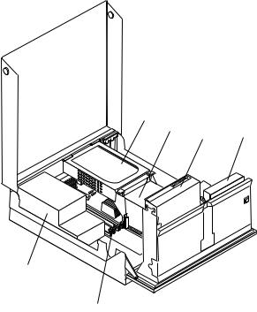
Locating components
To open the computer cover, see “Opening the cover” on page 12. Figure 3 shows the location of the various components in your computer.
|
|
|
|
|
|
|
|
|
|
|
|
|
|
|
|
|
|
|
|
|
|
|
|
|
|
|
|
|
|
|
|
|
|
|
|
|
|
|
|
|
|
|
|
|
|
|
|
|
|
|
|
|
|
|
|
|
|
|
|
|
|
|
|
|
|
|
|
|
|
|
|
|
|
|
|
|
|
|
|
|
|
|
|
|
|
|
|
|
|
|
|
|
|
|
|
|
|
|
|
|
|
|
|
|
|
|
|
|
|
|
|
Figure 3. Component locations |
|
|
|
|
|
|
|
|
|
||||
1 |
Hard disk drive |
4 |
|
Diskette drive |
|||||||||
2 |
Microprocessor and heat sink |
5 |
|
Memory connectors (2) |
|||||||||
3 |
Optical drive (such as a CD or |
6 |
|
Power-supply assembly |
|||||||||
|
DVD drive) |
|
|
|
|
|
|
|
|
|
|||
8 ThinkCentre Hardware Installation and Replacement Guide
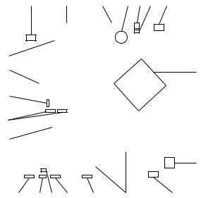
Identifying parts on the system board
Figure 4 shows the location of parts on the system board.
|
|
|
|
|
|
|
|
|
|
|
|
|
|
|
|
|
|
|
|
|
|
|
|
|
|
|
|
|
|
|
|
|
|
|
|
|
|
|
|
|
|
|
|
|
|
|
|
|
|
|
|
|
|
|
|
|
|
|
|
|
|
|
|
|
|
|
|
|
|
|
|
|
|
|
|
|
|
|
|
|
|
|
|
|
|
|
|
|
|
|
|
|
|
|
|
|
|
|
|
|
|
|
|
|
|
|
|
|
|
|
|
|
|
|
|
|
|
|
|
|
|
|
|
|
|
|
|
|
|
|
|
|
|
|
|
|
|
|
|
|
|
|
|
|
|
|
|
|
|
|
|
|
|
|
|
|
|
|
|
|
|
|
|
|
|
|
|
|
|
|
|
|
|
|
|
|
|
|
|
|
|
|
|
|
|
|
|
|
|
|
|
|
|
|
|
|
|
|
|
|
|
|
|
|
|
|
|
|
|
|
|
|
|
|
|
|
|
|
|
|
|
|
|
|
|
|
|
|
|
|
|
|
|
|
|
|
|
|
|
|
|
|
|
|
|
|
|
|
|
|
|
|
|
|
|
|
|
|
|
|
|
|
|
|
|
|
|
|
|
|
|
|
|
|
|
|
|
|
|
|
|
|
|
|
|
|
|
|
|
|
|
|
|
|
|
|
|
|
|
|
|
|
|
|
|
|
|
|
|
|
|
|
|
|
|
|
|
|
|
|
|
|
|
|
|
|
|
|
|
|
|
|
|
|
|
|
|
|
|
|
|
|
|
|
|
|
|
|
|
|
|
|
|
|
|
|
|
|
|
|
|
|
|
|
|
|
|
|
|
|
|
|
|
|
|
|
|
|
|
|
|
|
|
|
|
|
|
|
|
|
|
|
|
|
|
|
|
|
|
|
|
|
|
|
|
|
|
|
|
|
|
|
|
|
|
|
|
|
|
|
|
|
|
|
|
|
|
|
|
|
|
|
|
|
|
|
|
|
|
|
|
|
|
|
|
|
|
|
|
|
|
|
|
|
|
|
|
|
|
|
|
|
|
|
|
|
|
|
|
|
|
|
|
|
|
|
|
|
|
|
|
|
|
|
|
|
|
|
|
|
|
|
|
|
|
|
|
|
|
|
|
|
|
|
|
|
|
|
|
|
|
|
|
|
|
|
|
|
|
|
|
|
|
|
|
|
|
|
|
|
|
|
|
|
|
|
|
|
|
|
|
|
|
|
|
|
|
|
|
|
|
|
|
|
|
|
|
|
|
|
|
|
|
|
|
|
|
|
|
|
|
|
|
|
|
|
|
|
|
|
|
|
|
|
|
|
|
|
|
|
|
|
|
|
|
|
|
|
|
|
|
|
|
|
|
|
|
|
|
|
|
|
|
|
|
|
|
|
|
|
|
|
|
|
|
|
|
|
|
|
|
|
|
|
|
|
|
|
|
|
|
|
|
|
|
|
|
|
|
|
|
|
|
|
|
|
|
|
|
|
|
|
|
|
|
|
|
|
|
|
|
|
|
|
|
|
|
|
|
|
|
|
|
|
|
|
|
|
|
|
|
|
|
|
|
|
|
|
|
|
|
|
|
|
|
|
|
|
|
|
|
|
|
|
|
|
|
|
|
|
|
|
|
|
|
|
|
|
|
|
|
|
|
|
|
|
|
|
|
|
|
|
|
|
|
|
|
|
|
|
|
|
|
|
|
|
|
|
|
|
|
|
|
|
|
|
|
|
|
|
|
|
|
|
|
|
|
|
|
|
|
|
|
|
|
|
|
|
|
|
|
|
|
|
|
|
|
|
|
|
|
|
|
|
|
|
|
|
|
|
|
|
|
|
|
|
|
|
|
|
|
|
|
|
|
|
|
|
|
|
|
|
|
|
|
|
|
|
|
|
|
|
|
|
|
|
|
|
|
|
|
|
|
|
|
|
|
|
|
|
|
|
|
|
|
|
|
|
|
|
|
|
|
|
|
|
|
|
|
|
|
|
|
|
|
|
|
|
|
|
|
|
|
|
|
|
|
|
|
|
|
|
|
|
|
|
|
|
|
|
|
|
|
|
|
|
|
|
|
|
|
|
|
|
|
|
|
|
|
|
|
|
|
|
|
|
|
|
|
|
|
|
|
|
|
|
|
|
|
|
|
|
|
|
|
|
|
|
|
|
|
|
|
|
|
|
|
|
|
|
|
|
|
|
|
|
|
|
|
|
|
|
|
|
|
|
|
|
|
|
|
|
|
|
|
|
|
|
|
|
|
|
|
|
|
|
|
|
|
|
|
|
|
|
|
|
|
|
|
|
|
|
|
|
|
|
|
|
|
|
|
|
|
|
|
|
|
|
|
|
|
|
|
Figure 4. System board parts locations |
|
|
|
|
|
|
|
|
|
|
|
|
|
|
|
|
|
|
|
|
|
|
|||||||||||||
1 |
CD in connector |
12 |
Front USB2 connector |
||||||||||||||||||||||||||||||||
2 |
PCI connector |
13 |
Front USB1 connector |
||||||||||||||||||||||||||||||||
3 |
Diskette Drive connector |
14 |
BIOSWP |
||||||||||||||||||||||||||||||||
4 |
Battery |
15 |
SPI debug connector |
||||||||||||||||||||||||||||||||
5 |
Speaker connector |
16 |
COM2 connector |
||||||||||||||||||||||||||||||||
6 |
Cover presence switch (Tamper |
17 |
PSU Connector (2x12) |
||||||||||||||||||||||||||||||||
|
switch) connector |
|
|
|
|
|
|
|
|
|
|
|
|
|
|
|
|
|
|
|
|
|
|
||||||||||||
7 |
Microprocessor fan connector |
18 |
SATA connector (2) |
||||||||||||||||||||||||||||||||
8 |
Microprocessor and heat sink |
19 |
Clear CMOS/Recovery jumper |
||||||||||||||||||||||||||||||||
9 |
PSU connector (2x2) |
20 |
Front Audio connector |
||||||||||||||||||||||||||||||||
10 |
Fan connector |
21 |
PCI Express connector - Labeled on |
||||||||||||||||||||||||||||||||
|
|
|
|
|
|
|
|
|
|
|
|
|
|
|
|
|
|
|
|
system board |
|||||||||||||||
11 |
Memory connectors (2) |
|
|
|
|
|
|
|
|
|
|
|
|
|
|
|
|
|
|
|
|
|
|
||||||||||||
Chapter 2. Overview 9
10 ThinkCentre Hardware Installation and Replacement Guide
Loading...