


|
|
|
|
|
|
INSTALLATION |
|
|
|
||
|
|
|
|
|
|
INSTRUCTIONS |
|
|
|
||
|
|
|
|
|
|
|
|
DIRECT VENT |
|
|
|
|
|
|
|
|
|
|
MPD-33/35/40/45 SERIES |
||||
|
|
|
|
||||||||
This appliance may be installed in an aftermarket perma- |
|
|
VENTED GAS FIREPLACE HEATERS - DIRECT VENT MODELS |
||||||||
nently located, manufactured home (USA only) or mobile |
|
|
P/N 850,014M REV. R 06/2008 |
|
|
|
|||||
home, where not prohibited by local codes. This appliance |
|
|
|
|
|
||||||
|
|
|
|
|
|
|
|
||||
is only for use with the type of gas indicated on the rating |
|
|
|
MODELS |
|
|
|
||||
plate. This appliance is not convertible for use with other |
|
|
|
|
|
|
|||||
gases, unless a certified kit is used. |
|
|
|
|
|
|
|
|
|||
|
|
|
|
|
|
|
Millivolt Models |
Electronic Models |
|||
|
|
|
|
|
|
|
|||||
In the Commonwealth of Massachusetts: |
|
|
|
MPDT-3328CNM |
MPD-4035CNM |
MPDT-3328CNE |
MPD-4035CNE |
||||
• Installation must be performed by a licensed plumber or |
|
|
|
MPDT-3328CPM |
MPD-4035CNM-B |
MPDT-3328CPE |
MPD-4035CPE |
||||
|
|
|
MPDR-3328CNM |
MPD-4035CPM |
MPDR-3328CNE MPD-4035CNE-B |
||||||
gas fitter. |
|
|
|
||||||||
|
|
|
MPDR-3328CPM |
MPD-4540CNM |
MPDR-3328CPE |
MPD-4540CNE |
|||||
See Table of Contents for location of additional |
|
|
|
MPD-3530CNM |
MPD-4540CNM-B |
MPD-3530CNE |
MPD-4540CPE |
||||
Commonwealth of Massachusetts requirements. |
|
|
MPD-3530CNM-B |
MPD-4540CPM |
MPD-3530CPE MPD4540CNE-B |
||||||
|
|
|
|
|
|
|
MPD-3530CPM |
|
MPD-3530CNE-B |
|
|
|
|
|
|
|
|
|
|
|
|
|
|
|
|
|
|
|
|
|
|
|
|
|
|
|
WARNING:IFTHEINFORMATIONINTHISMANUAL |
|
|
|
|
|
|
|
|
|
|
|
|
|
INSTALLER: Leave this manual with the appliance. |
||||||||
|
IS NOT FOLLOWED EXACTLY, A FIRE OR EXPLO- |
|
|
||||||||
|
|
|
CONSUMER: Retain this manual for future reference. |
||||||||
|
SION MAY RESULT CAUSING PROPERTY DAM- |
|
|
||||||||
|
|
|
|
|
|
|
|
|
|
||
|
|
|
|
|
|
|
|
|
|
||
|
AGE, PERSONAL INJURY OR LOSS OF LIFE. |
|
|
|
|
|
|
|
|
|
|
|
|
|
|
|
|
|
|||||
|
|
|
|
|
|
AVERTISSEMENT: ASSUREZ-VOUS DE BIEN SUIVRE |
|
||||
|
FOR YOUR SAFETY: Do not store or use gasoline |
|
|
||||||||
|
|
LESINSTRUCTIONSDONNÉDANSCETTENOTICEPOUR |
|
||||||||
|
or other flammable vapors or liquids in the vicin- |
|
RÉDUIRE AU MINIMUM LE RISQUE D'INCENDIE OU |
|
|||||||
|
ity of this or any other appliance. |
|
POUR ÉVITER TOUT DOMMAGE MATÉRIEL, TOUTE |
|
|||||||
|
FOR YOUR SAFETY: What to do if you smell gas: |
|
BLESSURE OU LA MORT. |
|
|
|
|||||
|
|
|
|
|
|
|
|
||||
|
POUR VOTRE SÉCURITÉ: Ne pas entreposer ni utiliser |
||||||||||
|
• |
DO NOT light any appliance. |
|
||||||||
|
|
d'essence ni d'autre vapeurs ou liquides inflammables |
|||||||||
|
• |
DO NOT touch any electrical switches. |
|
||||||||
|
|
dans le voisinage de cet appareil ou de tout autre |
|||||||||
|
• |
DO NOT use any phone in your building. |
|
||||||||
|
|
appareil. |
|
|
|
|
|||||
|
• Immediately call your gas supplier from a |
|
|
|
|
|
|||||
|
|
|
|
|
|
|
|
||||
|
|
neighbor’s phone. Follow your gas suppliers |
|
POUR VOTRE SÉCURITÉ: Que faire si vous sentez une |
|||||||
|
|
instructions. |
|
odeur de gaz: |
|
|
|
|
|||
|
• If your gas supplier cannot be reached, call the |
|
|
|
|
|
|
|
|||
|
|
fire department. |
|
• Ne pas tenter d'allumer d'appareil. |
|
|
|||||
|
Installation and service must be performed by a |
|
• Ne touchez à aucun interrupteur. Ne pas vous servir |
||||||||
|
|
|
des téléphones se trouvant dans le batiment où |
||||||||
|
qualified installer, service agency or the gas |
|
|
vous vous trouvez. |
|
|
|
||||
|
supplier. |
|
• Evacuez la piéce, le bâtiment ou la zone. |
||||||||
•Appelez immédiatement votre fournisseur de gaz depuis un voisin. Suivez les instructions du
|
US |
OTL Report No. 116-F-13-4 |
fournisseur. |
|
|||
|
|
|
• Si vous ne pouvez rejoindre le fournisseur de gaz, |
|
|||
|
|
||||||
|
|
|
|
|
|
||
|
|
|
|
|
|
||
|
|
|
|
|
|
||
A French manual is available upon request. Order Form Number |
appelez le service dos incendies. |
|
|||||
|
|
||||||
850,014CF. |
L'installation et service doit être exécuté par un qualifié |
|
|||||
Ce manuel d’installation est disponible en francais, simplement |
|
||||||
installeur, agence de service ou le fournisseur de gaz. |
|
||||||
en faire la demande. Numéro de la pièce 850,014CF. |
1 |
||||||
|
|||||||
|
|
|
NOTE: DIAGRAMS & |
ILLUSTRATIONS NOT TO SCALE. |
|||
|
|||||||
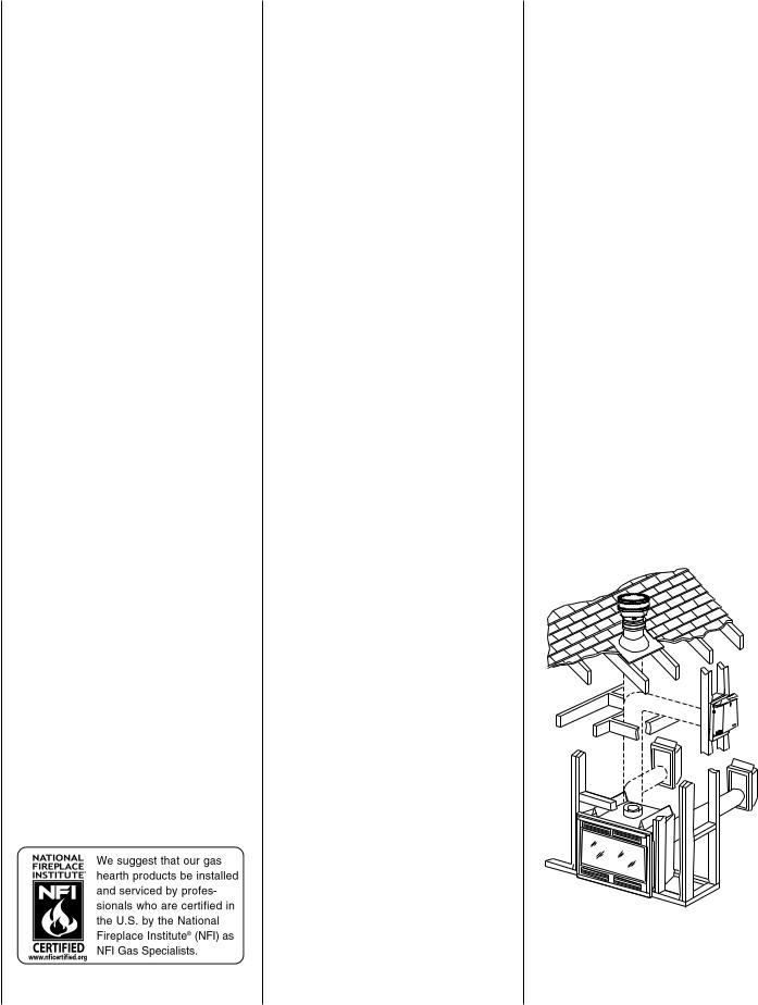
TABLE OF CONTENTS |
|
|
|
Packaging ........................................ |
page |
2 |
|
Introduction ..................................... |
page |
2 |
|
General Information ......................... |
page |
2 |
|
Location |
.......................................... |
page |
4 |
Appliance and Vent Clearances ....... |
page |
4 |
|
Vent Termination Clearances ........... |
page |
5 |
|
Typical Installation Sequence .......... |
page |
5 |
|
Detailed Installation Steps ............... |
page |
6 |
|
Step 1. |
Framing ............................. |
page |
6 |
Step 2. Routing Gas Line ............... |
page |
6 |
|
Fireplace Specifications ................... |
page |
9 |
|
Step 3. Install the Venting System . page |
9 |
||
Requirements for Commonwealth |
|
|
|
of Massachusetts .......................... |
page |
9 |
|
Vertical Termination Systems .......... |
page |
11 |
|
Vent Section Length Chart ............... |
page |
11 |
|
Vertical Vent Tables and Figures ...... |
page |
11 |
|
Horizontal Termination System ........ |
page |
16 |
|
Horizontal Vent Tables and Figures . page |
18 |
||
Venting Using Flexible Vent Pipe ..... |
page |
21 |
|
Step 4. |
Field Wiring ....................... |
page |
22 |
Step 5. Optional Blower Kit Wiring |
page |
22 |
|
Step 6. Connecting Gas Line .......... |
page |
23 |
|
Step 7. |
Installing Logs ................... |
page |
24 |
Step 8. |
Checking Unit Operation ..... |
page |
24 |
Step 9. Installing Glass Door ......... |
page |
24 |
|
Step 10. Burner Adjustments ........... |
page |
25 |
|
Step 11. Hood Installation ............... |
page |
25 |
|
Finishing Requirements ................... |
page |
25 |
|
Cold Climate Insulation .................... |
page |
26 |
|
Installation Accessories ................... |
page |
27 |
|
Gas Conversion Kits .................. |
page 29 |
||
This installation manual will help you obtain a safe, efficient, dependable installation for your appliance and vent system.
Please read and understand these instructions before beginning your installation.
2 |
NOTE: DIAGRAMS & ILLUSTRATIONS NOT TO SCALE. |
PACKAGING
The assembled vented gas fireplace heater is packaged with:
1 - one log set located in firebox area.
2 - one envelope containing the literature package which consists of the homeowner's manual, installation instructions, log set supplement and warranty; envelope is located in the control area.
3 - one vent restrictor to be applied as shown on page 10; restrictor is taped to the envelope.
4 - one hood located behind the top panel.
5 - one bag of decorative volcanic stone located in the control area.
6 - one bag of glowing embers located in the control area.
7 - one bag of vermiculite located in control area.
INTRODUCTION
These fireplaces are designed, tested and listed for operation and installation with, and only with, Secure Vent™ Direct Vent System Components, Secure Flex™ Flexible Vent Components manufactured by Security Chimneys International and Z-Flex™ Model GA Venting Systems, listed to UL1777 and ULCS635 manufactured by Flexmaster Canada Limited. These approved vent system components are labeled for identification. DO NOT use any other manufacturer's vent components with these appliances.
Millivolt appliances are designed to operate on natural or propane gas. A millivolt gas control valve with piezo ignition system provides safe, efficient operation. External electrical power is required to operate the optional blower if installed in these units.
Electronic appliances are designed to operate on natural or propane gas. An electronic intermittent pilot ignition system provides safe, efficient operation. External electrical power is required to operate these units.
These appliances comply with National Safety Standards and are tested and listed by OmniTest Laboratories (Report No. 116-F-13-4) to ANSI Z21.88 (in Canada, CSA-2.33), and CAN/ CGA-2.17-M91 in both USA and Canada, as vented gas fireplace heaters.
Both millivolt and electronic versions of these appliances are listed by Omni-Test Laboratories for installation in bedrooms and mobile homes.
Installation must conform to local codes. In the absence of local codes, installation must comply with the current National Fuel Gas Code, ANSI Z223.1. (In Canada, the current CAN-1
B149 installation code.)
NOTE: DIAGRAMS & ILLUSTRATIONS NOT TO SCALE.
Electrical wiring must comply with the National Electrical Code ANSI/ NFPA 70 - (latest edition). (In Canada, the current CSA C22-1 Canadian Electrical Code.)
DO NOT ATTEMPT TO ALTER OR MODIFY THE CONSTRUCTION OF THE APPLIANCE OR ITS COMPONENTS. ANY MODIFICATION OR ALTERATION MAY VOID THE WARRANTY, CERTIFICATION AND LISTINGS OF THIS UNIT.
GENERAL INFORMATION
Note: Installation and repair should be performed by a qualified service person. The appliance should be inspected annually by a qualified professional service technician. More frequent inspections and cleanings may be required due to excessive lint from carpeting, bedding material, etc. It is imperative that the control compartment, burners and circulating air passage ways of the appliance be kept clean.
S'assurer que le brùleur et le compartiment des commandes sont propres. Voir les instructions d'installation et d'utilisation qui accompagnent l'appareil.
Provide adequate clearances around air openings and adequate accessibility clearance for service and proper operation. Never obstruct the front openings of the appliance.
These appliances are designed to operate on natural or propane gas only.
TYPICAL INSTALLATION
Figure 1
Millivolt Models -
Millivolt models come standard with the manu- ally-modulated gas valve; flame appearance and heat output can be controlled at the gas valve.
Input of millivolt models is shown in the following table:
Millivolt Models with
Manually-Modulated Gas Valve
Natural Gas
Model Series |
Input rate (BTU/H) |
|
|
|
|
MPDT-3328 |
11,700 to 17,500 |
|
MPDR-3328 |
||
|
||
MPD-3530 |
12,800 to 20,000 |
|
|
|
|
MPD-4035 |
18,500 to 27,000 |
|
|
|
|
MPD-4540 |
20,500 to 29,000 |
|
|
|
Millivolt Models with
Manually-Modulated Gas Valve
Propane Gas
Model Series |
Input rate (BTU/H) |
|
|
|
|
MPDT-3328 |
14,000 to 17,500 |
|
MPDR-3328 |
||
|
||
MPD-3530 |
15,200 to 20,000 |
|
|
|
|
MPD-4035 |
21,500 to 27,000 |
|
|
|
|
MPD-4540 |
22,500 to 29,000 |
|
|
|
Electronic Models -
Electronic models have a fixed rate gas valve. Input of electronic models is shown in the following table:
Electronic Models with Fixed-Rate Gas Valve
Natural and Propane Gas
Model Series |
Input rate (BTU/H) |
|
MPDT-3328 |
17,500 |
|
MPDR-3328 |
||
|
||
MPD-3530 |
20,000 |
|
MPD-4035 |
27,000 |
|
MPD-4540 |
29,000 |
All Models -
Maximum manifold pressure is 3.5 in. w.c. (0.87 kPa) for natural gas and 10 in. w.c. (2.49 kPa) for LP/Propane gas.
Installations at Altitudes of 0 to 4500 ft.- Units are tested and approved for elevations of 0 to 4500 feet (0 to 1372 meters).
Installations at Altitudes above 4500 ft.- For elevations above 4500 feet (1372 meters), install the unit according to the regulations of the local authorities having jurisdiction and, in the USA, the latest edition of the National Fuel Gas Code (ANSI Z223.1) or, in Canada, the latest edition of the CAN1-B149.1 and .2 codes.
Table 1 shows the units' gas orifice size for the elevations indicated.
The millivolt appliances are manually controlled and feature a spark ignitor (piezo) that allows the appliance's pilot gas to be lit without the use of matches or batteries. This system provides continued service in the event of a power outage.
Model |
Orifice size |
Elevation |
||
|
|
Feet |
||
Series |
|
|
||
|
|
(meters) |
||
|
Nat. |
Prop. |
||
|
|
|||
|
|
|
|
|
MPDT-3328 |
#45 |
0.048 inch |
|
|
MPDR-3328 |
|
|||
|
|
|
||
|
|
|
0-4500 |
|
MPD-3530 |
#44 |
#55 |
||
|
|
|
(0-1370) |
|
MPD-4035 |
#37 |
0.062 inch |
||
|
||||
|
|
|
|
|
MPD-4540 |
#36 |
#52 |
|
|
|
|
|
|
|
Table 1
Do not use these appliances if any part has been under water. Immediately call a qualified, professional service technician to inspect the appliance and to replace any parts of the control system and any gas control which have been under water.
Ne pas se servir de cet appareil s'il a été plongé dans l'eau, complètement ou en partie. Appeler un technicien qualifié pour inspecter l'appareil et remplacer toute partie du système de contrôle et toute commande qui ont été plongés dans l'eau.
This appliance may be installed in an aftermarket permanently located, manufactured home (USA only) or mobile home, where not prohibited by local codes. This appliance is only for use with the type of gas indicated on the rating plate. This appliance is not convertible for use with other gases, unless a certified kit is used.
Cet appareil peut être installé dans un maison préfabriquée (É.-U. seulement) ou mobile déjà installée à demeure si les réglements locaux le permettent.
Cet appareil doit être utilisé uniquement avec les types de gaz indiqués sur la plaque signalétique. Ne pas l'utiliser avec d'autres gaz sauf si un kit de conversion certifié est installé.
Test gage connections are provided on the front of the millivolt gas control valve (identified IN for the inlet and OUT for the manifold side). A 1/8" NPT test gage connection is provided at the inlet and outlet side of the electronic gas control valve.
Minimum inlet gas pressure to these appliances is 5.0 inches water column (1.24 kPa) for natural gas and 11 inches water column (2.74 kPa) for propane for the purpose of input adjustment.
Maximum inlet gas supply pressure to these appliances is 10.5 inches water column (2.61 kPa) for natural gas and 13.0 inches water column (3.23 kPa) for propane.
NOTE: DIAGRAMS & ILLUSTRATIONS NOT TO SCALE.
These appliances must be isolated from the gas supply piping system (by closing their individual manual shut-off valve) during any pressure testing of the gas supply piping system at test pressures equal to or less than 1/2 psig (3.5 kPa).
Theseappliancesandtheirindividualshut-offvalves must be disconnected from the gas supply piping system during any pressure testing of that system at pressures in excess of 1/2 psig (3.5 kPa).
These appliances must not be connected to a chimney or flue serving a separate solid fuel burning appliance.
These heater rated appliances are intended for use as supplemental heaters only.
Carbon Monoxide Poisoning: Early signs of carbon monoxide poisoning are similar to the flu with headaches, dizziness and/or nausea. If you have these signs, obtain fresh air immediately. Turn off the gas supply to the appliance and have it serviced by a qualified professional, as it may not be operating correctly.
WARNING: FAILURE TO COMPLY WITH THE INSTALLATION AND OPERATING INSTRUCTIONS PROVIDED IN THIS DOCUMENT WILL RESULT IN AN IMPROPERLY INSTALLED AND OPERATING APPLIANCE, VOIDING ITS WARRANTY. ANY CHANGE TO THIS APPLIANCE AND/ OR ITS OPERATING CONTROLS IS DANGEROUS. IMPROPER INSTALLATION OR USE OF THIS APPLIANCE CAN CAUSE SERIOUS INJURY OR DEATH FROM FIRE, BURNS, EXPLOSION OR CARBON MONOXIDE POISONING.
WARNING: CHILDREN AND ADULTS SHOULD BE ALERTED TO THE HAZARDS OF HIGH SURFACE TEMPERATURES. USE CAUTION AROUND THE APPLIANCE TO AVOID BURNS OR CLOTHING IGNITION. YOUNG CHILDREN SHOULD BE CAREFULLY SUPERVISED WHEN THEY ARE IN THE SAME ROOM AS THE APPLIANCE.
WARNING: DO NOT PLACE CLOTHING OR OTHER FLAMMABLE MATERIALS ON OR NEAR THIS APPLIANCE.
AVERTISSEMENT: SURVEILLER LES ENFANTS. GARDER LES VÊTEMENTS, LES MEUBLES, L'ESSENCE OU AUTRES LIQUIDES À VAPEUR INFLAMMABLES À COTE DE L'APPAREIL.
3
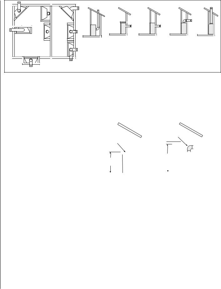
TOP |
|
VENTREAR |
APPLICATION |
|
REAR |
|
|
|
|
|
|
VENT |
|
|
|
APPLICATION |
|
|
|
|
|
||
APPLICATION |
|
|
|
|
VENT |
|
|
|
|
|
|
|
|
|
|
|
|
|
|
|
|
|
|
TOP VENT |
|
TOPVENT |
APPLICATION |
TOPVENT |
APPLICATION |
|
HORIZONTAL VENT |
HORIZONTAL VENT |
HORIZONTAL VENT |
VERTICAL VENT |
|
APPLICATION |
|
|
|
|
|
|
|
|
|
|
|
|
|
|
|
|
VENTTOP |
APPLICATION |
VERTICAL VENT |
(Rear Vent Application |
(Rear Vent Application |
(Top Vent |
(Top Vent |
|
|
|
|
|
(Rear Vent |
||||||
|
|
|
|
|
|
|
|||||
|
|
|
|
|
|
|
without a chase) |
With a chase) |
Application) |
Application) |
|
|
|
|
|
|
|
|
Application) |
||||
|
|
|
|
|
|
|
|
|
|
|
|
|
RECESSED |
|
|
|
|
|
|
|
|
||
|
INSTALLATION |
|
|
|
|
|
|
|
|
||
|
|
|
|
TOP VENT |
|
|
Typical Locations |
|
|
|
|
|
|
|
|
APPLICATION |
|
|
|
|
|
|
|
Figure 2
|
LOCATION |
|
|
|
|
|
|
|
|
|
|
|
|
|
|
|
|
|
|
|
|
|
|
|
|
In selecting the location, the aesthetic and |
|
|
|
|
Model No. |
|
|
|
|
|
|
|
Shelf Height inches (mm) |
|
|
|
|
||||||
|
functional use of the appliance are primary |
|
|
|
|
|
|
|
|
|
|
|
|
|
|
|
|
|
|
|
|
|
||
|
|
|
|
|
Top Vent - with One 90 Degree Elbow |
Rear Vent - Straight Out the Back |
|
|||||||||||||||||
|
|
|
|
|
|
|
|
|||||||||||||||||
|
concerns. However, vent system routing to the |
|
|
|
|
|
|
|
||||||||||||||||
|
|
|
|
|
|
|
|
|
|
|
|
|
|
|
|
|
|
|
|
|
|
|
|
|
|
|
|
|
|
|
|
Secure Vent |
|
|
|
Secure Flex |
|
Secure Vent |
Secure Flex |
|
|||||||||
|
exterior and access to the fuel supply are also |
|
|
|
|
|
|
|
|
|
||||||||||||||
|
|
|
|
|
MPDT-3328 |
44 1/2 (1130) |
|
|
|
46 1/4 (1175) |
|
N/A |
|
N/A |
|
|||||||||
|
important. Due to high temperatures the |
|
|
|
|
|
|
|
|
|
|
|||||||||||||
|
appliance should be located out of traffic |
|
|
|
|
MPDR-3328 |
|
N/A |
|
|
|
N/A |
33 1/4 (845) |
33 1/4 (845) |
|
|||||||||
|
and away from furniture and draperies. |
|
|
|
|
MPD-3530 |
46 1/2 (1181) |
|
|
|
48 1/4 (1226) |
35 1/4 (895) |
35 1/4 (895) |
|
||||||||||
|
Consideration should be given to traffic ways, |
|
|
|
|
MPD-4035 |
51 1/2 (1308) |
|
|
|
53 1/4 (1353) |
40 1/4 (1022) |
40 1/4 (1022) |
|
||||||||||
|
furniture, draperies, etc., due to elevated sur- |
|
|
|
|
MPD-4540 |
|
|
|
|
||||||||||||||
|
|
|
|
|
|
|
|
|
|
|
|
|
|
|
|
|
|
|
|
|
|
|||
|
face temperatures (Figure 2 ). The location |
|
|
|
|
|
|
|
|
|
|
|
|
|
|
|
|
|
|
|
|
|
|
|
|
should also be free of electrical, plumbing or |
|
|
|
|
|
|
|
|
|
|
|
|
|
|
|
Do not insulate the |
|
|
|
|
|||
|
other heating/air conditioning ducting. |
|
|
|
|
Do not insulate the |
|
|
|
|
|
space between the |
|
|
|
|
||||||||
|
These direct vent appliances are uniquely suited |
|
|
|
|
space between the |
|
|
|
|
|
appliance and the |
|
|
|
|
||||||||
|
|
|
|
|
appliance and the |
|
|
|
|
|
area above it. |
|
|
|
|
|||||||||
|
for installations requiring a utility shelf posi- |
|
|
|
|
|
area above it. |
|
|
|
|
|
|
|
|
|
|
|
|
|
||||
|
|
|
|
|
|
|
|
|
|
|
|
|
|
|
|
|
|
|
||||||
|
tioned directly above the fireplace. Utility shelves |
|
|
|
|
|
|
|
|
|
|
|
|
|
|
|
|
|
|
|
|
|
|
|
|
like these are commonly used for locating tele- |
|
|
|
|
|
|
|
|
|
|
|
|
|
|
|
|
|
|
|
|
|
|
|
|
|
|
|
|
|
|
|
|
|
|
|
|
|
|
|
|
|
|
|
|
|
|
|
|
|
vision sets and decorative plants. |
|
|
|
|
|
|
|
|
|
|
|
|
|
|
|
Shelf Height |
|
|
|
|
|
||
|
|
|
|
|
|
|
|
|
|
|
|
|
|
|
|
|
|
|
|
|
||||
|
To provide for the lowest possible shelf surface |
|
|
|
|
|
Shelf Height |
|
|
|
|
|
|
(see table) |
|
|
|
|
|
|||||
|
|
|
|
|
|
(see table) |
|
|
|
|
|
|
|
|
|
|
|
|
|
|
||||
|
use the alternate rear vent outlet with attached |
|
|
|
|
|
|
|
|
|
|
|
|
|
|
|
|
|
|
|
|
|
|
|
|
venting routed in a way to minimize obstruc- |
|
|
|
|
|
|
|
|
|
|
|
|
|
|
|
|
|
|
|
|
|
|
|
|
|
|
|
|
|
|
|
|
|
|
|
|
|
|
|
|
|
|
|
|
|
|
|
|
|
tions to the use of the space above the appli- |
|
|
|
|
|
|
|
|
|
|
|
|
|
|
|
|
|
|
|
|
|
|
|
|
|
|
|
|
|
|
|
|
|
|
|
|
|
|
|
Shelf Above Fireplace With Top Venting |
||||||||
|
|
|
|
|
Shelf Above Fireplace With Rear Venting |
|||||||||||||||||||
|
ance. Do not insulate the space between the |
|
|
|
|
|||||||||||||||||||
|
appliance and the area above it. See Figure 3. |
|
|
Figure 3 |
|
|
|
|
|
|
|
|
|
|
|
|
|
|
|
|
|
|||
|
The minimum height from the base of the appli- |
|
|
|
|
|
|
|
|
|
|
|
|
|
|
|
|
|
|
|
|
|
|
|
|
|
|
|
|
|
|
|
|
|
|
|
|
|
|
|
|
|
|
|
|
|
|
|
|
|
ance to the underside of combustible materials |
|
|
|
|
|
|
|
|
|
|
|
|
|
|
|
|
|
|
|
|
|
|
|
|
|
|
|
|
|
|
|
|
|
|
|
|
|
|
|
|
|
|
|
|
|
|
|
|
|
used to construct a utility shelf in this fashion is |
|
|
|
|
|
|
|
|
|
|
|
|
|
|
|
|
|
|
|
|
|
|
|
|
|
|
|
|
|
|
1/2 in. (13 mm) |
|
|
|
|
|
|
|
|
|
|
|||||||
|
shown in the table in Figure 3. |
|
|
|
|
BACK |
|
|
|
|
|
|
|
|
|
|
||||||||
|
|
|
|
|
0 in. (0 mm) spacers |
|
|
|
|
|
|
|
|
|
||||||||||
|
The appliance should be mounted on a fully |
|
|
|
|
|
|
|
|
|
|
|
|
|
|
|
||||||||
|
|
|
|
|
|
|
|
|
|
|
|
|
|
|
|
|
|
|
|
|
|
|
|
|
|
|
|
|
|
|
|
1/2 in. (13 mm)** |
|
*Note: 3 in. (75 mm) above any horizontal/ |
|||||||||||||||
|
supported base extending the full width and |
|
|
|
|
SIDES |
|
|||||||||||||||||
|
depth of the unit. The appliance may be located |
|
|
|
|
|
|
0 in. (0 mm) spacers |
|
inclined vent component. |
|
|
|
|
||||||||||
|
on or near conventional construction materi- |
|
|
|
TOP SPACERS |
|
0 in. (0 mm) |
|
|
**Note: See page 5, step 1 for clearance |
||||||||||||||
|
als. However, if installed on combustible mate- |
|
|
|
|
|
|
|||||||||||||||||
|
|
|
|
|
|
|
|
|
|
|
|
|
|
|
|
|||||||||
|
rials, such as carpeting, vinyl tile, etc., a metal |
|
|
|
|
FLOOR |
|
0 in. (0 mm) |
|
|
requirements to the nailing flange located |
|||||||||||||
|
or wood barrier covering the entire bottom |
|
|
|
|
|
|
|
|
|
|
|
|
|
|
|
at each side of the unit and any screw |
|||||||
|
|
|
|
From Bottom |
|
|
|
|
|
|
|
|
|
|||||||||||
|
surface must be used. |
|
|
|
64 in. (1626 mm) |
|
heads adjacent to it. |
|
|
|
|
|||||||||||||
|
APPLIANCE AND VENT CLEARANCES |
|
|
|
|
of Unit to |
|
|
|
|
|
|
|
|
|
|||||||||
|
|
|
|
|
Ceiling |
|
|
|
|
|
|
|
|
|
|
|
|
|
|
|
|
|
||
|
The appliance is approved with zero clearance |
|
|
|
|
|
|
|
|
|
|
|
|
|
|
|
|
|
|
|
|
|
|
|
|
|
|
|
|
VENT |
1 in. (25.4 mm)* |
|
|
|
|
|
|
|
|
|
|
||||||||
|
to combustible materials on all sides (as de- |
|
|
|
|
|
|
|
|
|
|
|
|
|
|
|||||||||
|
tailed in Table 2 ), with the following exception: |
|
|
|
|
|
|
|
|
|
|
|
|
|
|
|
|
|
|
|
|
|
|
|
|
|
|
|
|
SERVICE CLEARANCES |
|
|
|
|
|
|
|
|
|
|
|||||||||
|
When the unit is installed with one side flush |
|
|
|
|
|
|
|
|
|
|
|
|
|
|
|||||||||
|
|
|
|
|
|
|
|
|
|
|
|
|
|
|
|
|
|
|
|
|
|
|
|
|
|
with a wall, the wall on the other side of the unit |
|
|
|
|
FRONT |
3 Feet. (0.9 meters) |
|
|
|
|
|
|
|
|
|
||||||||
|
must not extend beyond the front edge of the |
|
|
|
|
|
|
|
|
|
|
|
|
|
||||||||||
|
|
|
|
|
|
|
|
|
|
|
|
|
|
|
|
|
|
|
|
|
|
|
|
|
|
|
|
|
|
|
|
|
|
|
|
|
|
|
|
|
|
|
|
|
|
|
|
|
|
|
unit. In addition, when the unit is recessed, the |
|
|
Table 2 |
|
|
|
|
|
|
|
|
|
|
|
|
|
|
|
|
|
|||
|
side walls surrounding the unit must not extend |
|
|
|
|
|
|
|
|
|
|
|
|
|
|
|
|
|
|
|
|
|
|
|
|
|
|
|
|
|
|
|
|
|
|
|
|
|
|
|
|
|
|
|
|
|
|
|
|
4 |
beyond the front edge of the unit. See Figure 2. |
|
|
|
NOTE: DIAGRAMS & ILLUSTRATIONS NOT TO SCALE. |
|
|
|
|
|
|
|
|
|||||||||||
|
|
|
|
|
|
|
|
|
||||||||||||||||
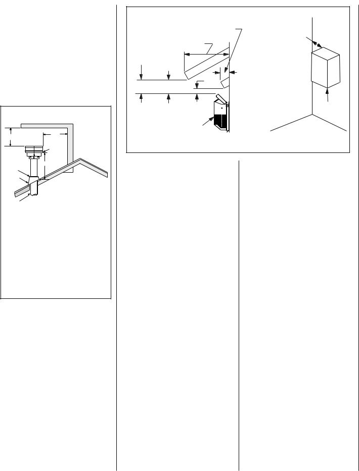
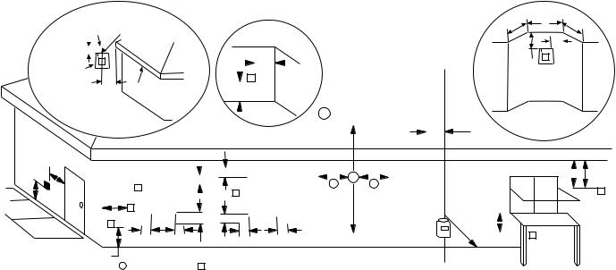
VENT TERMINATION CLEARANCES
These instructions should be used as a guideline and do not supersede local codes in any way. Install vent according to local codes, these instructions, the current National Fuel Gas Code (ANSI-Z223.1) in the USA or the current standards of CAN/CGA-B149.1 and - B149.2 in Canada.
Vertical Vent Termination Clearances
Terminate single vent caps relative to building components according to Figure 4.
TERMINATION HEIGHTS FOR VENTS ABOVE FLAT OR SLOPED ROOFS
Horizontal Overhang
2 FT MIN.
Vent
Termination
Storm Collar
Flashing
Concentric
Vent Pipe
2 FT |
Vertical |
MIN. |
Wall |
|
|
Lowest |
|
Discharge |
|
Opening |
|
H* |
|
|
X |
|
12 |
Roof Pitch is X/12 |
|

 1 inch (25.4 mm) Minimum Clearance to Combustibles
*H = MINIMUM HEIGHT FROM ROOF TO LOWEST DISCHARGE OPENING OF VENT
Roof Pitch |
H |
|
(feet) |
||
|
||
Flat to 6/12 |
1.0 |
|
Over 6/12 to 7/12 |
1.25 |
|
Over 7/12 to 8/12 |
1.5 |
|
Over 8/12 to 9/12 |
2.0 |
|
Over 9/12 to 10/12 |
2.5 |
|
Over10/12 to 11/12 |
3.25 |
|
Over 11/12 to 12/12 |
4.0 |
Figure 4
Terminate multiple vent terminations according to the installation codes listed on this page.
|
|
Horizontal Vent Termination Clearances |
|
|
|
Combustible Projection |
All horizontal terminations |
|
|
2-1/2 inches or less in length |
may be located as close |
|
Combustible Projection |
as 6” (152mm) to any |
|
|
(non-combustible and |
||
greater than 2-1/2 inches in length |
combustible) exterior |
||
|
|
|
sidewall. This distance |
Ventilated |
|
|
may be decreased to |
Soffit |
Unventilated |
2” (51mm) for non- |
|
|
combustible exterior |
||
|
|
Soffit |
|
|
|
sidewalls only, if the |
|
|
|
|
|
|
|
3" |
SV4.5HT-2 termination |
|
|
is used. |
|
|
|
(76 mm) |
|
18" |
|
12" |
Termination Kit |
|
|
||
(457 mm) |
|
(305 mm) |
|
|
|
Termination Kit |
|
Figure 5 - |
Side Elevation View |
|
|
Horizontal Vent Termination Clearances
The horizontal vent termination must have a minimum of 3" (76 mm) clearance to any overhead combustible projection of 2-1/2" (64 mm) or less. See Figure 5. For projections exceeding 2-1/2" (64 mm), see Figure 5. All horizontal terminations may be located as close as 6" (152mm) to any (non-combustible and combustible) exterior sidewall. This distance may be decreased to 2" (51mm) for non-combus- tible exterior sidewalls only, if the SV4.5HT-2 termination is used. For additional vent location restrictions refer to Figure 8 on page 7.
TYPICAL INSTALLATION SEQUENCE
The typical sequence of installation follows, however, each installation is unique resulting in variations to those described.
See the page numbers references in the following steps for detailed procedures.
Step 1. (page 6) Construct the appliance framing. Position the appliance within the framing and secure with nailing brackets.
Step 2. (page 6) Route gas supply line to appliance location.
Step 3. (page 9) Install the vent system and exterior termination.
Step 4. (page 22) Field Wiring
a.Millivolt Appliances – Install the operating control switch (not factory provided) and bring in electrical service line for forced air circulating blower (optional equipment).
b.Electronic Appliances – Field wire and install operating control switch.
Step 5. (page 22) Install blower kit (optional equipment).
Step 6. (page 23) Make connection to gas supply.
Step 7. (page 24) Install the logs, decorative volcanic stone and glowing embers.
Step 8. (page 24) Checkout appliance operation.
Step 9. (page 24) Install glass door frame assembly.
Step 10. (page 25) Adjust burner to ensure proper flame appearance.
Step 11. (page 25) Install the hoods.
NOTE: DIAGRAMS & ILLUSTRATIONS NOT TO SCALE. |
5 |
DETAILED INSTALLATION STEPS
The appliance is shipped with all gas controls and components installed and pre-wired. Remove the shipping carton, exposing the front glass door. Remove the top panel. Remove the cardboard from underneath the pressure relief plates. Press in simultaneously the left and right side of the bottom hinged panel, to release it. Lower the bottom hinged panel. Open the two latches (located under the firebox floor) securing the glass door. Remove the door by tilting it outward at the bottom and lifting it up. Set the door aside protecting it from inadvertent damage. See Figure 53 on page 24.
Step 1. FRAMING
Frame these appliances as illustrated in Figure 9 on page 8, unless the appliance is to be installed in a corner. See Figure 10 on page 8 for corner framing installations. All framing details must allow for a minimum clearance to combustible framing members as shown in
Table 2.
If the appliance is to be elevated above floor level, a solid continuous platform must be constructed.
Headers may be in direct contact with the appliance top spacers but must not be supported by them or notched to fit around them. All construction above the appliance must be self supporting. DO NOT use the appliance for structural support.
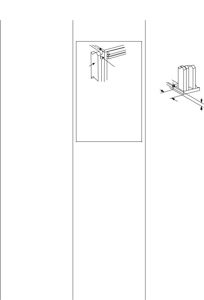
The fireplace should be secured to the side framing members using the unit's nailing flanges - one top and bottom on each side of the fireplace front. See Figure 6. Use 8d nails or their equivalent.
Side |
Unit Nailing Flange |
|
(No clearance to |
||
Framing |
||
combustible |
||
|
framing is required) |
|
Left Side Front Corner of Fireplace Shown |
||
(Right Side Requirements the Same) |
||
Unit Being Secured By Its Nailing Flanges |
||
|
To The Framing |
|
Note: The nailing flanges, combustible members |
||
and screw heads located in areas directly adjacent |
||
to the nailing flanges, are EXEMPT from the 1/2” |
||
clearance to combustible requirements for the |
||
firebox outer wrapper. Combustible framing may be |
||
in direct contact with the nailing flanges and may |
||
be located closer than 1/2” from screw heads and |
||
the firebox wrapper in areas adjacent to the nailing |
||
flanges. Frame the opening to the exact dimensions |
||
specified in the framing details of this manual. |
||
Figure 6
Step 2. ROUTING GAS LINE
Route a 1/2" (13 mm) gas line along the inside of the right side framing as shown in Figure 7. Gas lines must be routed, constructed and made of materials that are in strict accordance with local codes and regulations. All appliances are factory-equipped with a flexible gas line connector and 1/2 inch shutoff valve. (See step 6 on page 23).
Right Side
Front Corner of
Fireplace Framing
3" (76 mm)
6-1/2" (152 mm)
Figure 7
6 |
NOTE: DIAGRAMS & ILLUSTRATIONS NOT TO SCALE. |
|
|
|
|
EXTERIOR HORIZONTAL VENT TERMINATION CLEARANCE REQUIREMENTS |
|
|
|
|
|
|
|
|
|
|
|
|
|
|
|
||||||||||||||||||||||||||||||||||||||||||||||||||
|
|
|
|
|
|
|
|
|
|
|
|
|
|
|
|
|
|
|
|
|
|
|
|
|
|
|
|
|
|
|
|
|
|
|
|
|
NOTE: Local Codes Or Regulations |
|
|
|
|
|
|
|
|
|
|
|
|
|
|
|
|
|
|
|
|
|
|
|
|||||||||
* See Item D in the Text Below. |
|
|
|
|
|
|
|
|
|
|
|
|
|
|
|
|
|
|
|
May Require Different Clearances. |
|
|
|
|
|
|
|
|
|
|
|
|
|
|
|
|
|
|
|
|
|
|
|
||||||||||||||||||||||||||
|
|
|
|
|
|
|
|
|
|
|
|
|
|
|
|
|
|
|
NOTE: Location Of The Vent Termination |
N |
|
P |
N |
|
|||||||||||||||||||||||||||||||||||||||||||||
Exterior Wall |
|
Center Line |
|
|
|
|
|
|
|
|
|
Inside |
|
|
|
|
|
|
|||||||||||||||||||||||||||||||||||||||||||||||||||
|
|
|
|
|
|
|
|
|
|
|
|
|
|
|
|
|
|
|
|
|
|
|
|
|
|
|
|
|
|
|
|
|
|||||||||||||||||||||||||||||||||||||
|
|
|
|
|
|
|
|
|
of Termination |
|
|
|
|
|
|
|
Corner Detail |
|
|
|
|
Must Not Interfere With Access To The |
|
|
|
|
|
|
|
O |
|
|
|
|
|
|
|
|
|
|
|||||||||||||||||||||||||||||
|
|
|
|
|
|
|
|
|
|
|
|
|
|
|
|
|
|
|
|
|
|
|
|
|
|
|
|
|
Electrical Service. |
|
|
|
|
|
|
|
|
|
|
|
|
|
|
|
|
|
|
|
|
||||||||||||||||||||
|
|
|
|
|
|
|
|
|
|
|
|
|
|
|
|
|
|
|
|
|
|
|
|
|
|
|
|
|
|
|
|
|
|
|
|
|
|
|
|
|
|
|
|
|
|
|
|||||||||||||||||||||||
|
|
*18” |
|
|
|
|
|
|
|
|
|
|
|
|
|
|
|
|
|
|
|
|
|
|
|
|
|
|
|
|
|
|
|
|
|
|
|
|
|
|
|
|
|
|
|
|
|
|
|
|
|
|
|
|
|
|
|
|
|
|
|
|
|
|
|||||
|
|
|
|
|
|
|
|
|
|
|
|
|
|
|
|
|
|
|
|
|
|
|
|
|
|
|
|
|
|
|
|
|
|
|
|
|
|
|
|
|
|
|
|
|
|
|
|
|
|
|
|
|
|
|
|
V |
|
|
|
|
|
|
|
|
|
|
|||
Horizontal |
|
|
V |
|
|
|
|
|
|
|
|
|
|
|
|
|
|
|
|
|
|
|
|
|
|
G |
|
|
|
|
|
|
|
|
|
|
|
|
|
|
|
|
|
|
|
|
|
|
Q |
|
|
|
|
|
|
|
|
||||||||||||
|
|
|
|
|
|
|
|
|
|
|
|
|
|
|
|
|
|
|
|
|
|
|
|
|
|
|
|
|
|
|
|
|
|
|
|
|
|
|
|
|
|
|
|
|
|
|
|
|
|
|
|
|
|
|
|
|
|
|
|||||||||||
|
|
|
|
|
|
|
|
|
|
|
|
|
|
|
|
|
|
|
|
|
|
|
|
|
|
|
|
|
|
|
|
|
|
|
|
|
|
|
|
|
|
|
|
|
|
|
|
|
|
|
|
|
|
|
|
|
|
|
|
|
|
||||||||
Termination |
|
|
|
|
|
|
|
|
|
|
|
|
|
|
|
|
|
|
V |
|
|
|
|
|
|
|
|
|
|
|
|
|
|
|
|
|
|
|
|
|
|
|
|
|
|
|
|
|
|
|
|
|
|
|
|
|
|
|
|
|
|
||||||||
|
|
|
|
|
|
18” |
|
|
Ventilated Soffit |
|
|
|
|
|
|
|
|
|
|
|
|
|
|
|
|
|
|
|
|
|
|
|
|
|
|
|
|
|
|
|
|
|
|
|
|
|
|
|
|
|
|
|
|
|
|
|
|
|
|
|
|||||||||
|
|
|
|
|
|
|
|
|
|
|
|
|
|
A |
|
|
|
|
|
|
|
|
|
|
|
|
|
|
|
|
|
|
|
|
|
|
|
|
|
|
|
|
|
|
|
|
|
|
|
|
|
|
|
|
|
||||||||||||||
|
|
|
|
|
|
|
|
|
|
|
|
|
|
|
|
|
|
|
|
|
|
|
|
|
|
|
|
|
|
|
|
|
|
|
|
|
|
|
|
|
|
|
|
|
|
|
|
|
|
|
|
|
|
|
|
|
|
||||||||||||
|
|
|
Inside Corner |
|
|
|
|
|
|
|
|
|
|
|
|
|
|
|
A |
= 9” in U.S. |
|
|
|
|
|
|
|
|
|
|
|
|
|
|
|
|
|
|
|
|
|
|
|
||||||||||||||||||||||||||
|
|
|
|
|
|
|
|
|
|
|
|
|
|
|
|
|
|
|
|
|
|
|
|
|
|
|
|
|
|
|
|
|
|
|
|
|
|
|
|
|
|
|
|
|
|
||||||||||||||||||||||||
|
|
|
|
|
|
|
|
|
|
|
|
|
|
|
|
|
|
|
|
|
|
|
|
|
|
|
|
|
|
|
|
|
|
|
|
|
|
|
|
|
|
|
|
|
|
||||||||||||||||||||||||
|
|
|
|
|
|
|
|
|
|
|
|
|
|
|
|
|
|
|
|
|
|
|
|
|
|
|
|
|
|
|
|
|
|
|
|
|
|
|
|
|
|
|
|
|
|
|
|
|
|
|
|
|
|
|
|
|
|||||||||||||
|
|
|
|
|
|
|
Detail D |
|
|
|
|
|
|
|
|
|
|
|
|
|
|
|
|
|
|
|
|
= 12” in Canada |
|
H |
|
|
|
|
|
|
|
|
|
|
|
|
|
|
|
|
|
|
|
||||||||||||||||||||
|
|
|
|
|
|
|
|
|
|
|
|
|
|
|
|
|
|
|
|
|
|
|
|
|
|
|
|
|
|
|
|
|
|
|
|
|
|
|
|
|
|
|
|
|
|
||||||||||||||||||||||||
|
|
|
|
|
|
|
|
|
|
|
|
|
|
|
|
|
|
|
|
|
|
|
|
|
|
|
|
|
|
|
|
|
|
|
|
|
|
|
|
|
|
|
|
|
|
|
|
|
|
|
|
|
|
|
|
|
|
|
|
|
|
|
|
|
|
|
|||
|
|
|
|
|
|
|
|
|
|
|
|
|
|
|
|
|
|
|
|
|
|
|
|
|
|
|
|
|
|
|
|
|
|
|
|
|
|
|
|
3 ft. |
|
|
|
|
|
|
|
|
|
|
|
|
|
|
|
|
|
|
|
|
|
|
|
|
|
||||
|
|
|
|
|
|
|
|
|
|
|
|
|
|
|
|
|
|
|
|
|
|
|
|
|
|
|
|
|
|
|
|
|
|
|
|
|
|
|
|
|
|
|
|
|
|
|
|
|
|
|
|
|
|
|
|
|
|
|
|
|
|
|
|
|
|
|
|
||
B |
|
|
|
|
|
|
|
|
|
|
|
|
|
|
|
|
|
|
|
|
|
|
|
|
|
|
|
|
|
|
|
|
|
|
|
|
|
|
|
|
|
|
|
|
|
|
|
|
|
|
|
|
|
|
|
|
|
|
|
|
|
|
|
|
|
|
|
||
|
|
|
|
|
|
|
|
|
|
|
|
|
|
|
|
|
|
|
|
|
|
|
|
|
|
|
|
|
|
|
|
|
|
|
|
|
|
|
|
|
|
|
|
|
|
|
|
|
|
|
|
|
|
|
|
|
|
|
|
|
|
|
|
|
|||||
|
|
|
|
|
|
|
|
|
|
|
|
|
|
|
|
|
|
|
B |
|
|
|
|
|
|
|
|
|
|
|
|
X |
|
|
|
|
|
|
|
|
|
|
|
|
|
|
|
|
|
|
|
D |
|
|
|
|
|
|
|
|
|||||||||
|
|
|
|
|
|
|
|
|
|
|
|
|
|
|
C |
|
|
|
|
|
|
|
|
|
|
|
|
|
|
|
|
|
|
|
|
|
|
|
|
|
|
|
|
|
|
|
|
|
|
|
|
|
|
||||||||||||||||
V |
|
|
|
|
|
|
|
|
|
|
|
|
|
|
|
|
|
|
|
|
|
|
|
|
|
|
|
|
|
|
A |
|
|
A |
|
|
|
|
|
|
|
|
|
|
|
|
|
|
|
|
|
|
|
|
|
|
|
|
|
||||||||||
|
|
|
|
|
|
|
|
|
V |
|
|
|
|
|
|
|
|
|
|
|
|
|
|
|
|
|
|
|
|
|
|
|
|
|
|
|
|
|
|
|
|
|
|
|
|
|
|
|
|
|
|
|
|
|
|
|
|
|
|
|
|
|
|||||||
L |
|
|
|
|
|
|
|
|
|
|
|
|
|
|
|
|
|
|
|
|
|
|
|
|
|
|
|
|
|
|
|
|
|
|
|
|
|
|
|
|
|
|
|
|
|
|
|
|
|
|
|
|
|
|
|
|
|
|
|
|
|
V |
|
|
|
|
|||
|
|
|
|
|
|
|
|
|
|
|
Fixed |
|
|
|
|
|
|
|
|
V |
|
|
Operable |
|
|
|
|
|
|
|
|
|
|
|
|
|
|
|
|
|
|
|
|
|
|
|
|
|
|
|
|
|
|
|
|
|
|
|
|
|
|||||||||
|
|
|
|
|
|
|
|
|
|
|
|
|
|
|
|
|
|
|
|
|
|
|
|
|
|
|
|
|
|
|
|
|
|
|
|
|
|
|
|
|
|
|
|
|
|
|
|
|
|
|
|
|
|
|
|
||||||||||||||
|
|
|
|
|
|
|
|
|
|
|
|
|
|
Closed |
|
|
|
|
|
|
|
|
|
|
|
Window |
|
|
|
|
|
|
|
|
3 ft. |
|
|
|
|
|
|
|
|
|
|
|
|
|
|
|
|
|
|
|
|
|
|
|
|
|
|
|
|||||||
|
|
|
|
|
|
|
|
|
|
|
|
|
|
Window |
|
|
|
|
|
|
|
|
|
|
|
|
|
|
|
|
|
|
|
|
|
|
|
|
|
|
|
|
|
|
|
|
|
|
|
|
|
|
|
|
|
|
|
|
|
|
|
|
|
|
|
||||
|
|
|
|
|
|
|
F |
|
|
V |
|
|
|
|
|
|
|
|
|
|
|
|
|
|
|
|
|
|
|
|
|
|
|
|
|
|
|
|
|
|
|
|
|
|
|
|
|
|
|
|
|
|
|
|
|
|
|
|
|
|
|||||||||
|
|
|
|
|
|
|
|
|
|
|
|
|
|
|
|
|
|
|
|
|
|
|
|
|
|
|
|
|
|
|
|
|
|
|
|
|
|
|
|
|
|
|
|
|
|
|
|
|
|
|
|
|
|
|
|
|
|
|
|
|
|
|
|
|
|
|
|||
|
|
|
|
|
|
|
|
|
|
|
|
|
|
|
|
C |
|
|
|
|
|
|
|
|
|
|
|
|
|
|
J |
|
|
|
|
|
|
|
|
|
|
|
|
|
|
|
|
|
|
|
|
|
|
|
|
|
|
|
|
|
|
|
|
|
|||||
|
|
|
|
|
|
|
|
|
|
|
|
|
|
|
|
|
|
|
|
|
|
|
|
|
|
|
|
|
|
|
|
|
|
|
|
|
|
|
|
|
|
|
|
|
|
|
|
|
|
|
|
|
|
|
|
|
|
|
|
|
|
|
|||||||
|
|
|
|
|
|
|
V |
|
|
|
|
|
|
|
|
C |
B |
|
|
|
B |
|
|
|
|
|
|
|
|
|
|
|
|
|
|
|
|
M |
|
|
|
|
|
|
|
|
|
|
|
|
|
|
|
|
|
|
|
||||||||||||
|
|
|
|
|
|
|
|
|
|
|
|
|
C |
|
|
|
|
|
|
|
|
|
B |
|
|
|
|
|
|
|
|
|
|
|
|
|
|
|
|
|
|
|
|
|
|
|
|
|
|
|
|
|
|
|
|
|
|
|
|
|
|
|
|
||||||
|
|
|
|
|
|
|
A |
|
|
|
|
|
|
|
|
|
|
|
|
|
|
|
|
|
|
|
|
|
|
|
|
|
|
|
|
|
|
|
|
|
|
|
|
|
|
|
I |
|
|
|
V |
|
|
|
|
|
|
|
|
|
|
|
|
|
|
|
|||
|
|
|
|
|
|
|
|
|
|
|
|
|
|
|
|
|
|
|
|
|
|
|
|
|
|
|
|
|
|
|
|
|
|
|
|
|
|
|
|
|
|
|
|
|
|
|
|
|
|
|
|
|
|
|
|
|
|
|
|
|
|
|
|
|
|||||
|
|
|
|
|
|
|
|
|
|
|
|
|
|
|
|
|
|
|
|
|
|
|
|
|
|
|
|
|
|
|
|
|
|
|
|
|
|
|
|
|
|
|
|
|
|
|
|
|
|
|
|
|
|
|
|
|
|
|
|
|
|
|
|
|
|||||
|
|
|
|
|
|
|
|
|
|
|
|
|
|
|
|
|
|
|
|
|
|
|
|
|
|
|
|
|
|
|
|
|
|
|
|
|
|
|
|
|
|
|
|
|
|
|
|
|
|
|
|
|
|
|
|
|
|
|
|
|
|
|
|
|
|
|
|
||
|
|
|
|
|
|
|
|
|
X = Air Supply Inlet |
|
|
= Vent Termination |
= Area where Termination is not Permitted |
|
|
|
|
|
|
|
|
|
|
|
|
|
|
|
|
|
|
|
|
|
|
|
|||||||||||||||||||||||||||||||||
|
|
|
|
|
|
|
|
|
V |
|
|
|
|
|
|
|
|
|
|
|
|
|
|
|
|
|
|
|
|
|
|
|
|||||||||||||||||||||||||||||||||||||
|
|
|
|
|
|
|
|
|
|
|
|
|
|
|
|
|
|
|
|
|
|
|
|
|
|
|
|
|
|
|
|
|
|
||||||||||||||||||||||||||||||||||||
|
|
|
|
|
|
|
|
|
|
|
|
|
|
|
|
|
|
|
|
|
|
|
|
|
|
|
|
|
|
|
|
|
|
|
|
|
|
|
|
|
|
|
|
|
|||||||||||||||||||||||||
|
|
|
|
|
|
|
|
|
|
|
|
|
|
|
|
|
|
|
|
|
|
|
|
|
|
|
|
|
|
|
|
|
Canadian Installation* |
|
|
US Installation** |
|
|
|
|
|
|
|
|
|||||||||||||||||||||||||
|
|
|
|
|
|
|
|
|
|
|
|
|
|
|
|
|
|
|
|
|
|
|
|
|
|
|
|||||||||||||||||||||||||||||||||||||||||||
A = Clearance above grade, veranda, porch, deck, or balcony. |
|
12 inches (30cm)* |
|
|
|
|
|
|
|
|
12 inches (30cm)** |
|
|
|
|
|
|
|
|
|
|
|
|
|
|
|
|||||||||||||||||||||||||||||||||||||||||||
B = Clearance to window or door that may be opened. |
|
6 inches (15cm) for appliances |
|
6 inches (15cm) for appliances |
|
|
|
|
|
|
|
|
|||||||||||||||||||||||||||||||||||||||||||||||||||||||||
|
|
|
|
|
|
|
|
|
|
|
|
|
|
|
|
|
|
|
|
|
|
|
|
|
|
|
|
|
|
< 10,000 Btuh (3kW), 12 inches (30cm) |
|
< 10,000 Btuh (3kW), 9 inches (23cm) |
|
|
|||||||||||||||||||||||||||||||||||
|
|
|
|
|
|
|
|
|
|
|
|
|
|
|
|
|
|
|
|
|
|
|
|
|
|
|
|
|
|
for appliances > 10,000 Btuh (3kW) |
|
for appliances > 10,000 Btuh (3kW) and |
|
|
|||||||||||||||||||||||||||||||||||
|
|
|
|
|
|
|
|
|
|
|
|
|
|
|
|
|
|
|
|
|
|
|
|
|
|
|
|
|
|
|
|
|
|
|
|
|
|
|
|
|
|
|
|
|
|
|
< 50,000 Btuh (15kW), 12 inches (30cm) |
|
|
||||||||||||||||||||
|
|
|
|
|
|
|
|
|
|
|
|
|
|
|
|
|
|
|
|
|
|
|
|
|
|
|
|
|
|
|
|
|
|
|
|
|
|
|
|
|
|
|
|
|
|
|
for appliances > 50,000 Btuh (15kW)** |
|
|
||||||||||||||||||||
|
|
|
|
|
|
|
|
|
|
|
|
|
|
|
|
|
|
||||||||||||||||||||||||||||||||||||||||||||||||||||
C = Clearance to permanently closed window |
|
|
|
|
|
|
|
|
|
|
|
|
12 inches (305mm) recommended to |
|
9 inches (229mm) recommended to |
|
|
||||||||||||||||||||||||||||||||||||||||||||||||||||
|
|
|
|
|
|
|
|
|
|
|
|
|
|
|
|
|
|
|
|
|
|
|
|
|
|
|
|
|
|
prevent window condensation |
|
prevent window condensation |
|
|
|
|
|
|
|
|
|||||||||||||||||||||||||||||
|
|
|
|
|
|
|
|
|
|
|
|
|
|
|
|
|
|
|
|
|
|
|
|
|
|
|
|||||||||||||||||||||||||||||||||||||||||||
D = Vertical clearance to ventilated soffit located above the |
|
18 inches (458mm) |
|
|
|
|
|
|
|
|
18 inches (458mm) |
|
|
|
|
|
|
|
|
|
|
|
|
|
|
|
|||||||||||||||||||||||||||||||||||||||||||
termination within a horizontal distance of 18 inches (458mm) |
|
|
|
|
|
|
|
|
|
|
|
|
|
|
|
|
|
|
|
|
|
|
|
|
|
|
|
|
|
|
|
|
|
|
|
|
|
|
|
|
|
||||||||||||||||||||||||||||
from the center line of the termination |
|
|
|
|
|
|
|
|
|
|
|
|
|
|
|
|
|
|
|
|
|
|
|
|
|
|
|
|
|
|
|
|
|
|
|
|
|
|
|
|
|
|
|
|
|
|
|
|
|
|
|
|
|||||||||||||||||
E = Clearance to unventilated soffit*** |
|
|
|
|
|
|
|
|
|
|
|
|
12 inches (305mm) |
|
|
|
|
|
|
|
|
12 inches (305mm) |
|
|
|
|
|
|
|
|
|
|
|
|
|
|
|
||||||||||||||||||||||||||||||||
F = Clearance to outside corner |
|
|
|
|
|
|
|
|
|
|
|
|
|
|
|
|
5 inches (12.7cm) minimum |
|
5 inches (12.7cm) minimum |
|
|
|
|
|
|
|
|
||||||||||||||||||||||||||||||||||||||||||
|
|
|
|
|
|
|
|
|
|
|
|
|
|
|
|
|
|
|
|
|
|
|
|
|
|
|
|
||||||||||||||||||||||||||||||||||||||||||
G = Clearance to inside corner |
|
|
|
|
|
|
|
|
|
|
|
|
|
|
|
|
6 inches (15.2cm) minimum |
|
6 inches (15.2cm) minimum |
|
|
|
|
|
|
|
|
||||||||||||||||||||||||||||||||||||||||||
|
|
|
|
|
|
|
|||||||||||||||||||||||||||||||||||||||||||||||||||||||||||||||
H = Clearance to each inside of center line extended above |
|
3 feet (91cm) within a height of 15 feet |
|
3 feet (91cm) within a height of 15 feet |
|
|
|||||||||||||||||||||||||||||||||||||||||||||||||||||||||||||||
meter/regulator assembly |
|
|
|
|
|
|
|
|
|
|
|
|
|
|
|
|
|
|
|
|
|
above the meter/regulator assembly* |
|
above the meter/regulator assembly** |
|
|
|||||||||||||||||||||||||||||||||||||||||||
I = Clearance to service regulator vent outlet |
|
|
|
|
|
|
|
|
|
|
|
|
3 feet (91cm)* |
|
|
|
|
|
|
|
|
|
|
3 feet (91cm)** |
|
|
|
|
|
|
|
|
|
|
|
|
|
|
|
|
|
|
|
||||||||||||||||||||||||||
|
|
|
|
|
|
|
|
|
|
|
|
|
|||||||||||||||||||||||||||||||||||||||||||||||||||||||||
J = Clearance to nonmechanical air supply inlet to building or |
|
6 inches (15cm) for appliances |
|
6 inches (15cm) for appliances |
|
|
|
|
|
|
|
|
|||||||||||||||||||||||||||||||||||||||||||||||||||||||||
the combustion air inlet to any other appliance |
|
|
|
|
|
|
|
|
|
|
|
|
< 10,000 Btuh (3kW), 12 inches (30cm) |
|
< 10,000 Btuh (3kW), 9 inches (23cm) |
|
|
||||||||||||||||||||||||||||||||||||||||||||||||||||
|
|
|
|
|
|
|
|
|
|
|
|
|
|
|
|
|
|
|
|
|
|
|
|
|
|
|
|
|
|
for appliances > 10,000 Btuh (3kW) |
|
for appliances > 10,000 Btuh (3kW) and |
|
|
|||||||||||||||||||||||||||||||||||
|
|
|
|
|
|
|
|
|
|
|
|
|
|
|
|
|
|
|
|
|
|
|
|
|
|
|
|
|
|
|
|
|
|
|
|
|
|
|
|
|
|
|
|
|
|
|
< 50,000 Btuh (15kW), 12 inches (30cm) |
|
|
||||||||||||||||||||
|
|
|
|
|
|
|
|
|
|
|
|
|
|
|
|
|
|
|
|
|
|
|
|
|
|
|
|
|
|
|
|
|
|
|
|
|
|
|
|
|
|
|
|
|
|
|
for appliances > 50,000 Btuh (15kW)** |
|
|
||||||||||||||||||||
K = Clearance to a mechanical air supply inlet |
|
|
|
|
|
|
|
|
|
|
|
|
6 feet (1.83m)* |
|
|
|
|
|
|
|
|
|
|
3 feet (91cm) above if within 10 feet |
|
|
|||||||||||||||||||||||||||||||||||||||||||
|
|
|
|
|
|
|
|
|
|
|
|
|
|
|
|
|
|
|
|
|
|
|
|
|
|
|
|
|
|
|
|
|
|
|
|
|
|
|
|
|
|
|
|
|
|
|
(3m) horizontally** |
|
|
|
|
|
|
|
|
|
|
|
|
|
|
|
|||||||
L = Clearance above paved sidewalk or paved diveway located |
|
7 feet (2.13m)‡ |
|
|
|
|
|
|
|
|
|
|
7 feet (2.13m)‡ |
|
|
|
|
|
|
|
|
|
|
|
|
|
|
|
|
|
|
|
|||||||||||||||||||||||||||||||||||||
on public property |
|
|
|
|
|
|
|
|
|
|
|
|
|
|
|
|
|
|
|
|
|
|
|
|
|
|
|
|
|
|
|
|
|
|
|
|
|
|
|
|
|
|
|
|
|
|
|
|
|
|
|
|
|
|
|
|
|
|
|
|
|
|
|
|
|
|
|
||
M = Clearance under veranda, porch, deck or balcony |
|
|
|
|
|
|
|
|
12 inches (30cm)*‡ |
|
|
|
|
|
|
|
|
12 inches (30cm)‡ |
|
|
|
|
|
|
|
|
|
|
|
|
|
|
|
||||||||||||||||||||||||||||||||||||
|
|
|
|
|
|
|
|
|
|
|
|
|
|
|
|
|
|
|
|
|
|
|
|
|
|
|
|
|
|
|
|
|
|
|
|
|
|
|
|
|
|
|
|
|
|
|
|
||||||||||||||||||||||
N = Depth of Alcove (Maximum) |
|
|
|
|
|
|
|
|
|
|
|
|
|
|
|
|
6 feet (1.83m)* |
|
|
|
|
|
|
|
|
|
|
6 feet (1.83m)** |
|
|
|
|
|
|
|
|
|
|
|
|
|
|
|
|
|
|
|
||||||||||||||||||||||
|
|
|
|
|
|
|
|
|
|
|
|
|
|
|
|
|
|
|
|
|
|
|
|
|
|
|
|
|
|
|
|
|
|
|
|
|
|
||||||||||||||||||||||||||||||||
O = Clearance to Termination (Alcove) |
|
|
|
|
|
|
|
|
|
|
|
|
6 inches (15.2mm)* |
|
|
|
|
|
|
|
|
6 inches (15.2mm)** |
|
|
|
|
|
|
|
|
|
|
|
|
|
|
|
||||||||||||||||||||||||||||||||
P = Width of Alcove (Minimum) |
|
|
|
|
|
|
|
|
|
|
|
|
|
|
|
|
3 feet (91cm)* |
|
|
|
|
|
|
|
|
|
|
3 feet (91cm)* |
|
|
|
|
|
|
|
|
|
|
|
|
|
|
|
|
|
|
|
||||||||||||||||||||||
Q = Clearance to Combustible Above (Alcove) |
|
|
|
|
|
|
|
|
|
|
|
|
18 inches (457mm)* |
|
|
|
|
|
|
|
|
18 inches (457mm)** |
|
|
|
|
|
|
|
|
|
|
|
|
|
|
|
||||||||||||||||||||||||||||||||
|
|
|
|
|
|
|
|
|
|
|
|
|
|
|
|
|
|
|
|
|
|
|
|
|
|
|
|
|
|||||||||||||||||||||||||||||||||||||||||
* In accordance with the current CSA-B149.1 National Gas And Propane Installation Code. |
|
|
|
|
|
|
|
|
|
|
|
|
|
|
|
|
|
|
|
|
|
|
|
|
|
|
|
||||||||||||||||||||||||||||||||||||||||||
** In accordance with the curent ANSI SZ223.1/NFPA 54 National Fuel Gas Codes. |
|
|
|
|
|
|
|
|
|
|
|
|
|
|
|
|
|
|
|
|
|
|
|
|
|
|
|
|
|
|
|
||||||||||||||||||||||||||||||||||||||
*** Clearance required to vinyl soffit material - 30 inches (76cm) minimum. |
|
|
|
|
|
|
|
|
|
|
|
|
|
|
|
|
|
|
|
|
|
|
|
|
|
|
|
|
|
|
|
|
|
||||||||||||||||||||||||||||||||||||
‡ A vent shall not terminate directly above a sidewalk or paved driveway which is located between two single family dwellings and serves both |
|
|
|||||||||||||||||||||||||||||||||||||||||||||||||||||||||||||||||||
dwellings. |
|
|
|
|
|
|
|
|
|
|
|
|
|
|
|
|
|
|
|
|
|
|
|
|
|
|
|
|
|
|
|
|
|
|
|
|
|
|
|
|
|
|
|
|
|
|
|
|
|
|
|
|
|
|
|
|
|
|
|
|
|
|
|
|
|
|
|
||
*‡ Only permitted if veranda, porch, deck or balcony is fully open on a minimum 2 sides beneath the floor: |
|
|
|
|
|
|
|
|
|
|
|
|
|
|
|
|
|
|
|
|
|
|
|
||||||||||||||||||||||||||||||||||||||||||||||
|
|
|
|
|
|
|
|
|
|
|
|
|
|
|
|
|
|
|
|
|
|
|
|
|
|
|
|
|
|
|
|
|
|
|
|
|
|
|
|
|
|
|
|
|
|
|
|
|
|
|
|
|
|
|
|
|
|
|
|
|
|
|
|
|
|
|
|
||
Figure 8 |
|
|
|
|
|
|
|
|
|
|
|
|
|
|
|
|
|
|
|
|
|
|
|
|
|
|
|
|
|
|
|
|
|
|
|
|
|
|
|
|
|
|
|
|
|
|
|
|
|
|
|
|
|
|
|
|
|
|
|
|
|
|
|
|
|
|
|
||
|
|
|
|
|
|
|
|
|
|
|
|
|
|
|
|
|
|
|
|
|
|
NOTE: DIAGRAMS & ILLUSTRATIONS NOT TO SCALE. |
|
|
|
|
|
|
|
|
|
|
|
|
|
|
|
|
|
|
|
|
|
|
7 |
||||||||||||||||||||||||

FIREPLACE FRAMING SPECIFICATIONS
FRAMING WITH SQUARE HORIZONTAL TERMINATION (SV4.5HT-2)
VENT FRAMING - |
|
|
Framing should be constructed |
|
|
|
|
|
|||||
|
|
|
of |
2x4 or larger lumber. |
|
|
|
|
|
||||
TOP VENT WITH ONE |
|
|
|
|
|
|
|
|
|||||
|
|
|
|
|
|
|
|
|
|
|
|
|
|
90° ELBOW |
|
10-1/2 |
|
|
|
|
|
Framing Dimensions |
|
|
|||
|
|
(267) |
|
|
|
|
|
|
|
||||
VENT FRAMING - |
|
|
|
|
|
|
|
|
|
|
|
|
|
|
|
|
|
|
|
Model No. |
A |
B |
C |
D |
E |
||
REAR VENT WITH |
|
|
|
|
|
|
|||||||
|
|
|
|
|
|
||||||||
|
|
|
|
|
|
||||||||
NO ELBOWS |
|
|
|
|
|
|
|
in. |
33 1/4 |
33 1/4 |
----- |
37 3/4 |
12 7/8 |
|
|
|
7 |
|
|
MPDT-3328 |
|||||||
|
|
|
|
|
|
|
|
|
|
|
|||
|
|
|
(178) |
|
|
mm |
845 |
845 |
----- |
959 |
327 |
||
|
5-1/8 |
|
|
|
|
||||||||
(130)12-1/8
|
|
|
|
|
|
|
|
(308) |
MPDR-3328 |
in. |
33 1/4 |
33 1/4 |
19 5/8 |
----- |
12 7/8 |
||
|
|
|
|
|
|
|
|
|
|
|
|
|
|
||||
|
|
|
|
|
|
|
|
|
|
|
|
|
|
|
|
|
|
|
|
|
|
|
|
|
|
|
|
|
mm |
845 |
845 |
498 |
----- |
327 |
|
|
|
|
|
|
|
|
|
|
|
|
|
||||||
|
|
|
|
|
|
|
|
|
|
|
|
|
|
|
|
|
|
|
|
|
|
|
|
|
|
|
|
|
|
in. |
35 1/4 |
35 1/4 |
21 11/16 |
39 3/4 |
16 |
|
|
|
|
|
|
7 |
|
|
|
MPD-3530 |
|||||||
|
|
|
|
|
|
|
|
|
|
|
|
|
|
||||
|
|
|
|
|
(178) |
|
|
|
mm |
895 |
895 |
551 |
1010 |
406 |
|||
|
|
|
|
|
|
|
|
|
|||||||||
|
|
|
|
5-1/8 |
|
12-1/8 |
|
||||||||||
B |
D |
(130) |
|
|
|
|
|
|
|
|
|||||||
|
in. |
40 1/4 |
40 1/4 |
26 11/16 |
44 3/4 |
16 |
|||||||||||
|
|
|
|
|
|
(308) |
MPD-4035 |
||||||||||
|
|
|
|
|
|
|
|
|
|
|
|
|
|
|
|
|
|
|
|
|
|
|
|
|
|
|
|
|
mm |
1022 |
1022 |
678 |
1137 |
406 |
|
|
|
|
|
|
|
|
|
|
|
|
|
||||||
|
|
|
|
|
|
|
|
|
|
|
|
||||||
|
|
|
|
|
|
|
|
|
|
|
|
|
|
|
|
|
|
|
|
|
|
C |
|
|
|
MPD-4540 |
in. |
45 1/4 |
40 1/4 |
26 11/16 |
44 3/4 |
16 |
|||
|
|
|
|
|
|
|
|||||||||||
|
|
|
|
|
|
|
|
|
|
|
|
|
|||||
|
|
|
|
|
E |
|
|
|
mm |
1149 |
1022 |
678 |
1137 |
406 |
|||
|
|
|
|
|
|
|
|
|
|||||||||
|
|
1/2 A |
|
|
|
|
|
|
|
|
|
|
|
||||
|
|
|
|
|
|
|
|
|
|
|
|
||||||
|
|
|
|
|
|
|
|
|
|
|
|
|
|
|
|
||
A
Inches (mm)
E is the required framing depth dimension when the finish material (drywall) thickness is 1/2 in. (13mm).
Figure 9
|
|
|
|
|
|
|
|
|
Note- |
|
|
|
|
|
|
|
|
|
|
|
|
|
|
|
|
|
|
|
|
|
|
|
|
|
|
|
Venting requirements for rear vent applications in corner installations - |
|
|
|
|
||||||||||||||
|
|
|
|
|
|
|
|
|
- the horizontal vent length “a” to “b,” must not exceed 28 inches (711 mm) |
|
|
|
|
||||||||||||||
|
|
|
|
|
|
|
|
|
|
MPDT-3328 AND MPDR-3328 Models - |
|
|
|
|
|||||||||||||
|
|
|
|
|
|
|
|
|
Dimensions A to F occur when one 45 degree elbow |
|
|
|
|
||||||||||||||
|
|
|
|
|
|
|
|
|
|
is connected directly to the appliance collar. |
|
|
|
|
|||||||||||||
|
|
|
|
|
|
|
|
|
|
MPD-3530, MPD-4035 and MPD-4540 Models - |
|
|
|
|
|||||||||||||
|
|
|
|
|
|
|
|
|
|
Dimensions D and F occur when one 45 degree |
|
|
|
|
|||||||||||||
|
|
|
|
|
|
|
|
|
elbow is connected directly to the appliance collar. |
|
|
b |
|||||||||||||||
|
|
|
|
|
|
|
|
|
|
|
|
|
|
|
|
|
|
|
|
|
|
|
|
|
|
||
|
|
|
|
|
|
|
|
|
|
|
|
|
|
|
|
|
|
F |
|
|
|
|
|||||
|
|
|
|
|
|
|
|
|
|
MPD and MPDR units |
7 (178) |
|
|||||||||||||||
|
|
|
|
|
|
|
|
|
|
|
|
|
|
|
|
|
|
|
|
|
|
|
|
|
|||
|
|
|
|
|
|
|
|
|
|
MPD and MPDT units |
|
|
|
|
|||||||||||||
|
|
|
|
|
|
|
|
|
|
Inches |
|
|
|
|
|
|
|
|
|
|
|
|
|
|
|
|
|
|
|
|
|
|
|
|
|
|
|
|
|
|
|
|
|
|
|
|
|
|
|
|
|
|
|
|
|
|
|
|
|
|
|
|
|
|
|
(millimeters) |
|
C |
|
|
|
|
|||||||||||
|
|
|
|
|
|
|
|
|
|
|
|
|
E |
||||||||||||||
|
|
|
|
|
|
|
|
|
|
|
|
|
|||||||||||||||
|
|
|
|
|
|
|
|
|
|
|
|
|
|
|
|
|
|
|
|
|
|
|
|
|
|
||
|
|
|
|
|
|
|
|
|
|
|
|
|
|
|
|
|
|
|
|
|
|
|
|
|
|
|
|
|
|
|
|
|
|
|
|
|
|
|
|
|
|
|
|
|
|
|
|
|
|
|
|
|
|
|
|
|
|
|
|
|
|
|
|
|
|
|
|
|
|
|
|
|
|
|
|
|
|
|
|
|
D |
|
|
|
|
Model No. |
|
A |
B |
C |
D |
E |
F |
|
|
|
|
|
|
|
|
a |
|
|
|
|
|
||||
|
|
|
|
|
|
|
|
|
|
|
|
|
|
|
|
|
|
|
|
||||||||
|
|
|
|
|
|
|
|
|
|
|
|
|
|
|
|
|
|
|
|
|
|
|
|
|
|
||
|
|
MPDT-3328 |
in. |
33 1/8 |
48 1/2 |
34 5/16 |
17 3/16 |
241/4 |
5 |
|
|
|
|
|
|
|
|
|
|
|
|
|
|
|
|
|
|
|
|
MPDR-3328 |
mm |
841 |
1232 |
872 |
437 |
616 |
127 |
|
|
|
|
|
|
|
|
|
|
|
|
|
|
|
|
|
|
|
|
MPD-3530 |
in. |
35 1/8 |
57 1/2 |
40 5/8 |
19 3/16 |
28 3/4 |
6 1/8 |
|
|
|
|
|
|
|
|
|
|
|
|
|
|
|
|
|
|
|
|
mm |
892 |
1461 |
1032 |
487 |
730 |
156 |
|
|
|
|
|
|
|
A |
|
|
|
|
|
||||||
|
|
|
|
|
|
|
|
|
|
|
|
|
|
|
|||||||||||||
|
|
MPD-4035 |
in. |
40 1/8 |
61 3/16 |
43 11/32 |
19 3/16 |
30 11/16 |
7 7/8 |
|
|
|
|
|
|
|
|
|
|
|
|
||||||
|
|
|
|
|
|
|
|
|
|
|
|
|
|
|
|
|
|
|
|
||||||||
|
|
mm |
1019 |
1554 |
1101 |
487 |
779 |
200 |
|
|
|
|
|
|
|
|
B |
|
|
|
|
||||||
|
|
|
|
|
|
|
|
|
|
|
|
|
|
|
|||||||||||||
|
|
|
|
|
|
|
|
|
|
|
|
|
|
|
|||||||||||||
|
|
MPD-4540 |
in. |
45 1/8 |
66 3/8 |
46 15/16 |
19 3/16 |
33 3/16 |
9 3/4 |
|
|
Back wall of chase/enclosure |
|
|
|
|
|||||||||||
|
|
mm |
1146 |
1686 |
1192 |
487 |
843 |
248 |
|
|
(including any finishing materials) |
|
|
|
|
||||||||||||
|
|
|
|
|
|
|
|
|
|||||||||||||||||||
|
|
|
|
|
|
|
|
|
|
|
|
|
|
|
|
|
|
|
|
|
|||||||
|
|
|
|
|
|
|
|
|
|
|
|
|
|
|
|
|
|
|
|
|
|
|
|
|
|
|
|
|
Figure 10 |
Corner Framing with Square Termination (SV4.5HT-2) |
|
|
|
|
|
|
|
|
|
|
|
|
|
|
|
|
|
||||||||
8 |
|
|
|
|
|
|
|
|
|
|
|
|
|||||||||||||||
|
|
|
|
|
|
|
NOTE: DIAGRAMS & ILLUSTRATIONS NOT TO SCALE. |
|
|
|
|
||||||||||||||||
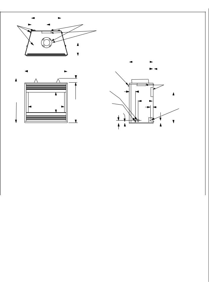
FIREPLACE SPECIFICATIONS
FRAMING |
|
|
|
G |
|
|
|
|
|
|
(Louvered Front Model Shown) |
||
SPACERS |
|
|
|
|
|
|
|
|
|
|
|||
|
|
|
|
|
|
|
|
|
|
|
|
||
(Top and Sides |
|
|
|
H |
|
|
|
|
|
|
|
|
* *See Note 1 |
|
|
|
|
|
|
|
|
|
|
||||
and Rear) |
|
|
|
|
|
|
|
|
|
|
|||
|
|
|
|
|
|
|
|
|
|
|
*CONCENTRIC FLUE |
||
|
|
|
|
|
|
|
|
|
|
|
|
|
|
|
|
|
|
|
|
|
|
|
|
|
|
|
FLUE - 4-1/2 (114) |
|
|
|
|
|
|
|
|
|
|
|
|
|
COMBUSTION AIR - 7-1/2 (190) |
|
|
|
|
|
|
|
|
|
|
|
|
|
* MPD models have a top and rear vent |
|
|
|
|
|
|
|
|
|
|
|
|
||
|
|
|
|
|
|
|
|
|
|
|
|
|
MPDR models have only a rear vent |
|
|
|
|
|
|
|
|
|
|
|
|
|
MPDT models have only a top vent |
|
|
|
|
|
|
|
|
|
|
|
|
|
|
|
|
|
|
|
|
|
|
|
|
J |
|
* *Note 1 - Collars protrude one inch on MPDT-3328 and MPDR-3328 models. |
|
|
|
|
|
|
|
|
|
|
|
|
|
|
|
|
|
|
|
|
|
|
|
|
|
|
|
|
|
|
|
|
|
|
|
|
|
|
|
|
|
|
|
|
|
|
|
|
|
|
|
|
|
Top View |
|
|
|
|
|
|
|
|
NOTE - Eyebrow |
|
|
|
|
|
|
|
|
|
|
|
|
|
|
N |
|
|
|
|
|
|
|
|
|
|
|
|
|
|
|
|
|
|
|
|
|
|
|
||||||||
|
|
|
|
|
|
|
|
|
|
|
|
|
|
|
|
|
|
|
|
|
|
|
|
|
|
|
|
|
|
|
|
|
|
|
|
|
|
|
|
|
|
|
|
|
|
|
|
|
|
|
|
|
|
|
|||||||||||
|
|
|
|
|
|
|
|
|
|
|
|
|
|
|
|
|
|
|
|
|
|
|
|
|
|
|
|
|
|
|
|
|
|
|
|
|
|
|
|
|
|
|
|
|
|
|
|
|
|
|
|
|
|
|
|
|
|
|
|
|
|||||
|
|
|
|
|
|
|
|
|
|
|
|
|
|
|
|
|
|
|
|
|
|
|
|
hood shown as positioned |
|
|
|
|
|
|
|
|
|
|
|
|
|
|
|
|
|
|
|
|
|
1/2 (13) |
|
|
|
|
|
|
|
||||||||||||
|
|
|
|
|
|
|
|
|
|
|
|
E |
|
|
|
|
|
3 (76) |
|
|
in louvered front model. |
|
|
|
|
|
|
|
|
|
|
|
|
|
|
|
|
|
|
|
|
|
|
|
|
|
|
|
|
||||||||||||||||
|
|
|
|
|
|
|
|
|
|
|
|
|
|
|
|
|
|
|
|
|
|
GAS INLET |
|
|
|
|
|
|
|
|
|
|
|
|
|
|
|
|
|
|
|
|
|
|
|
|
|
|
|
|
|
* * See Note 1 |
|
|
|
||||||||||
|
|
|
|
|
|
|
|
|
|
|
|
|
|
|
|
|
|
|
|
|
|
|
|
|
|
|
|
|
|
|
|
|
|
|
|
|
|
|
|
|
|
|
|
|
|
|
|
|
|
|
|
|
|
||||||||||||
|
|
|
|
|
|
|
|
|
|
|
|
|
|
|
|
|
|
|
|
|
|
|
|
|
|
|
|
|
|
|
|
|
|
|
|
|
|
|
|
|
|
|
|
|
|
|
|
|
|
|
|
||||||||||||||
|
|
|
|
|
|
|
|
|
|
|
|
|
|
|
|
|
|
|
|
|
|
|
|
|
|
|
|
|
|
|
|
|
|
|
|
|
|
|
|
|
|
|
|
|
|
|
|
|
|
|
|
|
|
|
|
||||||||||
|
|
|
|
|
|
|
|
|
|
|
|
|
|
|
|
|
|
|
|
|
|
|
|
|
|
|
|
|
|
|
|
|
|
|
|
|
|
|
|
|
|
|
|
|
|
|
|
|
|
|
|
|
|
|
|
||||||||||
|
|
|
|
|
|
|
|
|
|
|
|
|
|
|
|
|
|
|
|
|
|
|
|
|
|
|
|
|
|
|
|
|
|
|
|
|
|
|
|
|
|
|
|
|
|
|
|
|
|
|
|
|
|
|
|
||||||||||
|
|
|
|
|
|
|
|
|
|
|
|
|
|
|
|
|
|
|
|
|
|
|
|
|
|
|
|
|
|
|
|
|
|
|
|
|
|
|
|
|
|
|
|
|
|
|
|
|
|
|
|
|
|||||||||||||
|
|
|
|
|
|
|
|
|
|
|
|
|
|
|
|
|
|
|
|
|
|
|
|
|
|
|
|
|
|
|
|
|
|
|
|
|
|
|
|
|
|
|
|
|
|
|
|
|
|
|
|
|
|
|
|
|
|
|
|
|
|
|
|||
|
|
|
|
|
|
|
|
|
|
|
|
|
|
|
|
|
|
|
|
|
|
|
|
(Either Side |
6 (152) |
|
|
|
|
|
|
|
|
|
|
|
|
|
|
|
|
|
|
|
|
|
|
|
|
|
|
|
|
|
|
|
|
|
|
||||||
|
|
|
|
|
|
|
|
|
|
|
|
|
|
|
|
|
|
|
|
|
|
|
|
and bottom) |
|
|
|
|
|
|
|
|
|
|
|
|
|
|
|
|
|
|
|
|
|
|
|
|
|
|
|
|
|
|
|
|
|
|
|||||||
|
|
|
|
|
|
|
|
|
|
|
|
|
|
|
|
|
|
|
|
|
|
|
|
|
|
|
|
|
|
|
|
|
|
|
|
|
|
|
|
|
|
|
|
|
|
|
|
|
|
|
|
|
|
|
|
|
|||||||||
|
|
|
|
|
|
|
|
|
|
|
|
|
|
|
|
|
|
|
|
|
|
|
|
|
|
|
|
|
|
|
|
|
|
|
|
|
|
|
|
|
|
|
|
|
|
|
|
|
|
|
|
|
|
|
|
|
|
|
|
|
|
|
|||
|
|
|
A |
|
|
|
|
|
|
|
|
|
|
|
|
|
|
|
OPTIONAL ELECTRICAL |
|
|
|
|
|
|
|
|
|
|
|
|
|
|
|
|
|
|
|
|
|
|
|
|
|
|
|
|
|
|
|
|
|
|
ELECTRICAL |
|
|
|
||||||||
|
|
|
|
|
|
C |
|
|
|
|
B |
|
|
|
|
|
|
|
|
|
|
|
|
|
|
|
|
|
L |
|
|
|
|
|
|
|
|
|
|
|
|
|
|
|
|
|
|||||||||||||||||||
|
|
|
|
|
|
|
|
|
|
|
|
|
|
|
|
|
|
|
INLET KNOCKOUT, |
|
|
|
|
|
|
|
|
|
|
|
|
|
|
|
|
|
|
|
|
|
|
|
|
|
|
|
|
|
|
|
|||||||||||||||
|
|
|
|
|
|
|
|
|
|
|
D |
|
|
|
|
|
|
|
|
|
|
REQUIRING A FIELD |
|
|
|
|
|
|
|
|
|
|
|
|
|
|
|
|
|
|
|
|
|
|
|
|
|
|
1-5/8 |
|
F** |
INLET |
|
|
|
||||||||||
|
|
|
|
|
|
|
|
|
|
|
|
|
|
|
|
|
|
|
|
PROVIDED JUNCTION BOX |
|
|
|
|
|
|
|
|
|
|
|
|
|
|
|
|
|
|
|
|
|
|
|
|
|
|
(42) |
|
|
|
|
|
2-3/4 x 2 (70 x 51) |
||||||||||||
|
|
|
|
|
|
|
|
|
|
|
|
|
|
|
|
|
|
|
|
|
|
|
|
|
|
|
|
|
|
|
|
|
|
|
|
|
|
|
|
|
|
|
|
|
|
|
|
|
|
|
|||||||||||||||
|
|
|
|
|
|
|
|
|
|
|
|
|
|
|
|
|
|
|
|
|
|
|
|
|
|
|
|
|
|
|
|
|
|
|
|
|
|
|
|
|
|
|
|
|
|
|
|
|
|
|
|||||||||||||||
|
|
|
|
|
|
|
|
|
|
|
|
|
|
|
|
|
|
|
|
|
|
1-3/8 (35) |
|
|
|
|
|
|
|
|
|
|
|
|
|
|
|
|
|
|
|
|
|
|
|
|
|
COVER PLATE with |
|||||||||||||||||
|
|
|
|
|
|
|
|
|
|
|
|
|
|
|
|
|
|
|
|
|
|
|
|
|
(Either Side) |
|
|
|
|
|
|
|
|
|
|
|
|
|
|
|
|
|
|
|
|
|
|
|
M |
|
|
|
|||||||||||||
|
|
|
|
|
|
|
|
|
|
|
|
|
|
|
|
|
|
|
|
|
|
|
|
|
|
|
|
|
|
|
|
|
|
|
|
|
|
|
|
|
|
|
|
|
|
|
|
|
|
|
KNOCKOUT) |
|
|
|
|||||||||||
|
|
|
|
|
|
|
|
|
|
|
|
|
|
|
|
|
|
|
|
|
|
|
|
|
|
|
|
|
|
|
|
|
|
|
|
|
|
|
|
|
|
|
|
|
|
|
|
|
|
|
|
|
|||||||||||||
|
|
|
|
|
|
|
|
|
|
|
|
|
|
|
|
|
|
|
|
|
|
|
|
|
K |
|
|
|
|
|
|
|
|
|
|
|
|
|
|
|
|
|
|
|
|
|
|
|
|
|
|
|
|
|
|
|
|
|
|
|
|
|
|||
|
|
|
|
|
|
|
|
|
|
|
|
|
|
|
|
|
|
|
|
|
|
|
|
|
|
|
|
|
|
|
|
|
|
|
|
|
|
|
|
|
|
|
|
|
|
|
|
|
|
|
|
|
|
|
|
|
|
|
|
|
|
|
|
||
|
|
|
|
|
|
|
|
|
|
|
|
|
|
|
|
|
|
|
|
|
|
|
|
|
|
|
|
|
|
|
|
|
|
|
|
|
|
|
|
|
|
|
|
|
|
|
|
|
|
|
|
|
|
|
|
|
|
|
|
|
|
|
|||
|
|
|
|
|
|
|
|
|
|
|
|
|
|
|
|
|
|
|
|
|
|
|
|
|
|
|
|
|
|
|
|
|
|
|
|
|
|
|
|
|
|
|
|
|
|
|
|
|
|
|
|
|
|
|
|
|
|
|
|
|
|
|
|
||
|
|
|
|
|
|
|
|
|
|
|
|
|
|
|
|
|
|
|
|
|
|
|
|
|
|
|
|
|
|
|
|
|
|
|
|
|
|
|
|
|
|
|
|
|
|
|
|
|
|
|
|
|
|
|
|
|
|
|
|
||||||
|
|
|
|
|
|
|
|
|
|
Front View |
|
|
|
|
|
|
|
|
|
|
|
|
|
|
|
|
|
|
|
Right Side View |
|
|
|
|
|
**Rear vent models only |
|||||||||||||||||||||||||||||
|
|
|
|
|
|
|
|
|
|
|
|
|
|
|
|
|
|
|
|
|
|
|
|
|
|
|
|
|
|
|
|
|
|
||||||||||||||||||||||||||||||||
|
|
|
|
|
|
|
|
|
|
|
|
|
|
|
|
|
|
|
|
|
|
|
|
|
|
|
|
|
|
|
|
|
|
|
|
|
|
|
|||||||||||||||||||||||||||
|
Model No. |
|
|
|
|
A |
B |
|
C |
|
|
D |
|
E |
|
**F |
|
|
|
G |
|
|
|
H |
|
|
|
|
J |
|
K |
|
L |
M |
|
N |
|
|
|||||||||||||||||||||||||||
|
MPDT-3328 |
|
in. |
33 1/8 |
30 1/8 |
17 |
|
27 1/2 |
|
33 1/8 |
|
19 5/8 |
|
21 1/2 |
|
10 3/4 |
|
|
|
|
6 13/16 |
|
3 |
|
|
8 11/32 |
2 2/3 |
|
13 |
|
|
||||||||||||||||||||||||||||||||||
|
MPDR-3328 |
|
mm |
841 |
|
765 |
432 |
|
699 |
|
841 |
|
498 |
|
546 |
|
|
273 |
|
|
|
|
|
|
173 |
|
|
|
|
76 |
|
|
212 |
|
70 |
|
330 |
|
|
||||||||||||||||||||||||||
|
|
|
|
|
|
|
|
|
|
|
|
|
|
|
|
|
|
|
|
|
|
|
|
|
|
|
|
|
|
|
|
|
|
|
|||||||||||||||||||||||||||||||
|
MPD-3530 |
|
in. |
35 1/8 |
32 1/8 |
19 |
|
29 1/2 |
|
35 1/8 |
|
21 11/16 |
|
24 7/8 |
|
12 7/16 |
|
|
9 |
|
|
|
|
3 |
|
|
9 |
|
|
3 |
|
16 |
|
|
|||||||||||||||||||||||||||||||
|
|
|
|
|
|
|
|
|
|
|
|
|
|
|
|
|
|
|
|
|
|
|
|
|
|
|
|
|
|
|
|
|
|
|
|
|
|
|
|
|
|
|
|
|
|||||||||||||||||||||
|
|
|
|
|
|
|
|
mm |
892 |
|
816 |
483 |
|
749 |
|
892 |
|
551 |
|
632 |
|
|
316 |
|
|
|
|
|
|
220 |
|
|
|
|
76 |
|
|
220 |
|
76 |
|
406 |
|
|
|||||||||||||||||||||
|
MPD-4035 |
|
in. |
40 1/8 |
37 1/8 |
24 |
|
34 1/2 |
|
40 1/8 |
|
26 11/16 |
|
29 7/8 |
|
14 15/16 |
|
9 |
|
|
|
|
3 |
|
|
9 |
|
|
3 |
|
16 |
|
|
||||||||||||||||||||||||||||||||
|
|
|
|
|
|
|
|
|
|
|
|
|
|
|
|
|
|
|
|
|
|
|
|
|
|
|
|
|
|
|
|
|
|
|
|
|
|
|
|
|
|
|
|
|
|||||||||||||||||||||
|
|
|
|
|
|
|
|
mm |
1019 |
|
943 |
610 |
|
876 |
|
1019 |
|
678 |
|
759 |
|
|
379 |
|
|
|
|
|
|
220 |
|
|
|
|
76 |
|
|
220 |
|
76 |
|
406 |
|
|
|||||||||||||||||||||
|
MPD-4540 |
|
in. |
40 1/8 |
37 1/8 |
24 |
|
39 1/2 |
|
45 1/8 |
|
26 11/16 |
|
34 7/8 |
|
17 7/16 |
|
|
9 |
|
|
|
|
3 |
|
|
9 |
|
|
3 |
|
16 |
|
|
|||||||||||||||||||||||||||||||
|
|
|
|
|
|
|
|
|
|
|
|
|
|
|
|
|
|
|
|
|
|
|
|
|
|
|
|
|
|
|
|
|
|
|
|
|
|
|
|
|
|
|
|
|
|||||||||||||||||||||
|
|
|
|
|
|
|
|
mm |
1146 |
|
943 |
610 |
|
1003 |
|
1146 |
|
678 |
|
886 |
|
|
443 |
|
|
|
|
|
|
220 |
|
|
|
|
76 |
|
|
220 |
|
76 |
|
406 |
|
|
|||||||||||||||||||||
Figure 11 |
|
|
|
|
|
|
|
|
|
|
|
|
|
|
|
|
|
|
|
|
|
|
|
|
|
|
|
|
|
|
|
|
|
|
|
|
|
|
|
|
|
|
|
|
|
|
|
|
|
|
|
|
|
|
|
|
|
|
|||||||
|
|
|
|
|
|
|
|
|
|
|
|||||||||||||||||||||||||||||||||||||||||||||||||||||||
Step 3. INSTALL THE VENT SYSTEM |
|
|
|
These fireplaces are designed, tested and |
|
|
|
|
Massachusetts And New York City, NY |
||||||||||||||||||||||||||||||||||||||||||||||||||||||||
|
|
|
|
||||||||||||||||||||||||||||||||||||||||||||||||||||||||||||||
General Information |
|
|
|
|
|
|
|
|
|
listed for operation and installation with, |
|
|
|
|
Requirements |
|
|
|
|
|
|
|
|
||||||||||||||||||||||||||||||||||||||||||
|
|
|
|
|
|
|
|
|
and only with, Secure Vent™ Direct Vent |
|
|
|
|
These appliances are approved for installation |
|||||||||||||||||||||||||||||||||||||||||||||||||||
|
|
|
|
|
|
|
|
|
|
|
|
|
|
|
|
|
|
|
|
|
|
|
|||||||||||||||||||||||||||||||||||||||||||
|
|
|
|
|
|
|
|
|
|
|
|
|
|
|
|
|
|
|
System Components, Secure Flex™ Flex- |
|
|
|
|
||||||||||||||||||||||||||||||||||||||||||
These instructions should be used as a guide- |
|
|
|
|
|
in the following USA locations listed in the |
|||||||||||||||||||||||||||||||||||||||||||||||||||||||||||
|
ible Vent Components manufactured by |
|
|
|
|
||||||||||||||||||||||||||||||||||||||||||||||||||||||||||||
line and do not supersede local codes in any |
|
|
|
|
|
following: |
|
|
|
|
|
|
|
|
|
|
|
|
|
||||||||||||||||||||||||||||||||||||||||||||||
way. Install vent according to local codes, |
|
Security Chimneys International and Z- |
|
|
|
|
Massachusetts: |
|
|
|
|
|
|
|
|
||||||||||||||||||||||||||||||||||||||||||||||||||
these instructions, the current National Fuel |
|
FLEX™ Model GA Venting Systems listed |
|
|
|
|
|
|
|
|
|
|
|
|
|||||||||||||||||||||||||||||||||||||||||||||||||||
Gas Code (ANSI-Z223.1) in the USA or the |
|
to UL1777 and ULCS635 manufactured by |
|
|
|
|
These fireplaces are approved for installation |
||||||||||||||||||||||||||||||||||||||||||||||||||||||||||
|
|
|
|
|
in the US state of Massachusetts if the follow- |
||||||||||||||||||||||||||||||||||||||||||||||||||||||||||||
current standards of CAN/CGA-B149.1 and - |
|
Flexmaster Canada Limited. |
|
|
|
|
|
|
|
|
|
|
|||||||||||||||||||||||||||||||||||||||||||||||||||||
|
|
|
|
|
|
|
|
|
|
|
ing additional requirements are met- |
||||||||||||||||||||||||||||||||||||||||||||||||||||||
B149.2 in Canada. |
|
|
|
|
|
|
|
|
|
|
|
|
|
|
|
|
|
|
|
|
|
|
|
|
|
|
|
|
|
|
|
|
|
|
|
||||||||||||||||||||||||||||||
|
|
|
|
|
|
|
|
|
|
|
|
|
|
|
|
|
|
|
|
|
|
|
|
|
|
|
|
|
|
|
|
|
|
|
|
|
|
|
|
|
|
|
|
|
|
|
|
|
|
|
|
|
|
|
|
|
|
||||||||
|
|
|
|
|
|
|
|
|
|
|
|
|
|
|
|
|
|
|
These approved vent system components |
|
|
|
|
• Installation and repair must be done by a |
|||||||||||||||||||||||||||||||||||||||||
|
|
|
|
|
|
|
|
|
|
|
|
|
|
|
|
|
|
|
are labeled for identification. DO NOT use |
|
|
|
|
plumber or gas fitter licensed in the Common- |
|||||||||||||||||||||||||||||||||||||||||
|
|
|
|
|
|
|
|
|
|
|
|
|
|
|
|
|
|
|
anyothermanufacturer'sventcomponents |
|
|
|
|
wealth of Massachusetts. |
|
|
|
|
|
||||||||||||||||||||||||||||||||||||
|
|
|
|
|
|
|
|
|
|
|
|
|
|
|
|
|
|
|
with these appliances. These fireplaces |
|
|
|
|
• The flexible gas line connector used shall not |
|||||||||||||||||||||||||||||||||||||||||
|
|
|
|
|
|
|
|
|
|
|
|
|
|
|
|
|
|
|
|
|
|
|
exceed 36 inches (92 centimeters) in length. |
||||||||||||||||||||||||||||||||||||||||||
|
|
|
|
|
|
|
|
|
|
|
|
|
|
|
|
|
|
|
must be vented directly to the outside. |
|
|
|
|
||||||||||||||||||||||||||||||||||||||||||
|
|
|
|
|
|
|
|
|
|
|
|
|
|
|
|
|
|
|
|
|
|
|
• The individual manual shut-off must be a T- |
||||||||||||||||||||||||||||||||||||||||||
|
|
|
|
|
|
|
|
|
|
|
|
|
|
|
|
|
|
|
|
|
|
|
|
|
|
|
|
|
|
|
|
|
|
|
|
|
|
|
|
|
|
|
|||||||||||||||||||||||
|
|
|
|
|
|
|
|
|
|
|
|
|
|
|
|
|
|
|
|
|
|
|
|
|
|
|
|
|
|
|
|
|
|
|
|
|
|
|
|
|
|
|
handle type valve. |
|
|
|
|
|
|||||||||||||||||
|
|
|
|
|
|
|
|
|
|
|
|
|
|
|
|
|
|
|
|
|
NOTE: DIAGRAMS & ILLUSTRATIONS NOT TO SCALE. |
|
|
|
|
|
|
|
|
|
|
|
|
|
|
|
|
|
|
|
|
|
|
|
|
9 |
|||||||||||||||||||
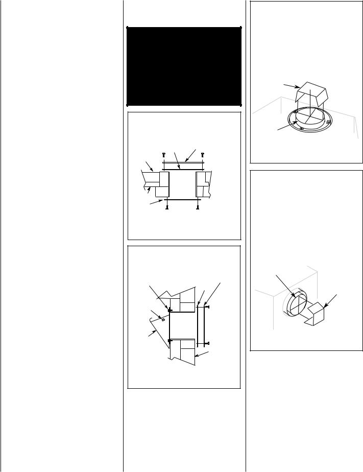
Massachusetts Horizontal Vent Requirements
In the Commonwealth of Massachusetts, horizontal terminations installed less than seven
(7) feet above the finished grade must comply with the following additional requirements:
•A hard wired carbon monoxide detector with an alarm and battery back-up must be installed on the floor level where the gas fireplace is installed. The carbon monoxide detector must comply with NFPA 720, be ANSI/UL 2034 listed and be ISA certified.
•A metal or plastic identification plate must be permanently mounted to the exterior of the building at a minimum height of eight (8) feet above grade and be directly in line with the horizontal termination. The sign must read, in print size no less than one-half (1/2) inch in size, GAS VENT DIRECTLY BELOW. KEEP CLEAR OF ALL OBSTRUCTIONS.
New York City, NY:
These fireplaces are approved for installation in New York City in the US state of New York.
The vent system may not service multiple appliances, and must never be connected to a flue serving a solid fuel burning appliance. The vent pipe is tested to be run inside an enclosing wall (such as a chase). There is no requirement for inspection openings in the enclosing wall at any of the joints in the vent pipe.
Preparing the Appliance Vent Collar on MPD-3530/4035/4540 Series (Combined Top and Rear Vent) Models
Each of the unit's two vent collars are sealed with a cover plate and a seal plate and gasket. The cover, and seal plate and gasket must be removed from the vent collar being used. Refer to Figure 12 for top vent usage and Figure 13 for rear, and the following steps to prepare the appropriate collar for use.
From the vent collar being used, remove the four screws securing the vent seal plate and gasket. Remove and discard the seal plate and gasket.
When the top vent collar is being used, from inside the firebox, loosen the two screws in the keyhole slots of the cover plate and remove the remaining two cover plate securing screws. Remove and discard the cover plate. Reinstall and securely tighten all four screws.
When the rear vent collar is being used, from inside the firebox, remove the two screws securing the lintel to the rear wall of the firebox, then remove the lintel. Remove the four cover plate securing screws. Remove and discard the cover plate.
10
Reinstall and securely tighten all four cover plate screws. Re-secure the lintel to the rear wall of the firebox.
WARNING: FAILURE TO REINSTALL AND SECURELY TIGHTEN COVER PLATE SCREWS COULD RESULT IN LEAKAGE OF FLUEPRODUCTSINTOTHELIVINGSPACE. VENTCOVERPLATEANDVENTSEALPLATE MUST REMAIN SECURELY INSTALLED ON UNUSED VENT COLLAR. FAILURE TO DO SO COULD RESULT IN LEAKAGE OF FLUE PRODUCTS INTO LIVING SPACE.
ON MPD-3530/4035/4540 SERIES MODELS (COMBINED TOP AND REAR VENT UNITS)
TOP VENT SEAL & COVER PLATE REMOVAL
WHEN USING THE TOP VENT
(OUTSIDE UNIT) |
VENT SEAL PLATE |
|
GASKET |
|
SECURING |
CABINET TOP |
SCREWS |
TOP VENT
FIREBOX TOP
VENT
COVER PLATE COVER PLATE SECURING SCREWS
(INSIDE UNIT)
CROSS SECTION
Figure 12
ON MPD-3530/4035/4540 SERIES MODELS (COMBINED TOP AND REAR VENT UNITS)
REAR VENT SEAL & COVER PLATE REMOVAL
WHEN USING THE REAR VENT
COVER PLATE |
VENT SEAL PLATE |
SECURING SCREWS |
GASKET |
|
|
LINTEL |
SECURING |
SECURING |
|
SCREWS |
SCREWS |
|
REAR VENT |
LINTEL |
|
|
CABINET BACK |
(INSIDE UNIT) |
(OUTSIDE UNIT) |
CROSS SECTION
Figure 13
Installation of Vent Restrictor
A vent restrictor may be needed with this appliance, install vent restrictor (provided) in the appliance top flue outlet as shown in Figure 14
(MPDT-3328, MPD-3530, MPD-4035 and MPD4540) or rear flue outlet as shown in Figure 15
(MPD-3530, MPD-4035 and MPD-4540). It is held in place by friction, only.
NOTE: DIAGRAMS & ILLUSTRATIONS NOT TO SCALE.
VENT RESTRICTOR INSTALLATION |
|
|
(TOP VENT) |
A vent restrictor may be needed when |
|
vertically terminating the vent system above |
|
the roof (when using the appliance top vent), |
|
install vent restrictor in the top vent of the |
|
fireplace outlet on MPD-3530/4035/4540 |
|
and MPDT-3328 series models. |
|
If needed, install the restrictor orientated as |
|
shown, either from inside or outside the unit, |
|
in the inner fireplace collar. |
|
RESTRICTOR |
|
INNER |
|
FIREPLACE |
|
COLLAR |
APPLIANCE TOP |
|
|
|
VENT OUTLET |
Figure 14 |
|
VENT RESTRICTOR INSTALLATION
(REAR VENT)
A vent restrictor may be needed when horzontally terminating the vent system from the rear of the appliance (when using the appliance rear vent), install vent restrictor in the rear vent of the fireplace outlet on MPD-3530/4035/4540 series models, in any installation that has a vertical vent run in excess of three feet (0.914 meters).
If needed, install the restrictor orientated as shown, either from inside or outside the unit, in the inner fireplace collar.
INNER FIREPLACE |
APPLIANCE REAR |
COLLAR |
VENT OUTLET |
|
RESTRICTOR |
Figure 15
Select Venting System - Horizontal or Vertical
With the appliance secured in framing, determine vent routing and identify the exterior termination location. The following sections describe vertical (roof) and horizontal (exterior wall) vent applications. Refer to the section relating to your installation. A list of approved venting components is shown in the two tables on page 27 and the two tables on page 28.
 Loading...