


LENNOX HEARTH PRODUCTS
 WARNINGS
• Hot! Do not touch! The glass and surfaces of this appliance will be hot during operation and will retain heat for a while after shutting off the appliance. Severe burns may result.
• Carefully supervise children in the same room as appliance.
•If small children are present in the home, it is recommended that this appliance be fitted with a screen door or screen panel kit. See Page 12 for ordering information.
OTL Report No. 116-F-02-05
WARNING:IFTHEINFORMATIONINTHISMANUAL IS NOT FOLLOWED EXACTLY, A FIRE OR EXPLOSION MAY RESULT CAUSING PROPERTY DAMAGE, PERSONAL INJURY OR LOSS OF LIFE.
FOR YOUR SAFETY: Do not store or use gasoline or other flammable vapors or liquids in the vicinity of this or any other appliance.
FOR YOUR SAFETY: What to do if you smell gas:
•DO NOT light any appliance.
•DO NOT touch any electrical switches.
•DO NOT use any phone in your building.
•Immediately call your gas supplier from a neighbor’s phone.
Follow your gas suppliers instructions.
•If your gas supplier cannot be reached, call the fire department.
Installation and service must be performed by a qualified installer, service agency or the gas supplier.
HOMEOWNER'S CARE AND OPERATION INSTRUCTIONS
DIRECT VENT
SPECTRA SERIES
VENTED GAS FIREPLACE HEATERS - DIRECT VENT MODELS P/N 875,020M REV. C 05/2006
MODELS
LSS-35CN LSS-40CN
LSS-35CP LSS-40CP
RETAIN THESE INSTRUCTIONS
FOR FUTURE REFERENCE
A French manual is available upon request. Order Form Number 875,020CF.
Ce manuel d’installation est disponible en francais, simplement en faire la demande. Numéro de la pièce 875,020CF.
AVERTISSEMENT: ASSUREZ-VOUS DE BIEN SUIVRE LESINSTRUCTIONSDONNÉDANSCETTENOTICEPOUR RÉDUIRE AU MINIMUM LE RISQUE D'INCENDIE OU POUR ÉVITER TOUT DOMMAGE MATÉRIEL, TOUTE BLESSURE OU LA MORT.
POUR VOTRE SÉCURITÉ: Ne pas entreposer ni utiliser d'essence ni d'autre vapeurs ou liquides inflammables dans le voisinage de cet appareil ou de tout autre appareil.
POUR VOTRE SÉCURITÉ: Que faire si vous sentez une odeur de gaz:
•Ne pas tenter d'allumer d'appareil.
•Ne touchez à aucun interrupteur. Ne pas vous servir des téléphones se trouvant dans le batiment où vous vous trouvez.
•Evacuez la piéce, le bâtiment ou la zone.
•Appelez immédiatement votre fournisseur de gaz depuis un voisin. Suivez les instructions du fournisseur.
•Si vous ne pouvez rejoindre le fournisseur de gaz, appelez le service dos incendies.
L'installation et service doit être exécuté par un qualifié
installeur, agence de service ou le fournisseur de gaz.
1

CONGRATULATIONS!
In selecting this LENNOX Signature Series Direct-Vent Gas Appliance you have chosen the finest and most dependable fireplace to be found anywhere. A beautiful, prestigious, alternative to a wood burning fireplace. Welcome to a Family of tens of thousands of satisfied LENNOX Fireplace Owners.
Please read and carefully follow all of the instructions found in this manual. Please pay special attention to the safety instructions provided in this manual. The Homeowner's Care and Operation Instructions included here will assure that you have many years of dependable and enjoyable service from your LENNOX product.
TABLE OF CONTENTS |
|
|
Introduction ..................................... |
page |
2 |
General Information ......................... |
page |
2 |
Operation/Care of Your Appliance .... |
page |
3 |
RF Comfort Control Valve Operation page |
3 |
|
Transmitter Operation ...................... |
page |
4 |
Trouble shooting ............................. |
page |
5 |
Glass Cleaning ................................. |
page |
6 |
Maintenance .................................... |
page |
6 |
Maintenance Schedule ..................... |
page |
7 |
Front Glass Enclosure Panel, |
|
|
Removal and Installation ............... |
page |
8 |
Burner Adjustments ......................... |
page |
8 |
Flame Appearance and Sooting ....... |
page |
8 |
Adjustment ...................................... |
page |
9 |
Vent Restrictor ................................ |
page |
9 |
Log Placement ................................. |
page |
10 |
Rockwool Placement ....................... |
page |
10 |
Pilot Inspection ............................... |
page |
10 |
Warranty .......................................... |
page |
11 |
Replacement Parts .......................... |
page |
11 |
Product Reference Information ....... |
page |
11 |
Accessory Components ................... |
page |
11 |
Replacement Parts List ..................... |
page |
14 |
INTRODUCTION
The Fireplace models covered in this manual are Direct-Vent sealed combustion vented gas fireplace heaters designed for residential application. Direct-Vent appliances operate with the combustion chamber completely isolated from the inside atmosphere. All air for combustion is brought in from the outside and exhaust gases are vented through the same direct vent, vent system.
These appliances feature a comfort control valve which allows remote control of temperature, fan and flame appearance. These appliances also use a spark ignitor (piezo) that allows the appliance's pilot gas to be lit without the use of matches. This system provides continued service in the event of a power outage.
The external electrical power (120v) is required to operate the provided circulating blower.
These appliances comply with National Safety Standards and are tested and listed by OmniTest Laboratories (Report No. 116-F-02-5) to ANSI Z21.88-2002 (in Canada, CSA-2.33-2002), and CAN/CGA-2.17-M91 in both USA and Canada, as vented gas fireplace heaters.
The Installation must conform to local codes or, in the absence of local codes, with the
National Fuel Gas Code, ANSI Z223.1/NFPA 54, or the Natural Gas and Propane Installation Code, CSA B149.1. The appliance, when installed, must be electrically grounded in accordance with local codes or, in the absence of local codes, with the National Electrical Code, ANSI/NFPA 70, or the Canadian Electrical Code, CSA C22.1.
DO NOT ATTEMPT TO ALTER OR MODIFY THE CONSTRUCTION OF THE APPLIANCE OR ITS COMPONENTS. ANY MODIFICATION OR ALTERATION MAY VOID THE WARRANTY, CERTIFICATION AND LISTINGS OF THIS UNIT.
WARNING: IMPROPER INSTALLATION, ADJUSTMENT, ALTERATION, SERVICE OR MAINTENANCE CAN CAUSE INJURY OR PROPERTY DAMAGE. REFER TO THIS MANUAL. FOR ASSISTANCE OR ADDITIONAL INFORMATION CONSULT A QUALIFIED INSTALLER, SERVICE AGENCY OR THE GAS SUPPLIER.
2 |
NOTE: DIAGRAMS & ILLUSTRATIONS NOT TO SCALE. |
|
|
GENERAL INFORMATION
Note: Installation and repair should be performed by a qualified service person. The appliance should be inspected annually by a qualified professional service technician. More frequent inspections and cleanings may be required due to excessive lint from carpeting, bedding material, etc. It is imperative that the control compartment, burners and circulating air passage ways of the appliance be kept clean.
S'assurer que le brùleur et le compartiment des commandes sont propres. Voir les instructions d'installation et d'utilisation qui accompagnent l'appareil.
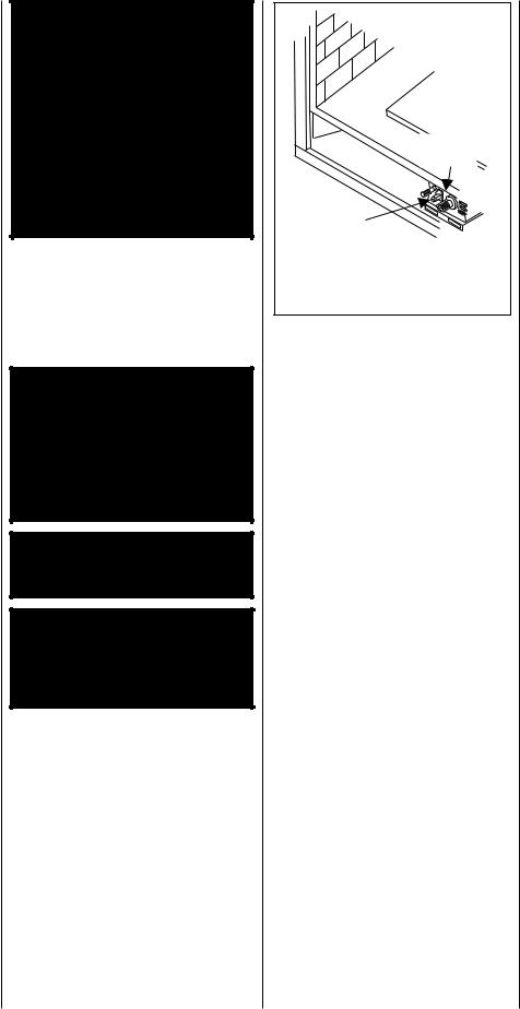
Provide adequate clearances around air openings and adequate accessibility clearance for service and proper operation. Never obstruct the front openings of the appliance.
Due to high temperatures the appliance should be located out of traffic and away from furniture and draperies. Locate furniture and window coverings accordingly.
WARNING: THESE FIREPLACES ARE VENTED HEATERS. DO NOT BURN WOOD OR OTHER MATERIAL IN THESE APPLIANCES.
These appliances are designed to operate on natural or propane gas only.
Input of millivolt models is variable. These rates are shown in the following table:
|
|
Maximum |
Minimum |
Model |
Fuel |
Input |
Input |
|
|
(BTU/H) |
(BTU/H) |
LSS-35CN |
Nat. Gas |
33,000 |
23,500 |
|
|
|
|
LSS-35CP |
LP Gas |
31,000 |
23,500 |
|
|
|
|
LSS-40CN |
Nat. Gas |
41,500 |
28,400 |
|
|
|
|
LSS-40CP |
LP Gas |
39,000 |
30,700 |
|
|
|
|
The following table shows the units' orifice size fortheelevationsof0-4500feet(0-1370meters).
Model |
Fuel |
Rear |
Front |
|
Burner |
Burner |
|||
|
|
|||
|
|
|
|
|
LSS-35CN |
Nat. Gas |
#44 |
#50 |
|
|
|
|
|
|
LSS-35CP |
LP Gas |
#55 |
#61 |
|
|
|
|
|
|
LSS-40CN |
Nat. Gas |
#42 |
#45 |
|
|
|
|
|
|
LSS-40CP |
LP Gas |
0.054" |
#56 |
|
|
|
|
|
Maximum manifold pressure is 3.5 in. w.c. (0.87 kPa) for natural gas and 10 in. w.c. (2.49 kPa) for LP/Propane gas.
Do not use these appliances if any part has been under water. Immediately call a qualified, professional service technician to inspect the appliance and to replace any parts of the control system and any gas control which have been under water.
Ne pas se servir de cet appareil s'il a été plongé dans l'eau, complètement ou en partie. Appeler un technicien qualifié pour inspecter l'appareil et remplacer toute partie du système de contrôle et toute commande qui ont été plongés dans l'leau.
Test gage connections are provided on the front of the millivolt gas control valve (identified OUT for the manifold side and IN for inlet pressure.
Minimum inlet gas pressure to these appliances is 5.0 inches water column (1.24 kPa) for natural gas and 11 inches water column (2.74 kPa) for propane for the purpose of input adjustment.
Maximum inlet gas supply pressure to these appliances is 10.5 inches water column (2.61 kPa) for natural gas and 13.0 inches water column (3.23 kPa) for propane.
The appliance must be isolated from the gas supply piping system (by closing its individual manual shut-off valve) during any pressure testing of the gas supply piping system at test pressures equal to or less than ¹⁄ psig (3.5 kPa).
The appliance and its individual shut-off valve must be disconnected from the gas supply piping system during any pressure testing of that system at pressures in excess of ¹⁄ psig (3.5 kPa).
These appliances must not be connected to a chimney or flue serving a separate solid fuel burning appliance.
Any safety guard or screen removed for servicing the appliance must be replaced prior to operating the appliance.
WARNING: FAILURE TO COMPLY WITH THE INSTALLATION AND OPERATING INSTRUCTIONS PROVIDED IN THIS DOCUMENT WILL RESULT IN AN IMPROPERLY INSTALLED AND OPERATING APPLIANCE, VOIDING ITS WARRANTY. ANY CHANGE TO THIS APPLIANCE AND/OR ITS OPERATING CONTROLS IS DANGEROUS. IMPROPER INSTALLATION OR USE OF THIS APPLIANCE CAN CAUSE SERIOUS INJURY OR DEATH FROM FIRE, BURNS, EXPLOSION OR CARBON MONOXIDE POISONING.
Carbon Monoxide Poisoning: Early signs of carbon monoxide poisoning are similar to the flu with headaches, dizziness and/or nausea. If you have these signs, obtain fresh air immediately. Turn off the gas supply to the appliance and have it serviced by a qualified professional, as it may not be operating correctly.
WARNING: CHILDREN AND ADULTS SHOULD BE ALERTED TO THE HAZARDS OFHIGHSURFACETEMPERATURES.USE CAUTION AROUND THE APPLIANCE TO AVOID BURNS OR CLOTHING IGNITION. YOUNG CHILDREN SHOULD BE CAREFULLY SUPERVISED WHEN THEY ARE IN THE SAME ROOM AS THE APPLIANCE.
WARNING: DO NOT PLACE CLOTHING OR OTHER FLAMMABLE MATERIALS ON OR NEAR THIS APPLIANCE.
AVERTISSEMENT: SURVEILLER LES ENFANTS. GARDER LES VÊTEMENTS, LES MEUBLES, L'ESSENCE OU AUTRES LIQUIDES À VAPEUR INFLAMMABLES LOIN DE L'APPAREIL.
OPERATION AND CARE OF YOUR APPLIANCE
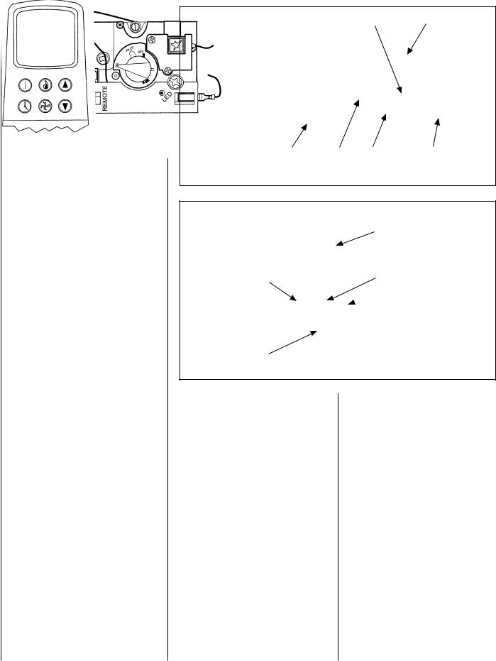
For piezo ignitor location, refer to Figure 1.
The control compartment is located behind the bottom front face piece. For access:
In the Cast Iron Face accessory - simply lift up and pull directly out.
In the Rectangular or Arched Face accessory - Pivot the main face door (bottom) on the two hinge pins, and drop down to open.
NOTE: DIAGRAMS & ILLUSTRATIONS NOT TO SCALE.
Honeywell |
Gas Valve |
Piezo |
Ignitor |
Honeywell RF Control Millivolt Gas Valve |
Showing Piezo Ignitor Location |
Figure 1 |
INSTRUCTIONS FOR RF COMFORT CONTROL VALVE
The Comfort Control Valve allows remote control of temperature, fan and flame appearance.
Note: The antenna should hang in free air and away from any grounded metal.
Operation (refer to Figure 2, page 4 )
Step 1. If the manual switch is in the remote position, switch it to LOCAL.
Step 2. Turn the Pilotstat knob counterclockwise from OFF to the PILOT position, push the knob down and hold it in position. The pilot valve will open and allow gas to flow to the pilot burner.
Step 3. Actuate the plunger on the piezo (several times if necessary) until the pilot burner is lit. When the pilot burner is lit, the LED on the control will come on after approximately 40 seconds. The receiver/valve is fully powered.
Step 4. Release the knob. The shaft will move forward. The pilot burner should now stay burning. If the pilot burner goes out, repeat Steps 2 and 3.
Step 5. Turn the knob counterclockwise to the ON position. If the manual switch is in the LOCAL position, the main burner will turn on immediately.
3
Step 6. ON the initial use of a transmitter, a recognition operation is required between the receiver/valveandtransmitter. Changetheswitch from LOCAL to REMOTE. Press the fan or flame button on the transmitter within 30 seconds. The LED will blink indicating the transmitter will now work with the receiver/valve. If the switch continues in the REMOTE position, the transmitter will now control the main valve, flame modulation level and fan control.
Step 7. If the manual switch is in the LOCAL position, the valve will be at the highest fixed pressure setting. The transmitter will control the fan only.
Shut Off Procedure
If the manual switch is in the REMOTE position, the transmitter can shut off the main burner and fan. However, the control is still on and a command from the transmitter can turn on the main burner or fan.
To shut off the system, turn the pilotstat knob clockwise to the OFF position. This action closes the main gas and safety valves. The transmitter now cannot turn on the main burner or fan.
TRANSMITTER OPERATION - (refer to Figure 3 )
Off Mode
In the OFF mode, the fireplace flame and fan are off, the display will show OFF and displays the room temperature. If the receiver is in REMOTE mode, the fireplace will shut off.
On (Manual) Mode
In the ON mode, the room temperature, flame and fan levels will be shown. MANUAL will appear next to both the flame and fan icons.
When the control is in the ON mode, the flame and fan levels, and the delay timer are changed with the up and down buttons. To change the flame level, press the flame button followed by an arrow key. To change the fan level, press the fan key followed by an arrow key. Pushing the arrow key once will change the level by one unit.
Delay Timer Mode
The shut off delay timer has a maximum of 2 (two) hours and a minimum of 0 (zero) minutes. To change the timer level, press the time key followed by an arrow key. Pushing the key once will change the timer by 10 (ten) minutes.
4
Screw Cap Of Pilot |
Piezo Ignitor |
Adjustment |
|
Local/Remote |
Pilotstat |
LED |
Antenna |
Switch |
Knob |
|
|
Figure 2
Mode
- Auto
- On
- Off
Countdown
Timer 
Fan
Figure 3
Display
-Room Temperature
-Set Temperature
-Flame Height Level
-Fan Speed Level
-Countdown Timer
-Low Battery
Flame
Up
 (Increases Flame
Height, Fan Speed Timer, or Set Point)
 Down
Down
(Decreases Flame,
Fan Speed Timer, or Set Point)
Auto Mode
In the AUTO mode, the room temperature, set temperature, flame and fan levels will be shown. AUTO will appear next to both the flame and fan icons.
When the control is in the AUTO mode, the main burner will turn on/off or modulate based on the heat needed to maintain the set temperature. The flame level will change automatically to optimize the heat output needed to maintain the set temperature. To change the set temperature, press the up or down key. Pushing a key once will change the temperature by 1 (one) degree. The setting temperature range from 40° F (4.5° C) to 90° F (32.0° C).
In the AUTO mode, the fan speed will increase with increasing flame height or decrease with decreasing flame height. "AUTO" is displayed next to the flame and fan icons.
Fan Override During Auto Mode
If a lower or higher fan speed is desired when operating in the AUTO mode, the fan speed can be overridden by pushing the fan button followed by the up or down key.
Pushing a key once will change the fan level by one unit. In this mode "AUTO" is displayed next to the flame icon and "MANUAL" is displayed next to the fan icon.
Change Between F/C Temperature Units
Push the up and down arrow keys simultaneously for at least 3 seconds to toggle between Fahrenheit and Celsius units.
Disable Thermostat Function
To disable the thermostat function in the AUTO mode, push the time and down key simultaneously for at least 3 seconds.
NOTE: DIAGRAMS & ILLUSTRATIONS NOT TO SCALE.

To Change Batteries
1.Remove cover on the backside of the transmitter. Install 3 AAA batteries as shown inside the cover and reattach the cover.
2.Once steps 1 thru 3 in OPERATION are completed, receiver/valve and transmitter are now ready. Press any button on transmitter for recognition precess to occur between the receiver/valve and transmitter.
3.Use functions as described in TRANSMITTER section.
Troubleshooting
Step 1. Locate LED light on valve.
Step 2. LED will blink after every valid command received by the transmitter; this is not an error.
Step 3. Failure codes may occur anytime after pilot burner is lit.
Step 4. Sequence is failure code followed by light not blinking for 4 seconds.
Step 5. In the event of multiple failure codes, next failure code follows previous failure code by approximately 3 seconds
If an Error Code 3 is observed while performing the testing, complete the following:
Step 1. Make sure the spade connectors are pushed all the way on. If the Error Code 3 is still showing, then go to the next step.
Step 2. Switch the front two thermopile leads with the back two. Be sure the lead is connected to the spade with the white dot next to it (see Figure 4 ). If the Error Code 3 is still showing, replace the thermopiles.
If an Error Code 8 is observed while performing the testing, complete the following:
Step 1. Confirm that the valve is not in REMOTE mode.
•If the valve is producing Error Code 8 and in REMOTE mode, the valve is defective and should be replaced.
•If the valve is in LOCAL mode and producing Error Code 8, then go to the next step.
Step 2. Slide the Remote/Local switch to REMOTE and reprogram valve recognition (refer to in Operation section). The Error Code will clear itself after approximately 1 1/2 minutes and return to normal operation.
LED Failure Code |
Service Action |
(Number Of Blinks) |
|
8 |
Replace valve |
7Confirm stepper motor connection exists
5Confirm fan connection exists and works
4Confirm gas type; jumper in place
3 |
Replace thermopiles |
2 |
Turn fan ON |
1 |
No action required |
NOTE: Some keys are not active. This is normal.
COMFORT VALVE WIRING DIAGRAM |
AUTO PATH DIAGRAM |
CAUTION: LABEL ALL WIRES PRIOR TO
BLOWER DISCONNECTION WHEN SERVICING CONTROLS.
WIRING ERRORS CAN CAUSE IMPROPER AND
DANGEROUS OPERATION. VERIFY PROPER
OPERATION AFTER SERVICING.
BLACK
F M BLACK
WHITE
GREEN
GREEN
F M
WHITE
FF
|
White |
|
Dots |
|
VALVE |
|
RED |
|
WHITE |
|
RED |
Figure 4 |
WHITE |
Figure 5 |
NOTE: DIAGRAMS & ILLUSTRATIONS NOT TO SCALE. |
5 |
 Loading...