


 Loading...
Leica TPS1200
User Manual
Version 4.0
English

Introduction |
TPS1200 |
2 |
|
|
|
|
|
Introduction |
|
|
|
|
|
|
|
Purchase |
Congratulations on the purchase of a TPS1200 series instrument. |
|
|
|
|
|
|
|
|
This manual contains important safety directions as well as instructions for setting |
|
|
|
up the product and operating it. Refer to "7 Safety Directions" for further information. |
|
|
|
Read carefully through the User Manual before you switch on the product. |
|
|
|
|
|
|
|
|
|
Product identification
The type and the serial number of your product are indicated on the type plate. Enter the type and serial number in your manual and always refer to this information when you need to contact your agency or Leica Geosystems authorized service workshop.
Type: _______________
Serial No.: |
_______________ |
|
|

Symbols |
The symbols used in this manual have the following meanings: |
||
|
Type |
Description |
|
|
|
Danger |
Indicates an imminently hazardous situation which, if not |
|
|
avoided, will result in death or serious injury. |
|
|
|
|
|
|
|
Warning |
Indicates a potentially hazardous situation or an unintended |
|
|
use which, if not avoided, could result in death or serious |
|
|
|
|
injury. |
|
|
|
|
|
|
Caution |
Indicates a potentially hazardous situation or an unintended |
|
|
use which, if not avoided, may result in minor or moderate |
|
|
|
|
injury and/or appreciable material, financial and environmental |
|
|
|
damage. |
|
|
|
|
|
) |
Important paragraphs which must be adhered to in practice as |
|
|
they enable the product to be used in a technically correct and |
||
|
|
|
efficient manner. |
|
|
|
|
|
|
|
|
Trademarks |
• Windows and Windows CE are a registered trademark of Microsoft Corporation |
||
•CompactFlash and CF are trademarks of SanDisk Corporation
•Bluetooth is a registered trademark of Bluetooth SIG, Inc
All other trademarks are the property of their respective owners.
Introduction |
TPS1200 |
3 |

Table of Contents |
|
|
|
TPS1200 |
4 |
|
|
|
|
|
|
Table of Contents |
|
|
|
||
|
|
|
|
|
|
In this manual |
Chapter |
|
|
Page |
|
|
|
|
|
||
|
1 |
How to Use this Manual |
8 |
||
|
|
|
|
||
|
2 |
Description of the System |
12 |
||
|
|
|
|
|
|
|
|
2.1 |
System Components |
12 |
|
|
|
2.2 |
System Concept |
19 |
|
|
|
|
2.2.1 |
Software Concept |
19 |
|
|
|
2.2.2 |
Data Storage and Data Conversion Concept |
21 |
|
|
|
2.2.3 |
Power Concept |
23 |
|
|
2.3 |
Container Contents |
24 |
|
|
|
2.4 |
Instrument Components |
28 |
|
|
3 |
User Interface |
|
32 |
|
|
|
|
|
|
|
|
|
3.1 |
Keyboard |
|
32 |
|
|
3.2 |
Screen |
|
36 |
|
|
3.3 |
Operating Principles |
38 |
|
|
|
3.4 |
Icons |
|
44 |
|
4 |
Operation |
|
50 |
|
|
|
|
|
|
|
|
|
4.1 |
Instrument Setup |
50 |
|

4.2 |
Autodetect Behaviour |
53 |
||
4.3 |
Instrument Setup as SmartStation |
55 |
||
|
|
4.3.1 |
SmartStation Setup |
55 |
|
|
4.3.2 |
LED Indicators on SmartAntenna |
59 |
|
|
4.3.3 |
Working with the Clip-On-Housings for Devices |
61 |
|
|
4.3.4 |
LED Indicators on Clip-On-Housings |
65 |
4.4 |
Instrument Setup for Remote Control |
70 |
||
|
|
4.4.1 |
Remote Control Setup |
70 |
|
|
4.4.2 |
LED Indicators on RadioHandle |
72 |
4.5 |
Battery |
|
74 |
|
|
|
4.5.1 |
Operating Principles |
74 |
|
|
4.5.2 |
Instrument Battery |
76 |
|
|
4.5.3 |
SmartAntenna Battery |
78 |
4.6 |
Working with the CompactFlash Card |
80 |
||
4.7 |
Accessing Survey Application Program |
83 |
||
4.8 |
Guidelines for Correct Results |
86 |
||
|
5 Check & Adjust |
90 |
||
|
|
|
|
|
5.1 |
Overview |
|
90 |
|
5.2 |
Preparation |
94 |
||
5.3 |
Combined Adjustment (l, t, i, c and ATR) |
96 |
||
5.4 |
Tilting Axis Adjustment (a) |
101 |
||
5.5 |
Adjustment of the Circular Level |
106 |
||
5.6 |
Adjustment of the Reflectorless EDM |
109 |
||
|
|
|
|
|
Table of Contents |
|
TPS1200 |
5 |
|

Table of Contents |
|
|
TPS1200 |
6 |
|
|
|
5.7 |
Adjustment of the Laser Plummet |
114 |
|
|
|
5.8 |
Service of the Tripod |
118 |
|
6 |
Care and Transport |
120 |
|||
|
|
|
|
|
|
|
|
6.1 |
Transport |
|
120 |
|
|
6.2 |
Storage |
|
122 |
|
|
6.3 |
Cleaning and Drying |
123 |
|
|
|
6.4 |
Maintenance |
124 |
|
7 |
Safety Directions |
126 |
|||
|
|
|
|
|
|
|
|
7.1 |
General Introduction |
126 |
|
|
|
7.2 |
Intended Use |
127 |
|
|
|
7.3 |
Limits of Use |
129 |
|
|
|
7.4 |
Responsibilities |
130 |
|
|
|
7.5 |
International Warranty, Software Licence Agreement |
131 |
|
|
|
7.6 |
Hazards of Use |
133 |
|
|
|
7.7 |
Laser Classification |
139 |
|
|
|
|
7.7.1 |
Integrated Distancer, Invisible Laser |
139 |
|
|
|
7.7.2 |
Integrated Distancer, Visible Laser |
142 |
|
|
|
7.7.3 |
Automatic Target Recognition ATR |
148 |
|
|
|
7.7.4 |
PowerSearch PS |
150 |
|
|
|
7.7.5 |
Electronic Guide Light EGL |
152 |
|
|
|
7.7.6 |
Laser Plummet |
154 |
|
|
7.8 |
Electromagnetic Compatibility EMC |
158 |
|
|
|
7.9 |
FCC Statement, Applicable in U.S. |
161 |
|

8 Technical Data |
|
168 |
|
|
|
|
|
8.1 |
Angle Measurement |
168 |
|
8.2 |
Distance Measurement - Infrared IR |
169 |
|
8.3 |
Distance Measurement - Reflectorless RL |
172 |
|
8.4 |
Distance Measurement - Long Range LO |
175 |
|
8.5 |
Automatic Target Recognition ATR |
177 |
|
8.6 |
PowerSearch PS |
179 |
|
8.7 |
SmartStation |
180 |
|
|
8.7.1 |
SmartStation Accuracy |
180 |
|
8.7.2 |
SmartStation Dimensions |
182 |
|
8.7.3 |
SmartAntenna Technical Data |
183 |
8.8 |
Conformity to National Regulations |
187 |
|
|
8.8.1 |
Communication side cover with Bluetooth |
187 |
|
8.8.2 |
GFU17, Siemens MC45 |
188 |
|
8.8.3 |
GFU24, Siemens MC75 |
190 |
8.8.4GFU19 (US), GFU25 (CAN) CDMA MultiTech MTMMC-C 192
|
8.8.5 |
RadioHandle |
194 |
|
8.8.6 |
SmartAntenna with Bluetooth |
196 |
8.9 |
General Technical Data of the Instrument |
198 |
|
8.10 |
Scale Correction |
205 |
|
8.11 |
Reduction Formulas |
211 |
|
Index |
|
|
216 |
|
|
|
|
Table of Contents |
TPS1200 |
7 |

How to Use this Manual |
TPS1200 |
8 |
1 How to Use this Manual
)It is recommended to set-up the instrument while reading through this manual.
Path |
Main Menu: Manage...\Data stands for this working sequence: |
|
From the Main Menu select Manage... and then select Data. |
|
|
Screen |
CONFIGURE General Menu describes the name of the screen. |
|
|
Page |
Screens can have more than one page. Units page describes a specific page of a |
|
screen. For example: ’...in CONFIGURE Units & Formats, Units page...’ |
Fields and options Fields displayed on the screen are described as <Coord System:> or <Coord System: Swiss>, if ’Swiss’ is the selected coordinate system.
Index |
The index is at the end of the manual. |
)Keys, fields and options on the screens which are considered as self-explanatory are not explained.
Validity of this |
This manual applies to all TPS1200 instruments. Differences between the various |
manual |
models are marked and described. |

Available documentation
General description
Name of documentation |
Description |
User Manual |
All instructions required in order to operate the instru- |
|
ment to a basic level are contained in this User |
|
Manual. Provides an overview of the instrument |
|
together with technical data and safety directions. |
|
|
Name of documentation |
Description |
System Field Manual |
Describes the general working of the instrument in |
|
standard use. Intended as a quick reference field |
|
guide. |
|
|
How to Use this Manual |
TPS1200 |
9 |
How to Use this Manual |
TPS1200 |
|
10 |
|||
|
|
|
|
|
|
|
|
Name of documentation |
Description |
|
|
||
|
Applications Field Manual |
Describes specific onboard application programs in |
||||
|
|
|
standard use. Intended as a quick reference field |
|||
|
|
|
guide. The RoadRunner application program is |
|||
|
|
|
described in a separate manual. |
|
||
|
|
|
|
|
|
|
|
Technical Reference |
Overall comprehensive guide to the instrument and |
||||
|
Manual |
|
program functions. Included are detailed descriptions |
|||
|
|
|
of special software/hardware settings and soft- |
|||
|
|
|
ware/hardware functions intended for technical |
|||
|
|
|
specialists. |
|
|
|
|
|
|
|
|
|
|
|
Available documentation depending on use case |
|
||||
|
|
|
|
|
|
|
|
Use case |
User Manual |
System Field |
Application |
Technical |
|
|
|
|
|
Manual |
Programs |
Reference |
|
|
|
|
|
Field Manual |
Manual |
|
|
for |
|
for |
for |
for |
|
TPS |
TPS1200 |
|
TPS1200 |
TPS1200 |
TPS1200 |
|
|
|
|
|
|
|
|
TPS RCS |
RX1200 |
|
TPS1200 |
TPS1200 |
TPS1200 |
|
|
|
|
|
|
|
|
Use case |
User Manual |
System Field |
Application |
Technical |
|
|
|
Manual |
Programs |
Reference |
|
|
|
|
Field Manual |
Manual |
|
|
for |
for |
for |
for |
|
GPS |
GPS1200 |
GPS1200 |
GPS1200 |
GPS1200 |
|
|
|
|
|
|
|
GPS |
RX1200 |
GPS1200 |
GPS1200 |
GPS1200 |
|
SmartRover |
|
|
|
|
|
|
|
|
|
|
|
|
|
|
|
|
Format of the |
The TPS1200 CD contains the entire TPS1200 documentation in electronic format. |
||||
documentation |
All manuals are also available in printed form except for the Technical Reference |
||||
|
Manuals. |
|
|
|
|
|
|
|
|
|
|
How to Use this Manual |
TPS1200 |
11 |
Description of the System |
TPS1200 |
12 |
2 Description of the System
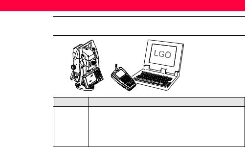
2.1System Components
Main components
|
RX1200 |
TPS12_198 |
TPS1200 |
Component |
Description |
TPS1200 |
• an instrument for measuring, calculating and capturing data. |
|
• comprised of various models with a range of accuracy classes. |
|
• integrated with an add-on GNSS system to form SmartStation. |
|
• combined with RX1200 to conduct remote control surveys. |
|
• connected with LGO to view, exchange and manage data. |

|
Component |
Description |
|
|
RX1200 |
A multi-purpose controller enabling the remote control of TPS1200. |
|
|
|
|
|
|
LGO |
An office software consisting of a suite of standard and extended |
|
|
|
programs for the viewing, exchange and management of data. |
|
|
|
|
|
|
|
|
|
Terminology |
The following terms and abbreviations may be found in this manual: |
||
|
|
|
|
|
Term |
|
Description |
|
TPS |
|
Total Station Positioning System |
|
|
|
|
|
GNSS |
|
Global Navigation Satellite System (generic term for satellite |
|
|
|
based navigation systems like GPS, GLONASS, SBAS) |
|
|
|
|
|
RCS |
|
Remote Control Surveying |
|
|
|
|
|
LGO |
|
LEICA Geo Office |
|
|
|
|
|
EDM |
|
Electronic Distance Measurement |
|
|
|
EDM refers to the laser distancer incorporated into the instru- |
|
|
|
ment which enables distance measurement. |
|
|
|
|
Description of the System |
TPS1200 |
13 |
Description of the System |
TPS1200 |
14 |
|
|
|
|
|
|
Term |
Description |
|
|
|
Three measuring modes are available: |
|
|
|
• infrared laser measurement mode IR. |
|
|
|
• visible red laser measurement mode RL. |
|
|
|
• long range visible red laser measurement mode LO. |
|
|
|
|
|
|
EDM |
This EDM refers to the infrared laser and the ability to measure |
|
|
Infrared IR |
distances to prisms. |
|
|
|
|
|
|
EDM |
This EDM refers to the visible red laser and the ability to measure |
|
|
Reflectorless RL |
distances without prisms. |
|
|
|
|
|
|
EDM |
This EDM refers to the visible red laser and the ability to measure |
|
|
Reflectorless LO |
extended distances to prisms. |
|
|
|
|
|
|
PinPoint |
PinPoint refers to the Reflectorless EDM technology which |
|
|
|
enables an increased measuring range with a smaller laser spot |
|
|
|
size. Two options are available: R100 and R300. |
|
|
|
|
|
|
EGL |
Electronic Guide Light |
|
|
|
An EGL fitted to an instrument assists with prism targeting. It |
|
|
|
consists of two differently coloured flashing lights located in the |
|
|
|
instrument telescope housing. The person holding the prism can |
|
|
|
align him/herself into the instrument’s line of sight. |
|
|
|
|
|

Term |
Description |
Motorised |
Instruments fitted with internal motors, enabling automatic hori- |
|
zontal and vertical turning are referred to as Motorised. |
ATR |
Automatic Target Recognition |
|
ATR refers to the instrument sensor which enables the automatic |
|
fine pointing to a prism. |
|
|
Automated |
Instruments fitted with ATR are referred to as Automated. |
|
Three automation modes are available with ATR: |
|
• None: no ATR - no automation and no tracking. |
|
• ATR: automatic fine pointing to a prism. |
|
• LOCK: automatic tracking of an already targeted prism. |
|
|
PowerSearch |
PowerSearch refers to the instrument sensor which enables the |
|
automatic rapid finding of a prism. |
|
|
SmartStation |
A TPS1200 instrument integrated with an add-on GNSS system, |
|
comprising hardware and software components, forms |
|
SmartStation. |
|
|
Description of the System |
TPS1200 |
15 |

Description of the System |
TPS1200 |
16 |
|
|
|
|
|
|
Term |
Description |
|
|
|
Components of SmartStation include SmartAntenna, |
|
|
|
SmartAntenna Adapter with attached clip-on-housing and |
|
|
|
antenna for a communication device and Communication side |
|
|
|
cover. |
|
|
|
SmartStation provides an additional instrument set-up method |
|
|
|
for determining instrument station coordinates. |
|
|
|
The GNSS principles and functionality of SmartStation derive |
|
|
|
from the principles and functionality of GPS1200 instruments. |
|
|
|
|
|
|
SmartAntenna |
SmartAntenna with integrated Bluetooth is a component of |
|
|
|
SmartStation. It can also be used independently on a pole, with |
|
|
|
a GNSS receiver and remote controller. |
|
|
|
|
|
|
RadioHandle |
A component of RCS is RadioHandle. It is both an integrated |
|
|
|
radio modem with attached antenna and instrument carry |
|
|
|
handle. |
|
|
|
|
|
|
Communication |
Communication side cover with integrated Bluetooth is a compo- |
|
|
side cover |
nent of SmartStation. In combination with RadioHandle it is also |
|
|
|
a component of RCS. |
|
|
|
|
|
|
|
|
|

Instrument models |
|
|
|
Model |
Description |
||
|
|||
|
TC1200 |
Basis electronic tachymeter. |
|
|
|
|
|
|
TCR1200 |
Additional components: Reflectorless EDM. |
|
|
|
|
|
|
TCRM1200 |
Additional components: Reflectorless EDM, Motorised. |
|
|
|
|
|
|
TCA1200 |
Additional components: Automated, Motorised. |
|
|
|
|
|
|
TCP1200 |
Additional components: Automated, Motorised, PowerSearch. |
|
|
|
|
|
|
TCRA1200 |
Additional components: Reflectorless EDM, Automated, Motorised. |
|
|
|
|
|
|
TCRP1200 |
Additional components: Reflectorless EDM, Automated, Motorised, |
|
|
|
PowerSearch. |
|
|
|
|
|
LEICA Geo Office |
• LGO supports GPS1200 and TPS1200 instruments. It also supports all other |
||
|
Leica TPS instruments. |
||
• LGO is based on a graphical user interface with standard Windows® operating procedures.
• LGO provides the following functionality:
Description of the System |
TPS1200 |
17 |

Description of the System |
TPS1200 |
18 |
|
|
|
|
|
|
Functionality |
Description |
|
|
Standard |
Includes data exchange between computer and instrument, data |
|
|
Functionality |
management including viewing and editing, reporting, creation |
|
|
|
and management of codelists, creation and use of format files for |
|
|
|
data conversion, uploading and deleting of system software and |
|
|
|
application programs. |
|
|
|
|
|
|
Extended |
Includes Coordinate transformations, GPS and GLONASS post |
|
|
Functionality |
processing, Level data processing, Network adjustment, GIS |
|
|
|
and CAD Export. |
|
|
|
|
|
•Supported operating systems: Windows® XP, Windows® 2000, Windows® ME.
•Refer to the online help of LGO for additional information.

2.2System Concept
2.2.1Software Concept
Description Software type
TPS1200 instruments use the same software concept.
Software type |
Description |
System |
This software comprises the central functions of the instrument. |
software |
It is also referred to as firmware. |
|
The programs Survey and Setup are integrated into the firmware |
|
and cannot be deleted. |
|
The English language is integrated into the firmware and cannot |
|
be deleted. |
|
|
Language |
Numerous languages are available for the TPS1200 instru- |
software |
ments. This software is also referred to as system language. |
|
The system software enables a maximum of three languages |
|
which can be stored at any one time - the English language and |
|
two other languages. The English language is the default |
|
language and cannot be deleted. One language is chosen as the |
|
active language. |
|
|
Description of the System |
TPS1200 |
19 |

Description of the System |
TPS1200 |
20 |
|
|
|
|
|
|
Software type |
Description |
|
|
Application |
A suite of optional survey-specific application programs are |
|
|
programs |
available for the instrument. |
|
|
|
Some of the programs are activated freely and require no licence |
|
|
|
key and others require purchasing and are only activated with a |
|
|
|
licence key. |
|
|
|
|
|
|
Customised |
Customised software specific to user requirements can be devel- |
|
|
application |
oped using the GeoC++ development kit. Information on the |
|
|
programs |
GeoC++ development environment is available on request from |
|
|
|
a Leica Geosystems representative. |
|
|
|
|
|
|
|
|
|
Software upload All instrument software is stored in the System RAM of the instrument. The software can be uploaded onto the instrument using the following methods:
•Using LGO the software is transferred via the serial interface to the CompactFlash card in the instrument, which is then stored to the System RAM.
•By connecting the CompactFlash card directly to the computer either via an internal card slot housing or an external OMNI drive, the software is transferred to the card, which is then stored to the System RAM.
2.2.2Data Storage and Data Conversion Concept
Description |
Data is stored within a job in a database on a memory device. This is either a |
||
|
CompactFlash card or an internal memory if fitted. |
||
|
|
|
|
Memory device |
CompactFlash card: |
A CompactFlash card housing is standard. A Compact- |
|
|
|
Flash card can be inserted and removed. Various storing |
|
|
|
capacities are available. |
|
|
|
) |
Whilst other CompactFlash cards may be used, |
|
|
Leica recommends Leica CompactFlash cards |
|
|
|
|
and cannot be held responsible for data loss or |
|
|
|
any other error that may occur when using a |
|
|
|
non-Leica card. |
|
Internal memory: |
An internal memory is optional. It resides inside the instru- |
|
|
|
ment. Available capacity: 64 MB. |
|
)Unplugging connecting cables or removing the CompactFlash card during the measurement may cause loss of data. Always return to TPS1200 Main Menu before removing the CompactFlash card and switch off the instrument before removing cables.
Description of the System |
TPS1200 |
21 |

Description of the System |
TPS1200 |
22 |
|
Data conversion |
Export |
|
|
|
Data can be exported from a job in a wide range of ASCII formats. The export format |
||
|
is defined in Format Manager which is a PC tool in LEICA Geo Office. Refer to the |
||
|
online help of LGO for information on creating format files. |
|
|
|
Import |
|
|
|
Data can be imported from ASCII, GSI8 or GSI16 format. |
|
|
|
|
||
Transfer raw data |
Raw data can be transferred between the database on the CompactFlash card or |
||
to LGO |
the internal memory of the instrument and LGO in two ways: |
|
|
•From the CompactFlash card or the internal memory directly via a serial interface to a project in LGO on a PC.
•From the CompactFlash card using for example an OMNI drive as supplied by Leica Geosystems to a project in LGO on a PC.
)CompactFlash cards can be used directly in an OMNI drive as supported by Leica Geosystems. Other PC card drives may require an adapter.

2.2.3Power Concept
General |
Use the Leica Geosystems batteries, chargers and accessories or accessories |
|
|
recommended by Leica Geosystems to ensure the correct functionality of the instru- |
|
|
ment. |
|
|
|
|
Power options |
Instrument |
|
|
Power for the instrument can be supplied either internally or externally. An external |
|
|
battery is connected to the instrument using a LEMO cable. |
|
|
Internal battery: |
One GEB221 battery fitted into the battery compartment. |
|
External battery: |
One GEB171 battery connected via cable, or |
|
|
One GEB70 battery connected via cable. |
|
SmartAntenna |
|
|
Power for the antenna is supplied internally. |
|
|
Internal battery: |
One GEB211 battery fitted into the antenna. |
|
|
|
Description of the System |
TPS1200 |
23 |
Description of the System |
TPS1200 |
24 |
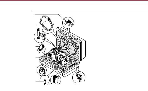
2.3Container Contents
Container for instrument and delivered accessories part 1 of 2
a |
|
|
|
|
b |
|
|
|
|
c |
|
|
a) |
Tribrach bracket for height meter |
|
|
|
||
|
|
|
b) |
Data transfer cable GEV102 |
|
|
|
c) |
Diagonal eyepiece GFZ3 or zenith |
d |
|
|
|
eyepiece GOK6 (eyepiece for steep |
|
|
|
sighting) - optional |
|
|
|
|
d) |
Counterweight for diagonal eyepiece or |
e |
|
|
|
zenith eyepiece - optional |
|
|
e) |
Instrument with supplied stylus and |
|
|
|
|
||
|
|
|
|
tribrach (with standard carry handle or |
|
|
|
|
RadioHandle attached) |
|
|
|
f) |
Protective cover for instrument and |
f |
|
|
|
sunshade for objective lens |
g |
|
|
g) |
Tip for mini prism |
h |
|
h) |
Internal battery GEB221 |
|
TPS12_010a |
i |
i) |
Mini prism and holder |
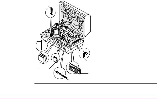
Container for instrument and a
delivered accessories
part 2 of 2
b
c 

d
TPS12_010b
a)Pocket knife - optional
b)Spare stylus
c)User manual
d) 2 x CompactFlash cards and covers e) Tool set for circular level and EDM
eadjustments - comprising two adjusting pins, one allen key and one screwdriver
f) |
Battery charger |
f g) |
Car adapter power plug for battery |
g |
charger (stored under battery charger) |
Description of the System |
TPS1200 |
25 |
Description of the System |
TPS1200 |
26 |
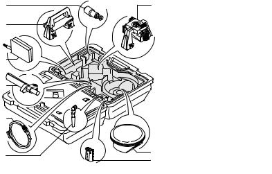
Container for SmartStation/RCS components
part 1 of 2
a
b
c
d
e
f
RX12_012
ga) 360° mini prism with adapter GRZ101
|
b) |
RadioHandle |
|
c) |
Radio modem with antenna |
|
|
TCPS27 |
|
d) |
Grip with circular bubble and |
|
|
fixing element GHT25 |
|
|
(without clamp) |
|
e) |
Y-cable GEV186 / battery |
|
|
cable GEV52 (stored over |
|
|
grip) |
|
f) |
Antenna for communication |
|
|
device in clip-on-housing |
|
g) |
SmartAntenna Adapter with |
|
|
communication device in |
h |
|
clip-on-housing |
h) |
SmartAntenna |
|
i |
i) |
Internal battery GEB211 |

Container for |
|
SmartStation/RCS |
a |
components |
b |
part 2 of 2 |
|
c 
d
RX12_004
e
a) 360° prism GRZ4
b)User manual
c)Tripod adapter for radio
modem GHT43 d) Spare stylus
e) External battery - GEB70 or GEB171
ff) 2 x internal batteries GEB211
g)RX1220 controller
gwith stylus and antenna
h)Pole holder GHT39
h(with clamp) (stored under RX1220 controller)
Description of the System |
TPS1200 |
27 |
Description of the System |
TPS1200 |
28 |
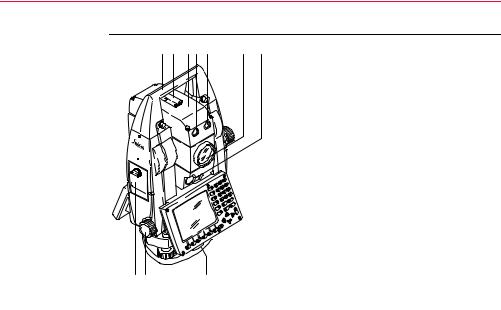
2.4Instrument Components
Instrument |
a b c d e |
components |
|
part 1 of 2 |
|
h i |
j |
TPS12_001a
f g
a)Carry handle
b)Optical sight
c)Telescope, integrating EDM, ATR, EGL, PS
d)EGL flashing diode - yellow
e)EGL flashing diode - red
f)Coaxial optics for angle and distance measurement, and exit port of visible laser beam for reflectorless instruments
g)PowerSearch
h)CompactFlash card compartment
i)Horizontal drive
j)Tribrach securing screw
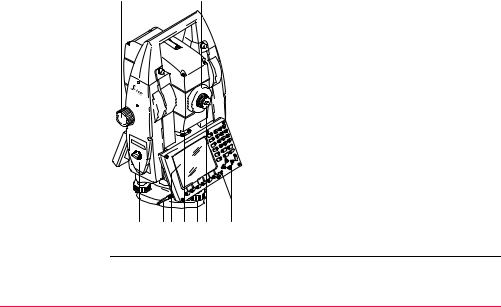
Instrument |
k |
l |
components |
|
|
part 2 of 2 |
|
|
|
|
k) |
Vertical drive |
|
|
l) |
Focusing ring |
|
|
m) |
Battery compartment |
|
|
n) |
Stylus for touch screen |
|
|
o) |
Screen |
|
|
p) |
Circular level |
|
|
q) |
Tribrach footscrew |
m n o p q r |
s |
r) |
Interchangeable eyepiece |
TPS12_001b |
|
s) |
Keyboard |
Description of the System |
TPS1200 |
29 |

Description of the System |
TPS1200 |
30 |
Instrument components for
SmartStation
a
b c d
e
TPS12_197
a)SmartAntenna
b)Antenna for communication device
c)Clip-on-housing for communication device
d)SmartAntenna Adapter
e)Communication side cover
Loading...