


 Loading...
Leica M165 FC
Leica M205 FA
User Manual
General Instructions
Safety concept
Before using your microscope for the first time, please read the "Safety concept" brochure included with your instrument. It contains additional information about handling and care.
Use in clean rooms
The Leica M series can be used in clean rooms without any problems.
Cleaning
ρρ Do not use any unsuitable cleaning agents, chemicals or techniques for cleaning.
ρρ Never use chemicals to clean colored surfaces or accessories with rubberized parts. This could damage the surfaces, and specimens could be contaminated by abraded particles.
ρρ In most cases, we can provide special solutions on request. Some products can be modified, and we can offer other accessories for use in clean rooms.
Servicing
ρρ Repairs may only be carried out by Leica Microsystems-trained service technicians. Only original Leica Microsystems spare parts may be used.
Responsibilities of person in charge of instrument
ρρ Ensure that the Leica stereomicroscope is operated, maintained and repaired by authorized and trained personnel only.
Leica M-series |
User Manual |
2 |
|
|
|

Important Safety Notes
User Manual
The individual modules of the Leica M stereomicroscopy series include an interactive CD-ROM with all relevant user manuals in 20 other languages. Keep it in a safe place, and readily accessible to the user. User manuals and updates are also available for you to download and print from our web site at www.stereomicroscopy.com.
This User Manual describes the special functions of the individual modules of the Leica M stereomicroscopy series and contains important instructions for their operational safety, maintenance, and accessories.
The "Safety concept" booklet contains additional safety information regarding the service work, requirements and the handling of the stereomicroscope, accessories and electrical accessories as well as general safety instructions.
You can combine individual system articles with articles from external suppliers (e.g. cold light sources, etc.). Please read the user manual and the safety requirements of the supplier.
Before installing, operating or using the instruments, read the user manuals listed above. In particular, please observe all safety instructions.
To maintain the unit in its original condition and to ensure safe operation, the user must follow the instructions and warnings contained in these user manuals.
Special manuals
Special manuals are provided for a number of accessories:
ρρ User Manual M2-216-1 for lamp housing with high-pressure mercury burner.
ρρ User Manual for ebq 100 isolated supply unit for 100W high-pressure mercury burners .
ρρ User Manual M2-267-1 for the motorized focus system.
ρρ User Manual M2-166-2 for FluoCombi III™.
Leica M-series |
User Manual |
3 |
|
|
|

Symbols Used
Warning of a danger
•This symbol indicates especially important information that must be read and
complied with.
Failure to comply can cause the following:
ρρ |
Hazards to personnel |
ρρ |
Functional disturbances or damaged instru- |
|
ments |
Warning of hazardous electrical voltage
This symbol indicates especially important information that is mandatory to
read and observe.
Failure to comply can cause the following:
ρρ |
Hazards to personnel |
ρρ |
Functional disturbances or damaged instru- |
|
ments |
Danger due to hot surface
This symbol warns against touching accessible hot surfaces, e.g. those of
light bulbs.
Important information
This symbol indicates additional information or explanations that intend to
provide clarity.
Explanatory notes
ρρ This symbol within the text stands for additional information and explanations.
Figures
(1)Numbers in parentheses within the descriptions relate to the figures and the items within those figures.
Leica M-series |
User Manual |
4 |
|
|
|

Safety Instructions
Description
The individual modules fulfill the highest requirements for observation and documentation of Leica stereomicroscopes of the M series.
Intended use
Refer to "Safety Concept" booklet
Non-intended use
Refer to "Safety Concept" booklet
Never use M series microscopes or their components for surgical procedures (e.g. on the eye) unless they are specifically intended for that purpose.
The instruments and accessories described in this operating manual have been tested for safety and potential hazards. The responsible Leica affiliate must be consulted whenever the instrument is altered, modified or used in conjunction with non-Leica components that
are outside of the scope of this manual.
Unauthorized alterations to the instrument or noncompliant use shall void all rights to any warranty claims.
Place of use
Refer to "Safety Concept" booklet
ρρ Electrical components must be placed at least 10 cm away from the wall and from flammable substances.
ρρ Avoid large temperature fluctuations, direct sunlight and vibrations. These conditions can distort measurements and micrographic images.
ρρ In warm and warm-damp climatic zones, the individual components require special care in order to prevent the build-up of fungus.
Responsibilities of person in charge of instrument
Refer to "Safety Concept" booklet
Ensure that:
ρρ The M series stereomicroscopes and accessories are operated, maintained and repaired by authorized and trained personnel only.
ρρ All operators have read, understood and observe this User Manual, and particularly the safety instructions.
Leica M-series |
User Manual |
5 |
|
|
|

Safety Instructions (cont'd.)
Repairs, service work
Refer to "Safety Concept" booklet
ρρ Only original Leica Microsystems spare parts may be used.
ρρ Before opening the instruments, switch off the power and unplug the power cable.
Touching the live circuit can cause injury.
Transport
ρρ Use the original packaging for shipping or transporting the individual modules of the Leica M stereomicroscopy series and the accessory components.
ρρ In order to prevent damage from vibrations, disassemble all moving parts that (according to the user manual) can be assembled and disassembled by the customer and pack them separately.
Integration in third-party products
Refer to "Safety Concept" booklet
Disposal
Refer to "Safety Concept" booklet
Legal requirements
Refer to "Safety Concept" booklet
EC Declaration of Conformity
ρρ Refer to "Safety Concept" booklet
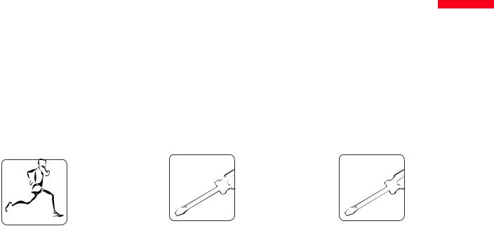
Health risks
•Workplaces with stereomicroscopes facilitate and improve the viewing task,
but they also impose high demands on the eyes and holding muscles of the user. Depending on the duration of uninterrupted work, asthenopia and musculoskeletal problems may occur. For
this reason, appropriate measures for reduction of the workload must be taken:
ρρ |
Optimal arrangement of workplace, work |
|
assignments and work flow (changing tasks |
|
frequently). |
ρρ |
Thorough training of the personnel, giving |
|
consideration to ergonomic and organiza- |
|
tional aspects. |
ρρ |
The ergonomic design and construction |
|
of the Leica M stereomicroscopy series are |
|
intended to reduce the exertion of the user |
|
to a minimum. |
Leica M-series |
User Manual |
6 |
|
|
|

Safety Instructions (cont'd.)
•Direct contact with eyepieces is a potential transmission method for bacterial
and viral infections of the eye.
The risk can be kept to a minimum by using personal eyepieces for each individual or detachable eyecups.
Light sources: Safety regulations
Protective measures of the manufacturer:
ρρ UV protection screen in front of the specimen plane prevents the user from looking directly into the UV rays.
ρρ |
Dummy filter carriers in the free positions |
|
of the rapid filter changer prevent direct UV |
|
radiation from reaching the eyes. |
ρρ |
UV filters are installed in the observation |
|
beam paths to protect the eyes. |
ρρ |
The stray-light protection on the lamp |
|
housing prevents irradiation of the hands. |
Warning
•UV radiation could damage the eyes. Therefore:
ρρ |
Never look into the light spot on the speci- |
|
men plane without a UV protection screen. |
ρρ |
Never look into the eyepieces if no excita- |
|
tion filter is in the beam path. |
ρρ |
Fill empty filter positions with dummy filter |
|
carriers (e.g. M165 FC). |
ρρ |
Do not select a white, strongly reflective |
|
background for the specimen. |
Leica M-series |
User Manual |
7 |
|
|
|

Safety Instructions (cont'd.)
Supply unit
Always unplug the supply unit from the power supply:
ρρ When installing and disassembling the lamp housing
ρρ |
Before opening the lamp housing |
ρρ |
When replacing the high-pressure mercury |
|
lamp and other parts, such as the heat- |
|
absorbing filter or the collector |
ρρ |
During maintenance work on the supply |
|
unit |
Lamp housing
•Never open the lamp housing while the lamp is switched on. Risk of explosion,
UV exposure, blinding!
•Before opening the lamp housing, allow it to cool off for at least 15 minutes.
Danger of explosion!
•Never cover the air duct on the lamp housing. Danger of fire!
Mercury lamp
ρρ Follow the user manual and safety instructions provided by the lamp manufacturer, and, in particular, the section on how to proceed if a lamp breaks and releases mercury.
ρρ |
For transport, remove the mercury lamp, |
|
transport it in its original packaging and |
|
protect moving parts in the lamp housing |
|
using the transport anchors. |
ρρ |
When it has reached the end of its rated life |
|
(follow the manufacturer's specifications |
|
and the minute meter on the supply unit). |
ρρ |
To minimize the risk of explosion, replace a |
|
discolored mercury lamp promptly. |
ρρ |
Leica Microsystems assumes no liability |
|
for damage caused by exploding, incor- |
|
rectly installed or improperly used mercury |
|
lamps. |
Leica M-series |
User Manual |
8 |
|
|
|

Contents
General Instructions |
2 |
Important Safety Notes |
3 |
Symbols Used |
4 |
Safety Instructions |
5 |
|
|
The Leica M Series for Fluorescence |
|
Congratulations! |
13 |
A Step Towards Infinity |
14 |
The Electronics: Comfort, Convenience and Safety |
15 |
The Modular Design: Everything is Relative |
16 |
Maximum Compatibility |
17 |
On We Go |
18 |
|
|
Assembly |
|
Assembling the Focusing Column for MDG Bases |
20 |
Assembling the Focusing Column with an Incident-light Base |
21 |
Motorized Focus: Restricting the Travel Path |
22 |
Optics Carrier |
23 |
Tube |
24 |
Eyepieces |
25 |
Objective |
26 |
UV Protection Screen – Assembly |
27 |
Objective Nosepiece – Assembly |
28 |
Objective Nosepiece – Adjusting Parfocality |
29 |
Transmitted-light Base TL ST |
30 |
FluoCombi III™ – Preparations |
31 |
FluoCombi III™ – Assembly |
32 |
FluoCombi III™ – Adjusting the Parfocality |
34 |
FluoCombi III™ – Centering the Objectives |
36 |
FluoCombi III™ – Filter and UV Protection Screen |
37 |
Transmitted-light Base TL BFDF: Before First Use |
38 |
Transmitted-light Base TL BFDF |
39 |
TL RC™ / TL RCI™ |
40 |
IsoPro™ Manual Mechanical Stage: Assembly |
41 |
Leica IsoPro™ Motorized Mechanical Stage: Assembly |
44 |
Cables: Connections |
48 |
Cables: Cable Duct |
49 |
Cables: Diagram |
50 |
Leica LED5000 MCI™ |
51 |
Leica LED5000 MCI™: Alternative Assembly |
52 |
Leica LED5000 RL |
53 |
Leica EL6000 – Safety Notes |
54 |
Leica EL6000 – Preparations |
57 |
Leica EL6000 – Connection to the Fluorescence Lamp Housing |
59 |
Leica EL6000 – Replacing the Lamp |
61 |
Leica EL6000 – Connection to the Fluorescence Lamp Housing (cont'd.)62
Leica M-series |
User Manual |
9 |
|
|
|
Quick Start Guide |
|
The Fastest Route to Success |
64 |
Overview of an M Series Microscope |
65 |
The Correct Interpupillary Distance |
66 |
Using the Eyepieces |
67 |
Focusing |
68 |
Adjusting the Resistance of the Focus Drive |
69 |
Changing Magnification (Zoom) |
70 |
Ratchet Steps and Magnification Levels |
71 |
Parfocality: More Comfort and Convenience for Your Work |
72 |
Iris Diaphragm |
73 |
|
|
Eyepieces |
|
Magnification Factors of the Eyepieces |
75 |
Health Notes |
76 |
Dioptric Correction |
77 |
Dioptric Correction and Parfocality |
78 |
Graticules |
79 |
|
|
Photography & Video |
|
Photography & Video |
81 |
Photo Tubes and C-mounts |
82 |
Trinocular Video/Phototube 50% |
83 |
Trinocular Video/Phototube 100% |
84 |
|
|
|
|
Microscope Carrier |
|
The Objective Nosepiece |
86 |
|
|
Objectives andOptical Accessories |
|
The Different Types of Objectives |
88 |
|
|
Bases |
|
Leica TL ST Transmitted-light Base: Controls |
90 |
Leica TL ST Transmitted-light Base: Operation |
91 |
Leica TL ST Transmitted-light Base: Changing Bulbs |
92 |
Leica TL BFDF Transmitted-light Base: Controls |
93 |
Leica TL BFDF Transmitted-light Base: Operation |
94 |
Leica TL RC™ / TL RCI™: Controls |
95 |
Leica TL RCI™: The Deflection Mirror |
96 |
Leica TL RCI™: Color Intensity and Temperature |
97 |
Leica TL RC™ / TL RCI™: Operation |
98 |
Leica TL RCI™: Methods in Transmitted Light |
99 |
Leica TL RCI™: Relief Images |
100 |
Using Filters |
102 |
Leica IsoPro™ (Non-motorized): Controls |
103 |
Leica IsoPro™ (Motorized): Controls |
104 |
Leica M-series |
User Manual |
10 |
|
|
|
System Illumination |
|
Leica LED5000 MCI™ |
106 |
Leica LED5000 RL |
108 |
Leica EL6000 – About the Instrument |
109 |
Leica EL 6000 – Operation |
111 |
Leica EL 6000 – Troubleshooting |
112 |
Cleaning and Maintenance |
113 |
|
|
Fluorescence |
|
Filter Changer |
115 |
FIM – Fluorescence Intensity Manager |
116 |
About Fluorescence Microscopy |
117 |
Rapid Filter Changers and Filter Types |
118 |
Simple filter holders |
119 |
Equipping the Filter Changer |
120 |
Observation without Fluorescence |
121 |
Double Iris Aperture |
122 |
Commissioning the Fluorescence System |
123 |
|
|
Accessories |
|
Leica SmartMove |
125 |
Leica SmartTouch™ |
126 |
Leica PSC Controller |
127 |
|
|
|
|
|
|
Dimensional Drawings |
|
|
Leica M165 FC |
129 |
|
Leica M205 FA |
132 |
|
Leica LED5000 MCI |
135 |
|
Leica LED5000 RL |
136 |
|
MATS TL |
137 |
|
|
|
|
Specifications |
|
|
Leica M165 FC / Leica M205 FA |
139 |
|
Leica EL6000 – Specifications |
143 |
|
Leica TL ST Transmitted-light Base |
145 |
|
Leica TL BFDF Transmitted-light Base |
146 |
|
Leica TL RC™ / TL RCI™ |
147 |
|
Leica IsoPro™ Motorized XY Stage |
148 |
|
|
|
|
Appendix |
|
|
Calculating the Total Magnification and Field of View Diameter |
150 |
|
Care, Maintenance, Contact Persons |
151 |
|
Leica M-series |
User Manual |
11 |
|
|
|
The Leica M Series for Fluorescence
Leica M-series |
User Manual |
12 |
|
|
|

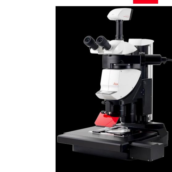
Congratulations!
Congratulations on obtaining your new Leica M series stereomicroscope. We are convinced it will exceed your expectations, as never before have we applied our decades of experience in the areas of optics, mechanical engineering and ergonomics in such an uncompromising manner.
The Leica M series embodies all the qualities you associate with the name Leica Microsystems: excellent objectives, high-quality engineering, and reliability. Furthermore, the modular design ensures that the M series adapts perfectly to your needs—no matter which accessories you require for your tasks.
The entire imaging system, including the zoom, objective and ErgoTube®, is apochromatically corrected with much technological effort. Contrast, sharpness, richness in detail, resolution, image and color fidelity are optimum. In addition, the patented illumination beam path guarantees at every zoomlevelthatlightutilizationisatamaximumandthatfluorescenceimages are intensely luminous on a jet black background.
Though the reliability and robustness of Leica stereomicroscopes is legendary, like any high-tech product, the Leica M series requires a certain degree of care and attention. Therefore, we recommend that you read this manual. It contains all the information you need regarding operation, safety and maintenance. Simply observing a few guidelines will ensure that even after years of intensive use, your stereomicroscope will continue to work as smoothly and reliably as on the very first day.
We wish you the best of success in your work—after all, you are now equipped with the best tool!
Leica M-series |
User Manual |
13 |
|
|
|

A Step Towards Infinity
Ever since their introduction by Horatio S. Greenough, stereomicroscopes have worked according to the optical principles based primarily on Ernst Abbe's research. For over a century, ingenious optics designers and engineers have worked to push magnification, resolution and image fidelity to the limit permitted by optics.
In doing so, they have always been constrained by the interrelation between three factors: the higher a microscope's resolution, the lower the available working distance. If one increases the distance of the optical axes, the three-dimen- sional image seen by the observer becomes distorted—a sphere becomes an ellipse, a flat surface curves towards the observer.
Limits are made to be broken
The Leica M205 FA is the world's first fluorescence stereomicroscope with a zoom range of 20.5:1. This accomplishment, however, was not enough for Leica's engineers. With the new FusionOptic™ in the Leica M205 FA, they have succeeded in going yet another step beyond previous limits. In addition to the increase in magnification, the resolution, too, has been increased to up to 1050 lp / mm, which corresponds to a resolved structure size of 472 nm.
Of course, this increase in performance benefits your everyday work. Set up your specimens on the microscope table with comfortable freedom of movement and discover details in stereomicroscopy that you could never see before.
* Leica M205 FA with 1.0× planapochromat and 10× eyepieces
Leica M-series |
User Manual |
14 |
|
|
|
The Electronics: Comfort, Convenience and Safety for Your Experiments
Never before have electronics been used as extensively in a Leica series as in the new M series lineup. Optics carrier, stand, base and illuminator are all connected using electrical contacts—which provides a number of advantages.
Reliability for your experiments
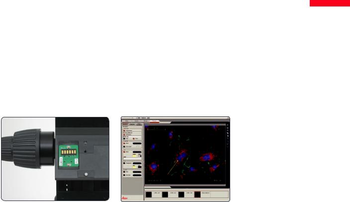
Exact reproducibility of results is an increasingly common demand, particularly in research and development. The continuous encoding captures parameters such as the magnification, the illumination, the position of the iris
diaphragm and more and transmits the information to the Leica LAS software. Thus you always know the conditions under which an image was acquired.
Fewer cables
A large part of the cables have been routed in the interior of the column. Data are also transferred via the interface between the column, the optics carrier and the carrier. The direct result is that you need fewer cables—this not only makes your workstation neater and more comfortable, it even makes it appear larger.
Contacts not only transmit data, but also supply the power.
Leica Application Suite (LAS) evaluates the transmitted data and can restore the test situation later.
Leica M-series |
User Manual |
15 |
|
|
|

The Modular Design: Everything is Relative
The Leica M series provides maximum flexibility in choosing equipment, thanks primarily to the modular configuration and the compatibility that Leica has painstakingly maintained for decades. The optics carriers, eyepieces, bases and more can be combined in any way you choose, allowing you to create the microscope that best suits your needs.
Despite this, you will notice that the controls and individual components do not differ significantly. Whichever configuration you choose, you will quickly feel right at home.
Have a special request? Let us know!
Leica Microsystems enjoys an exceptional reputation when it comes to devising customerspecific solutions. If you have a special request that cannot be met with standard parts, contact your Leica consultant. We have a solution for every problem.
Leica M-series |
User Manual |
16 |
|
|
|

Maximum Compatibility
Leica engineers were careful to ensure that the new Leica M series—like its predecessors— remains compatible with existing series. This means that objectives, bases, tubes and so on can be reused.
Objectives
All new objectives of the Leica M series are parfocal, meaning that when used with the objective nosepiece, they can be replaced while keeping the specimen in perfect focus.
If you prefer, you can continue to use the previous Leica objective series. In this case, parfocality is no longer guaranteed.
Tubes
The interface between the optics carrier and the tube has remained the same, so existing tubes fit the new M series. The new tubes are designed for eyepieces with field number 23, while the predecessor models were only designed for field number 21, resulting in a smaller object field.
Eyepieces
However, the new M-series eyepieces have an audible and tangible click to provide immediate feedback in case of accidental adjustment.
Leica M-series |
User Manual |
17 |
|
|
|
On We Go
If your new Leica microscope has already been assembled and commissioned by your Leica consultant, click here to skip through the installation instructions and go directly to the Quick Start Guide on Page 63.
If, on the other hand, you are assembling the microscope yourself, continue with the "Assembly" chapter, which begins on Page 19.
For everything you need to know about the correct use of fluorescence-related parts, refer to Page 114.
Leica M-series |
User Manual |
18 |
|
|
|
Assembly
Leica M-series |
User Manual |
19 |
|
|
|
Assembling the Focusing Column for MDG Bases
The first step is to connect the focusing column |
Assembling the column adapter |
Assembling the focusing column |
of the M series to the corresponding base. |
1. Securely install the column adapter on the |
2. Securely screw the focusing column to the |
|
column using the four included screws. |
base using the six included screws. |
Tools used |
|
|
ρρ Hex socket screwdriver, 3 mm |
|
|
Leica M-series |
User Manual |
20 |
|
|
|
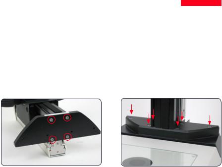
Assembling the Focusing Column with an Incident-light Base
When using an incident-light base, the focus- |
Assembly |
3. Screw the base securely onto the focusing |
ing column and motorized focus are installed |
1. Place the focusing column on the side. |
drive. |
directly on the base; no extension plate is |
|
|
required. |
|
|
Tools used |
|
|
ρρ Hex socket screwdriver, 3 mm |
|
|
2.Insert the four screws provided into the outer holes of the base.
Leica M-series |
User Manual |
21 |
|
|
|
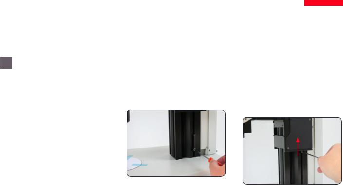
Motorized Focus: Restricting the Travel Path
 Depending on the work situation, it is
  useful to restrict the maximum travel path of the stereomicroscope. This prevents
injury during handling of the sample caused by fingers or hands becoming trapped or the specimen touching the objective or even being damaged by it.
Readjusting the motorized focus
The motorized focus is factory-adjusted and normally does not need to be readjusted— even if the maximum travel path is changed.
•Exception: If the power fails while the motorized focus is moving, the position
data are lost. In this case, the calibration must be repeated using the Leica LAS software or the Leica SmartTouch™. To do so, please consult the respective manual.
Restricting the bottom travel range
1.Move the motorized focus into the lowest position you want to reach.
2.Unscrew the screw of the limit stop on the side of the focusing column.
3.Push the limit stop to the height of the motorized focus.
It is easiest to move the limit stop by keeping the screwdriver inserted and moving it upwards.
4. Tighten the screw of the limit stop.
Leica M-series |
User Manual |
22 |
|
|
|
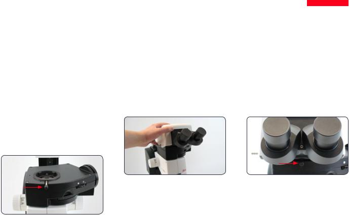
Optics Carrier
Tools used |
Assembling the optics carrier |
ρρ Hex socket screwdriver, 4 mm |
1. Place the optics carrier on the focusing |
|
column so that the screw fits into the thread |
|
provided and the lug fits into the groove. |
2.Press the optics carrier backwards to the focusing column and screw it in place using your other hand.
Leica M-series |
User Manual |
23 |
|
|
|
Tube
All intermediate tubes that fit between the optics carrier and the binocular tube are fitted in the same manner.
Tools used
ρρ No tools required.
Preparations
1.Unscrew the positioning screw and remove the protective cover.
Assembling the tube
2.Push the tube (for example, the inclined binocular tube) into the dovetail ring and rotate it slightly in both directions until the positioning screw meshes with the guide groove.
3.While holding the tube only slightly, carefully tighten the positioning screw. It is automatically brought to the correct position.
Leica M-series |
User Manual |
24 |
|
|
|
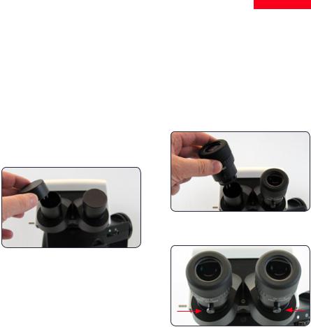
Eyepieces
Tools used |
Preparation |
Inserting the eyepieces |
|
ρρ No tools required. |
1. |
If you want to use an optional graticule, |
3. Push the eyepieces into the tubes as far as |
|
|
insert it now (Page 79). |
they will go and check to ensure that they |
Magnification range |
|
|
fit tightly and accurately. |
You can extend the overall magnification range |
2. |
Remove the plastic tube guard. |
|
using available 10×, 16×, 25× and 40× wide- |
|
|
|
field eyepieces for persons wearing glasses. |
|
|
|
4. Securely tighten the clamping screws.
Leica M-series |
User Manual |
25 |
|
|
|
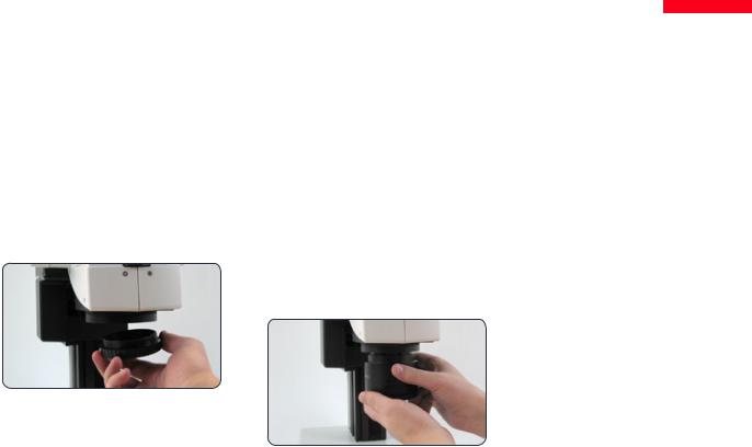
Objective
Tools used
ρρ No tools required.
Preparation
1.Remove the protective cap on the optics carrier by turning it.
Attaching the objective
•Hold the objective firmly during assembly and disassembly so that it does not
fall onto the stage plate. This applies particularly to the 2x planapochromatic objective, which is very heavy. Remove all specimens from the stage plate first.
2.Screw the objective clockwise into the optics carrier.
Alternative fastening options
ρρ If using the objective nosepiece, read the instructions on Page 28.
ρρ If using the Leica FluoCombi III™, read the instructions on Page 31.
Leica M-series |
User Manual |
26 |
|
|
|

UV Protection Screen: Assembly
Tools used
ρρ Allen key
Intended use
The UV protection screen in front of the specimen plane prevents the user from looking directly into the UV rays.
Safety Notes
•UV radiation can damage the eyes. Therefore, it is mandatory to install the
UV filter and adjust it correctly.
•Always position the UV protection screen so that the operator can never
look directly at the light spot.
Use with one objective
1.Adjust the UV protection screen laterally using the arm.
2.Unscrew the hexagon-head screw.
3.Adjust the UV protection screen using the arm.
4.Tighten the hexagon-head screw.
5.Fasten the UV protection screen using a hexagon-head screw to the left or right side of the microscope carrier.
Leica M-series |
User Manual |
27 |
|
|
|
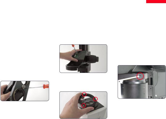
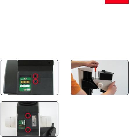
Objective Nosepiece – Assembly
Preparations
•Hold the objectives firmly during assembly and disassembly so that they
do not fall onto the stage plate.
ρρ Move the drive housing all the way upwards and remove the optics carrier, if the carrier has already been installed.
Assembly
1.Remove the transport anchor from the objective nosepiece.
2.Rotate the moving part by 90° and attach the objective nosepiece to the drive housing from the front (!). Screw the objective nosepiece firmly into place.
3.Unscrew the three Phillips screws on the objective mount of the optics carrier and remove the intermediate ring.
4.Screw the optics carrier onto the objective nosepiece.
5.Screw both objectives onto the objective nosepiece. It makes no difference which position an objective occupies.
6.Unscrew the locking screws on both sides of the objective nosepiece.
You can now adjust the parfocality (see instructions on the next page).
Leica M-series |
User Manual |
28 |
|
|
|

Objective Nosepiece – Adjusting Parfocality
The following procedure only has to be carried out once. Afterwards, both objectives are parfocal, meaning that the specimen remains in focus when the objective nosepiece is rotated.
This procedure must be repeated if you replace either of the two objectives with another.
The following example assumes the combination of the 1× and 2× planapochromats. If you are using another objective combination, replace the 2× objective in the description with the objective with the stronger magnification.
Preparation
ρρ |
Open the iris diaphragm. |
ρρ |
Set the dioptric correction of the eyepieces |
|
to "0". |
Adjustment
1.Rotate the 2× objective into the beam path and set it to the lowest magnification.
2.Focus on the specimen.
3.Rotate the 1× objective into the beam path.
4.Turn the objective on the thread in both directions until the specimen appears sharp.
5.Toggle to the 2× objective.
6.Select the strongest magnification and refocus until the specimen appears absolutely sharp.
7.Toggle to the 1× objective.
8.Turn the objective on the thread in both directions until the specimen appears absolutely sharp.
By means of zooming, check that the behavior of the objective is parfocal. Repeat the check with the other objective. If it is not parfocal, repeat the procedure.
9. Tighten the locking screws.
Leica M-series |
User Manual |
29 |
|
|
|
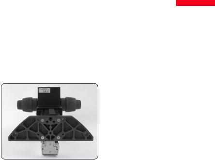
Transmitted-light Base TL ST
Unpacking the base |
Focusing drive and column |
2. |
Attach your focusing drive column from |
The base is delivered with the adapter plate |
1. Unscrew the extension plate from the base |
|
below using the four hexagon-head |
installed. Make sure the instruments are |
using the Allen key provided. |
|
screws. |
unpacked on a flat, sufficiently dimensioned, |
|
|
|
and non-slip surface. |
|
3. |
Re-attach the adapter plate to its origi- |
|
|
|
nal position using the six hexagon-head |
|
|
|
screws. |
Leica M-series |
User Manual |
30 |
|
|
|
Loading...