


M501
Leica M501
User manual
10 711 785 – Version D

Leica M501 / Ref. 10 711 785 / Version D

Chapter Overview
1
Leica M501 / Ref. 10 711 785 / Version D
Introduction 3
Controls 7
Preparation for Operation 9
Use 19
Safety Notes 22
Care and Maintenance 32
Messages and Warnings 36
Technical data 37

Table of Contents
2
Leica M501 / Ref. 10 711 785 / Version D
Page
Introduction
Design and function 4
Ceiling mounts 5
Controls
Control unit/lamp housing 6
Tilt head/focusing unit 6
Footswitch 6
Handswitch 7
Stand 7
Remote control for Leica Telescope Mount 7
Optics carrier 8
Binocular tube, eyepiece, tubes for second observer 8
Preparation for Operation
Retrofit the surgical microscope and balance
the swinging arm 9
Attach the binocular tube, eyepiece and objective 10
Set the interpupillary distance and eyepoint 12
Adjust for parfocality 12
Attach the adapter for accessories 13
Adjusting second-observer tube 14
Display/change the footswitch type 15
Switch the plus/minus movement directions
of the XY-unit 15
Disable/enable the function of the XY-Reverse button 15
Transport the surgical microscope 16
Position the surgical microscope at the OP stage 17
Sterile components 18
Setting the rest position on the Leica
Telescope Mount 18
Setting the rest position on the Leica Mini Mount 19
Use
Operating the surgical microscope 19
Positioning the microscope 20
Adjusting the focus 20
Adjusting the magnification 20
Adjusting the illumination 21
Setting the illumination type and the working distance
21
Safety Notes
Intended use 22
Directions for the operator of the instrument 22
Directions for the user of the instrument 22
Table 201 according to EN 60601-1-2:2001 23
Table 202 according to EN 60601-1-2:2001 24
Table 204 according to EN 60601-1-2:2001 25
Table 206 according to EN 60601-1-2:2001 26
Hazards associated with instrument use 27
Signs and labels 28
Page
Care and Maintenance
Changing the fuse 32
Changing the bulb 33
Inspecting the functioning 33
Notes on reprocessing of resterilizable products 34
Messages and Warnings
Ventilation 36
General malfunctions 36
Technical data
Electrical data 37
Microscope 37
Stands 38
Swing arm 39
Ambient conditions 39
Limitations of use 39
Standards 39
Dimensions 40
Introduction
3
Leica M501 / Ref. 10 711 785 / Version D
User manual
This user manual contains important safety
precautions as well as information on using the
instrument (see the chapter "Safety notes").
Before attempting to set up the product, carefully
read through the user manual.
Product identification
The model code and serial number of your product are provided
on the nameplate found on the underside of the control unit.
Write this data into your User Manual and always refer to it
when you contact us or the service workshop regarding any
questions you may have.
Model: Serial No.:
Symbols used in this manual
The symbols used in this user manual
have the following meanings:
Warning regarding use hazard or
Warning noncompliant use that can lead to
serious injury or death.
Warning regarding use hazard or non-
Caution compliant use that can lead to minor
injury, but significant article, property
or environmental damage.
Useful information that can help the user
operate the product correctly and effi-
ciently.
Request for action; here, you are
requested to take action.
➩
Introduction
4
Leica M501 / Ref. 10 711 785 / Version D
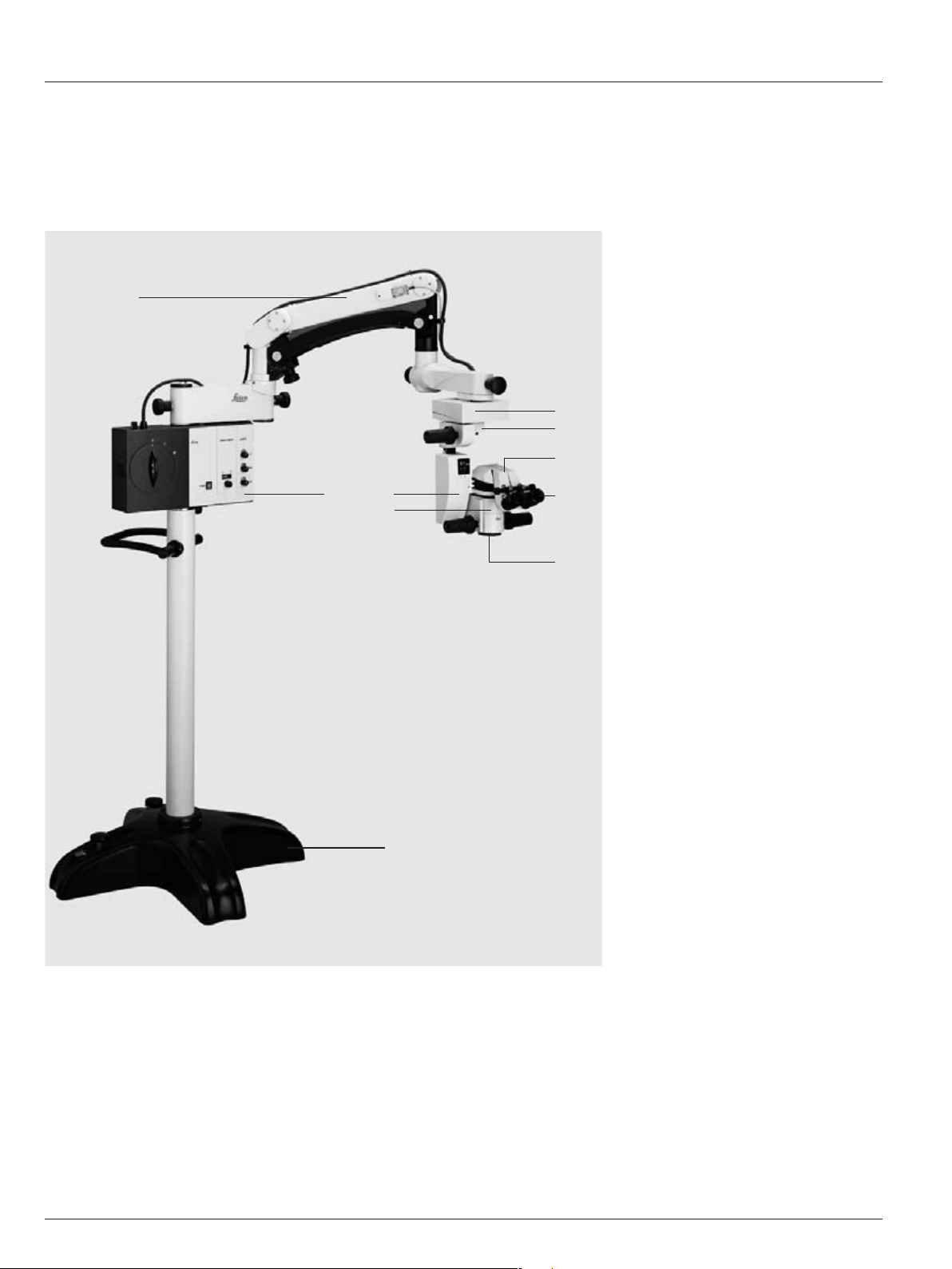
Design and function
1 Base
2 Control unit/lamp housing
3 Swing arm
4 XY-coupling (optional)
5 Tilt head
6 Focusing unit
7 Optics carrier
8 Binocular tube
9 Eyepieces
10 Objective
Floor stand
1
3
2
4
5
8
9
10
6
7
Introduction
5
Leica M501 / Ref. 10 711 785 / Version D
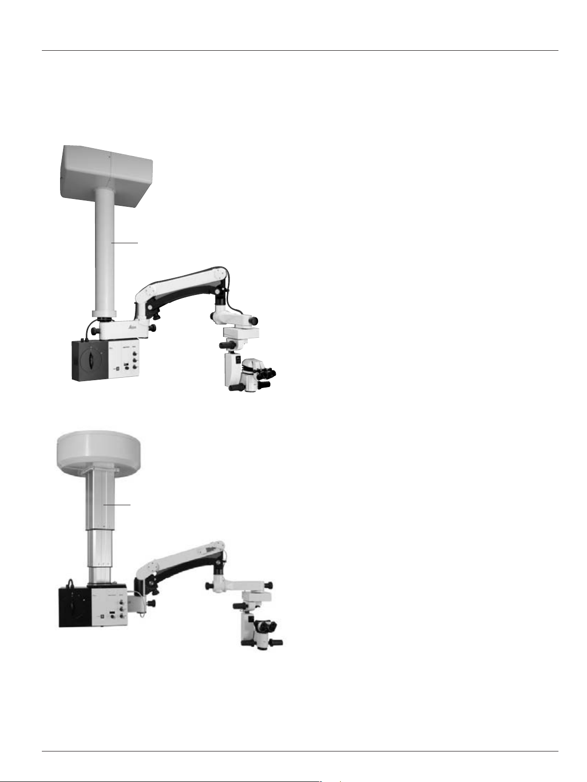
Ceiling mounts
1 Mini Mount ceiling mount
1
2 Leica Telescope Mount
2
6 Leica M501 / Ref. 10 711 785 / Version D
Controls
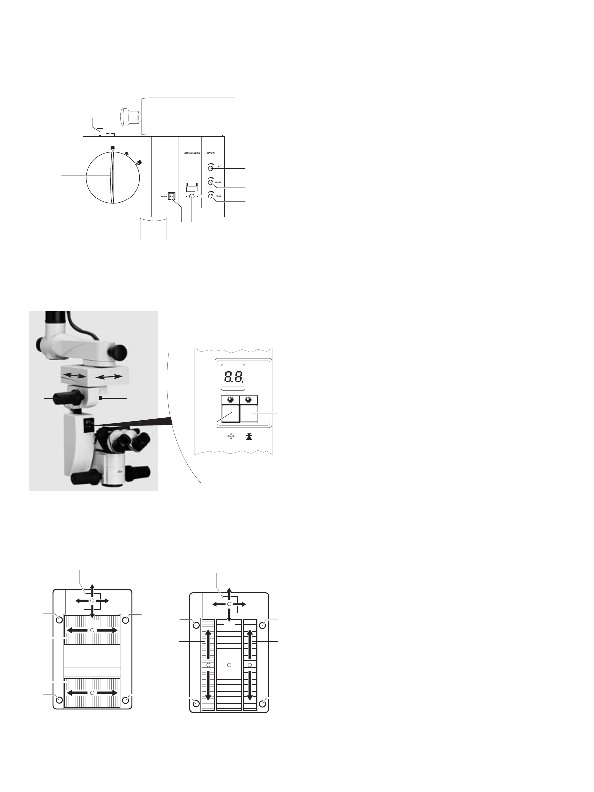
Control unit/lamp housing
6
2
3
4
51
7
2
1
•
XY-Reverse
Tilt head
3 Tilt head fine adjustment
4 Brake knob for rough adjusting
the tilt
Focusing unit
1 XY-unit reset button
2 Focus reset button
5
4
+
-
7
1
2
3
6
5
4
+
-
3
7
1
2
6
Footswitch
Cross pedal variant Vertical pedal variant
1 Main switch
2 Regulating knob for adjusting the travel speed of the
XY-coupling
3 Regulating knob for adjusting the travel speed of the
focus
4 Regulating knob for adjusting the travel speed of the
zoom
5 Regulating knob for adjusting the brightness of the
illumination
6 Rotary knob for changing filters
7 Turn grip for the quick-change lamp mount
1 XY adjustment
2 Focus up and down
3 Zoom up and down
4 Greater illumination
5 Less illumination
6 XY-Reverse
7 Microscope illumination on/off
Tilt head/focusing unit
3
4
7Leica M501 / Ref. 10 711 785 / Version D
Controls
ZF
A
2
3
6
45
1
7
ML
XY
SL
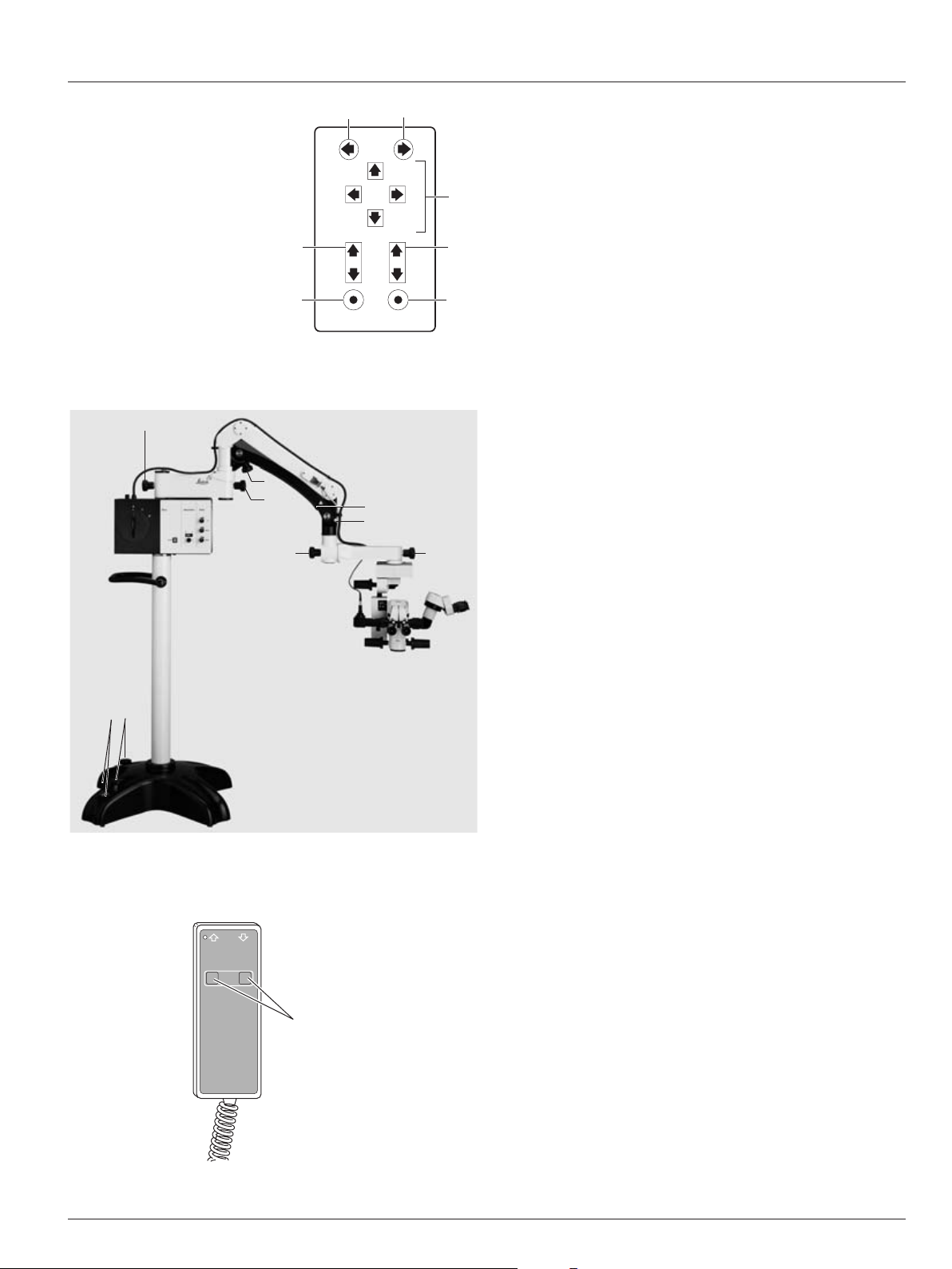
Handswitch
1 XY adjustment
2 Focus up and down
3 Zoom up and down
4 Greater illumination
5 Less illumination
6 XY-Reverse
7 Microscope illumination on/off
Stand
1 Footbrakes
2 Footbrake release lever
3 Articulation brakes
4 Balance turn knob
5 Safety hook
6 Retaining pin
3
33
3
4
1
2
5
6
Remote control for Leica Telescope Mount
1
1 Buttons for up/down movement
8 Leica M501 / Ref. 10 711 785 / Version D
Controls
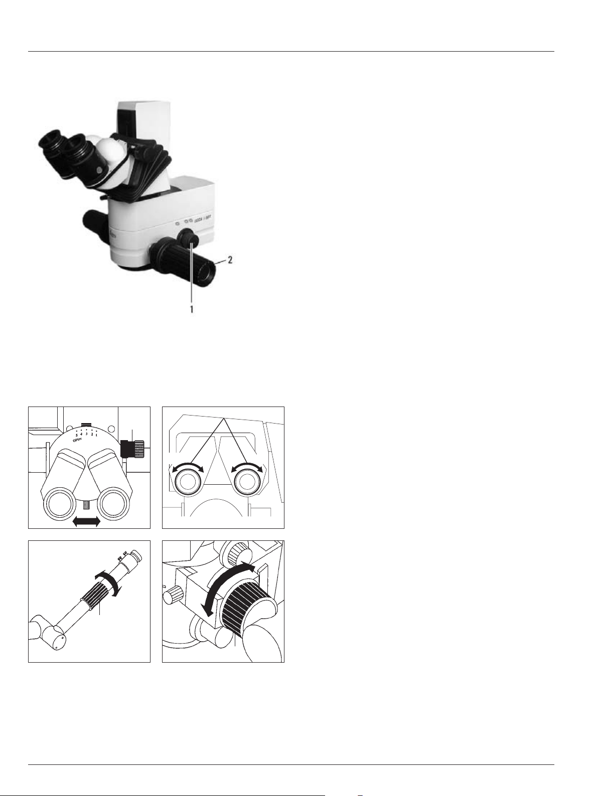
Optics carrier
1 Turn knob for fading ambient lighting
2 Handles
+5 -5 +5 -5
Binocular tube, eyepiece, tubes for second observer
1 Drive knob for adjusting the interpupillary distance
2 Diopter adjustment
3 Knurled ring for image correction
1
3
3
2
9Leica M501 / Ref. 10 711 785 / Version D
Preparation for Operation
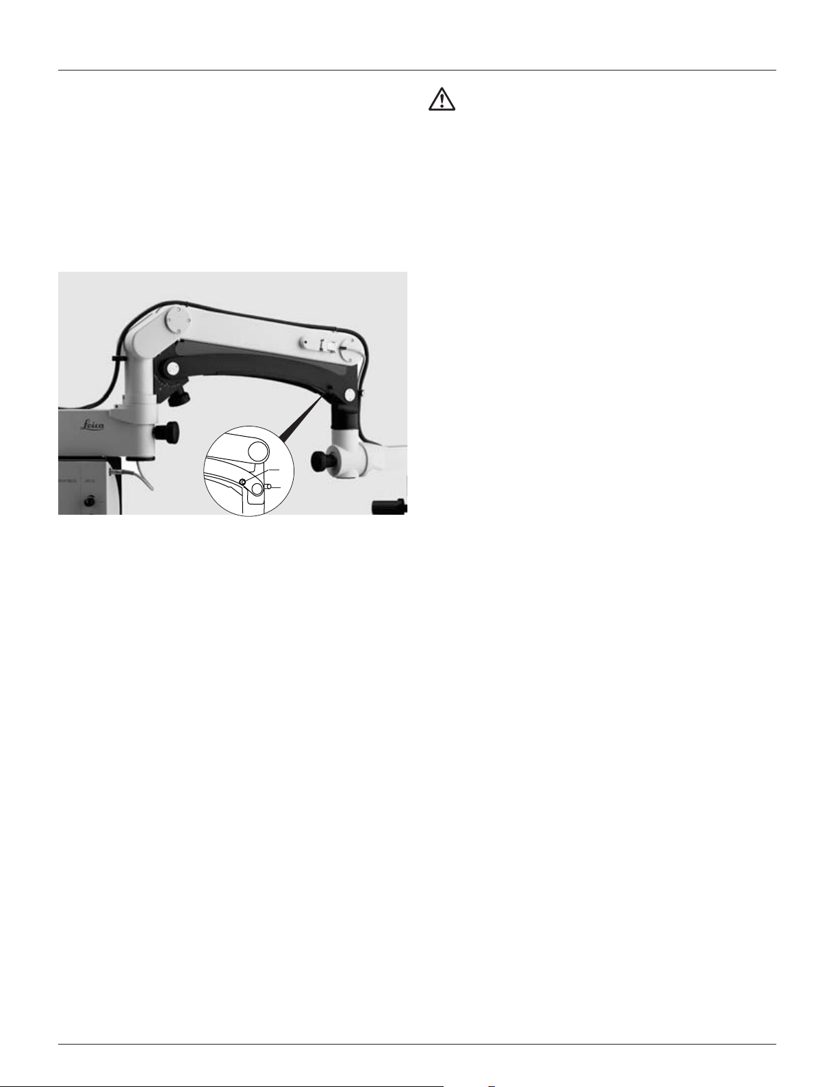
Lock the swing arm.
➩ Position the swing arm approximately horizontally.
➩ Pull out the retaining pin (3).
➩ Move the swing arm slightly up and down until the safety
hook (2) engages.
The swing arm is now locked.
Clean the optical accessories
➩ Inspect the eyepieces, objectives and any present photo and
TV-adapters for cleanliness.
➩ Remove dust and dirt.
Fitting accessories
➩ Equip the microscope ready for use with all necessary
accessories.
Balance the swing arm
➩ Hold the microscope firmly.
➩ Move the swing arm slightly up and down, at the same time
pushing the counterlever of the safety hook (2) upwards,
until the retaining pin clicks into position.
➩ See whether or not the microscope drifts.
Microscope drifts downwards:
➩ Turn rotary knob (4) clockwise.
Microscope drifts upwards:
➩ Turn rotary knob (4) counter-clockwise.
Warning 1
Risk of injury from the surgical microscope swinging
down!
➩Never rebalance or re-equip with the instrument over
the field of operation.
➩After re-equipping, always rebalance the swinging
arm.
Retrofit the surgical microscope and
balance the swinging arm
2
3
10 Leica M501 / Ref. 10 711 785 / Version D
Preparation for Operation
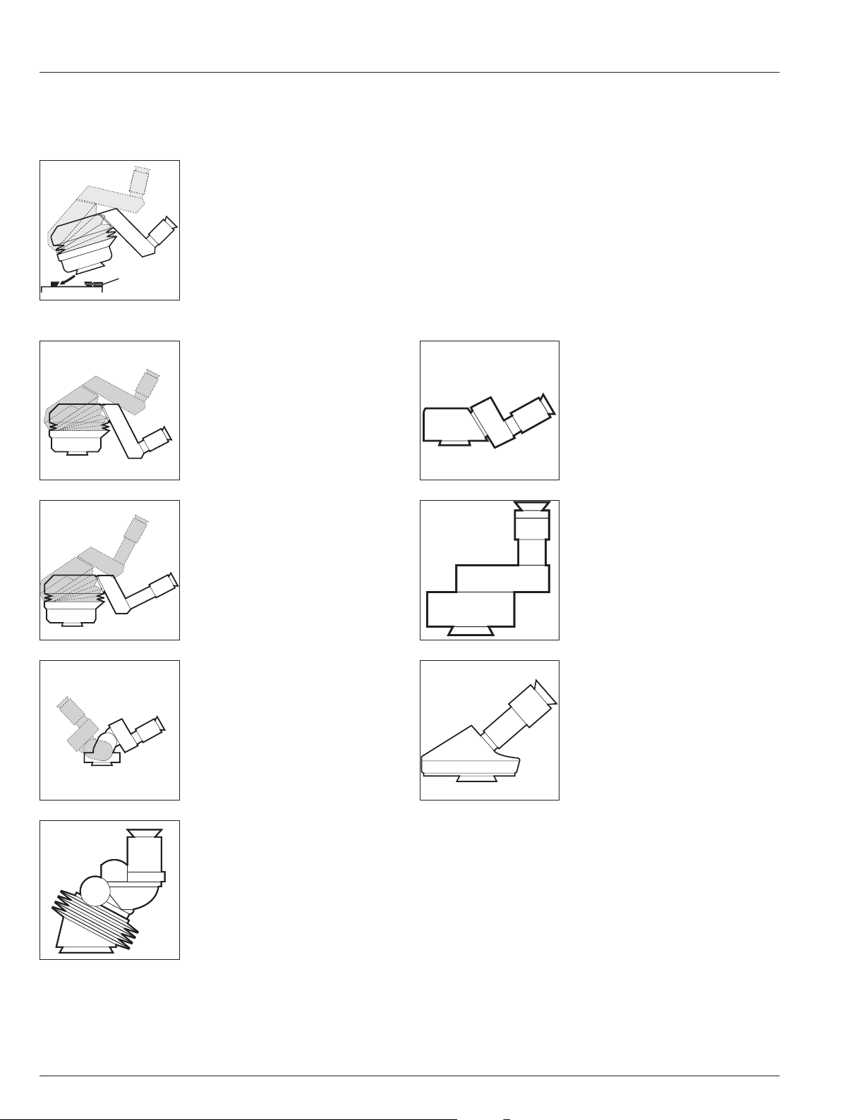
Attach the binocular tube, eyepiece and
objective
Binocular tube 10° – 50°, ultra low
Binocular tube 10° – 50°, low
Binocular tube with variable 180°
Binocular tube var. 30° – 150°
Attach the binocular tube
➩ Unscrew the clamping
screw (1).
➩ Push the binocular tube into
the dovetail ring.
➩ Tighten the clamping screw.
A range of options enables the Surgical Microscope to be
matched to the requirements of the task in hand.
Inclined binocular tube
Straight binocular tube
Inclined binocular tube 45°
Optional for use on the assistant’s
attachment
(no standard configuration)
1
11Leica M501 / Ref. 10 711 785 / Version D
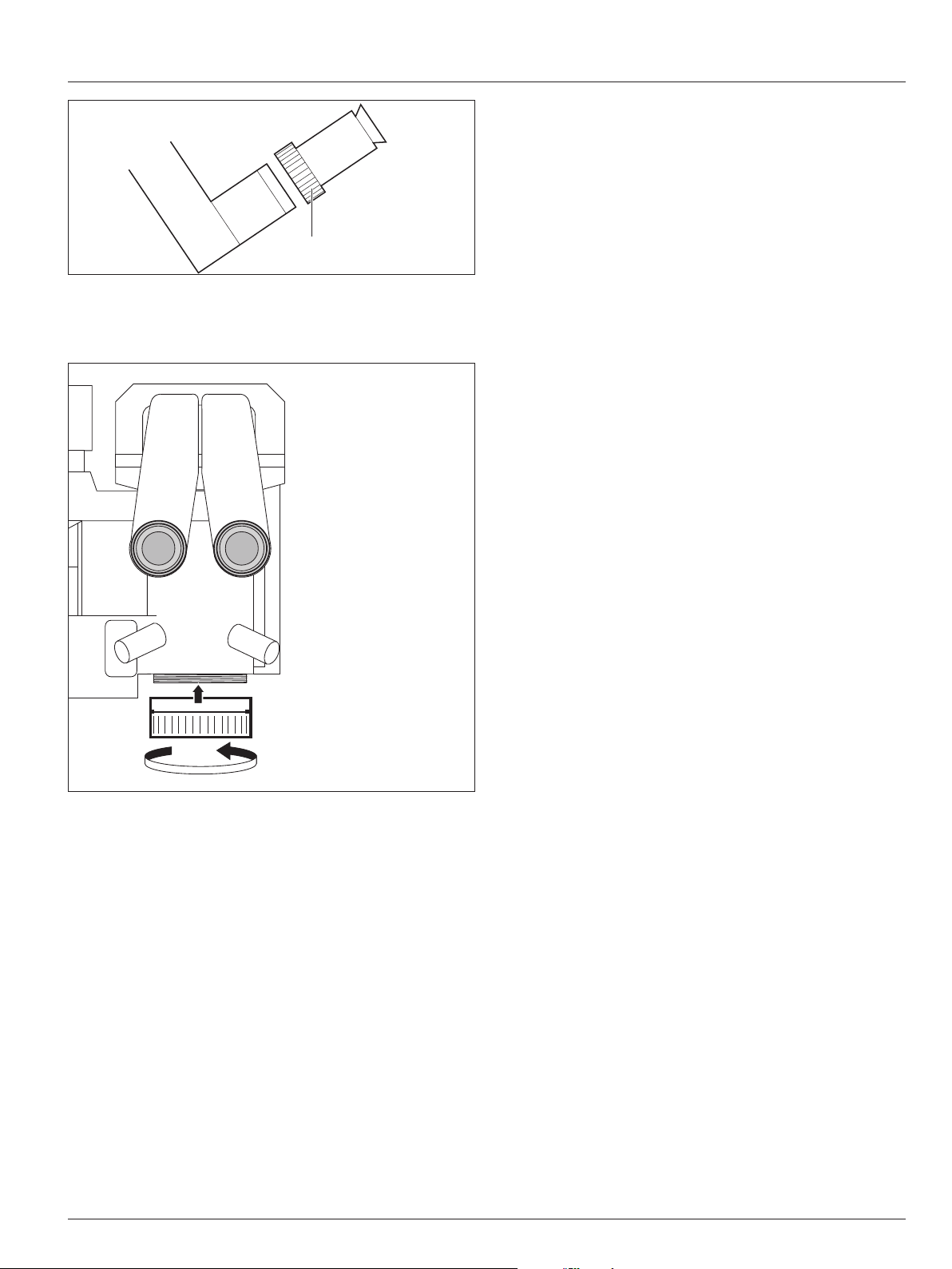
Preparation for Operation
1
Fitting the eyepiece
➩ Set the eyepiece in place.
➩ Tighten the rotary ring (1).
Eyepieces
Eyepiece 10x/21B, adjustable
Eyepiece 12.5x/17B, adjustable
Fitting objectives
Objectives are screwed in on the microscope with right-hand
threading.
Objectives
Objective WD = 175mm APO
Objective f = 175mm
Objective f = 200mm
Objective f = 225mm
Objective f = 250mm
Objective f = 275mm
Objective f = 300mm
12 Leica M501 / Ref. 10 711 785 / Version D12
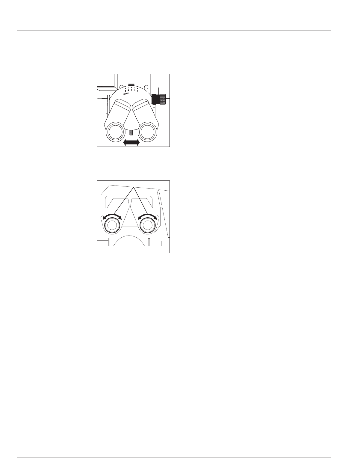
Preparation for Operation
The distance between both pupils and the desired contact with
the eyepieces are adjusted individually.
You can prepare the surgical microscope before the operation
using the data from a user table.
Regulate the interpupillary distance
➩ Turn the eyelenses on the eyepieces to "0" or set the dioptric
settings, if known.
➩ Set the magnification changer to step 10.
➩ Look through the eyepieces and adjust the tubes by hand
(for binocular tubes without drive knobs) or using the drive
knob (1) until you see a concentrically circular image field.
Set the interpupillary distance and
eyepoint
Adjust for parfocality
1
Adjusting the dioptric settings
Adjust the dioptric settings accurately for each eye separately;
only this method will ensure that the image will stay in
focus throughout the entire zoom range (parfocal).
1. Prepare the microscope
➩ Switch on the microscope at the control unit and place a flat
test object such as a piece of paper beneath the objective.
➩ Engage the highest brightness.
➩ Engage the lowest magnification.
➩ Displace the microscope so that the test object is visible in
the center of the field of view.
2. Focus on the test object
➩ Engage the highest magnification.
➩ Bring the test object into focus.
➩ Engage the lowest magnification.
3. Adjust the dioptric settings
➩ Adjust the dioptric settings for each eye in turn (2), so that
the image is seen in sharp focus.
➩ Engage the highest magnification.
➩ Refocus using motor-driven focusing.
➩ Engage the lowest magnification.
➩ Inspect the dioptric settings, readjusting them if necessary
so that both images are sharp.
4. Inspect the parfocality
➩ Zoom through the whole range, observing the test object.
The image sharpness must remain constant at all magnifica-
tions. If it does not, then repeat points 2 to 4 of this proce-
dure.
+5 -5 +5 -5
2
 Loading...